EP0930607A2 - Ultraschallfühler - Google Patents
Ultraschallfühler Download PDFInfo
- Publication number
- EP0930607A2 EP0930607A2 EP99100439A EP99100439A EP0930607A2 EP 0930607 A2 EP0930607 A2 EP 0930607A2 EP 99100439 A EP99100439 A EP 99100439A EP 99100439 A EP99100439 A EP 99100439A EP 0930607 A2 EP0930607 A2 EP 0930607A2
- Authority
- EP
- European Patent Office
- Prior art keywords
- input
- ultrasonic sensor
- output terminals
- cylindrical case
- cylinder part
- Prior art date
- Legal status (The legal status is an assumption and is not a legal conclusion. Google has not performed a legal analysis and makes no representation as to the accuracy of the status listed.)
- Granted
Links
- 239000000463 material Substances 0.000 claims abstract description 44
- 239000000853 adhesive Substances 0.000 claims abstract description 31
- 230000001070 adhesive effect Effects 0.000 claims abstract description 31
- 229920005989 resin Polymers 0.000 claims description 18
- 239000011347 resin Substances 0.000 claims description 18
- 238000005187 foaming Methods 0.000 claims description 16
- 238000009413 insulation Methods 0.000 claims description 5
- 239000012774 insulation material Substances 0.000 claims description 5
- 229910000906 Bronze Inorganic materials 0.000 claims description 2
- 229910001030 Iron–nickel alloy Inorganic materials 0.000 claims description 2
- OAICVXFJPJFONN-UHFFFAOYSA-N Phosphorus Chemical compound [P] OAICVXFJPJFONN-UHFFFAOYSA-N 0.000 claims description 2
- 239000010974 bronze Substances 0.000 claims description 2
- KUNSUQLRTQLHQQ-UHFFFAOYSA-N copper tin Chemical compound [Cu].[Sn] KUNSUQLRTQLHQQ-UHFFFAOYSA-N 0.000 claims description 2
- MOFOBJHOKRNACT-UHFFFAOYSA-N nickel silver Chemical compound [Ni].[Ag] MOFOBJHOKRNACT-UHFFFAOYSA-N 0.000 claims description 2
- 239000010956 nickel silver Substances 0.000 claims description 2
- 230000035945 sensitivity Effects 0.000 description 19
- 238000010276 construction Methods 0.000 description 12
- 238000000034 method Methods 0.000 description 10
- 239000004020 conductor Substances 0.000 description 9
- 229910000679 solder Inorganic materials 0.000 description 6
- RYGMFSIKBFXOCR-UHFFFAOYSA-N Copper Chemical compound [Cu] RYGMFSIKBFXOCR-UHFFFAOYSA-N 0.000 description 5
- 230000006866 deterioration Effects 0.000 description 5
- 230000007613 environmental effect Effects 0.000 description 5
- 230000005764 inhibitory process Effects 0.000 description 5
- 229910052782 aluminium Inorganic materials 0.000 description 4
- XAGFODPZIPBFFR-UHFFFAOYSA-N aluminium Chemical compound [Al] XAGFODPZIPBFFR-UHFFFAOYSA-N 0.000 description 4
- PXHVJJICTQNCMI-UHFFFAOYSA-N nickel Substances [Ni] PXHVJJICTQNCMI-UHFFFAOYSA-N 0.000 description 4
- 238000005452 bending Methods 0.000 description 3
- 238000003754 machining Methods 0.000 description 3
- 238000004519 manufacturing process Methods 0.000 description 3
- 229910052751 metal Inorganic materials 0.000 description 3
- 239000002184 metal Substances 0.000 description 3
- 229910052759 nickel Inorganic materials 0.000 description 3
- 229920002050 silicone resin Polymers 0.000 description 3
- 239000002689 soil Substances 0.000 description 3
- 238000005476 soldering Methods 0.000 description 3
- 230000036962 time dependent Effects 0.000 description 3
- 229920000106 Liquid crystal polymer Polymers 0.000 description 2
- 239000004977 Liquid-crystal polymers (LCPs) Substances 0.000 description 2
- 239000004696 Poly ether ether ketone Substances 0.000 description 2
- 239000004695 Polyether sulfone Substances 0.000 description 2
- 239000004734 Polyphenylene sulfide Substances 0.000 description 2
- 230000002411 adverse Effects 0.000 description 2
- 229910052802 copper Inorganic materials 0.000 description 2
- 239000010949 copper Substances 0.000 description 2
- 230000000694 effects Effects 0.000 description 2
- 230000002401 inhibitory effect Effects 0.000 description 2
- 238000001746 injection moulding Methods 0.000 description 2
- WABPQHHGFIMREM-UHFFFAOYSA-N lead(0) Chemical compound [Pb] WABPQHHGFIMREM-UHFFFAOYSA-N 0.000 description 2
- 229920006393 polyether sulfone Polymers 0.000 description 2
- 229920002530 polyetherether ketone Polymers 0.000 description 2
- 229920000069 polyphenylene sulfide Polymers 0.000 description 2
- 238000004080 punching Methods 0.000 description 2
- 229910000640 Fe alloy Inorganic materials 0.000 description 1
- 230000000994 depressogenic effect Effects 0.000 description 1
- 229920006351 engineering plastic Polymers 0.000 description 1
- 230000002349 favourable effect Effects 0.000 description 1
- 239000007788 liquid Substances 0.000 description 1
- 238000005259 measurement Methods 0.000 description 1
- 238000003825 pressing Methods 0.000 description 1
- 238000003466 welding Methods 0.000 description 1
Images


Classifications
-
- G—PHYSICS
- G01—MEASURING; TESTING
- G01H—MEASUREMENT OF MECHANICAL VIBRATIONS OR ULTRASONIC, SONIC OR INFRASONIC WAVES
- G01H11/00—Measuring mechanical vibrations or ultrasonic, sonic or infrasonic waves by detecting changes in electric or magnetic properties
- G01H11/06—Measuring mechanical vibrations or ultrasonic, sonic or infrasonic waves by detecting changes in electric or magnetic properties by electric means
- G01H11/08—Measuring mechanical vibrations or ultrasonic, sonic or infrasonic waves by detecting changes in electric or magnetic properties by electric means using piezoelectric devices
-
- G—PHYSICS
- G10—MUSICAL INSTRUMENTS; ACOUSTICS
- G10K—SOUND-PRODUCING DEVICES; METHODS OR DEVICES FOR PROTECTING AGAINST, OR FOR DAMPING, NOISE OR OTHER ACOUSTIC WAVES IN GENERAL; ACOUSTICS NOT OTHERWISE PROVIDED FOR
- G10K9/00—Devices in which sound is produced by vibrating a diaphragm or analogous element, e.g. fog horns, vehicle hooters or buzzers
- G10K9/12—Devices in which sound is produced by vibrating a diaphragm or analogous element, e.g. fog horns, vehicle hooters or buzzers electrically operated
- G10K9/122—Devices in which sound is produced by vibrating a diaphragm or analogous element, e.g. fog horns, vehicle hooters or buzzers electrically operated using piezoelectric driving means
Definitions
- the present invention relates to an ultrasonic sensor, especially to a waterproof ultrasonic sensor used for a back sonar and corner sonar of automobiles.
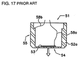
- the ultrasonic sensor 51 has a construction in which a piezoelectric vibration element 53, on both main faces of which element electrodes (not shown in the drawing) are formed, is adhered at the inside of a vibration part (bottom face) 54 of a floored cylindrical case 52a that is integrally formed of a metal, such as aluminum, by a cylinder part 55 and the vibration part 54. Electrical connection from the element electrode formed on the piezoelectric vibration element 53 to the outside of the case 52a is achieved via input-output terminals 58a and 58b.
- the input-output terminal 58a is connected to the element electrode formed on the main face at the side (top face side) not making contact with the vibration part 54 of the piezoelectric vibration element 53 by, for example, soldering.
- the input-output terminal 58b is connected to a prescribed position of the metal case 52a which is in electric connection with the element electrode formed on the main face at the side (bottom face side) making contact with the vibration part 54 of the piezoelectric vibration element 53 by, for example, soldering.
- the construction as described above allows electrical connection from the element electrodes to be formed with the input-output terminals 58a and 58b.
- a soil and fine copper wire is used for the wiring material of the input-output terminals 58a and 58b. If a highly rigid wiring material, such as a lead frame comprising, for example, an iron-nickel alloy is used for the input-output terminal, then the input-output terminal is inserted from the opening of the cylindrical case 52a toward the vibration part 54 to achieve electrical connection by pressing the tip of the input-output terminal into contact with the piezoelectric vibration element 53. However, if the piezoelectric vibration element is pressed down with the input-output terminal, it results in inhibition (restriction) of naturally required vibration of the element 53.
- a highly rigid wiring material such as a lead frame comprising, for example, an iron-nickel alloy
- a vibration suppressing material such as a silicone resin (not shown) is usually inserted into the empty space inside of the cylindrical case of the foregoing ultrasonic sensor 51.
- the ultrasonic sensor with the construction as described above operates as follows. Firstly, a driving voltage is applied to the input-output terminals 58a and 58b to allow the piezoelectric vibration element 53 to vibrate. This vibration forces the vibration part 54 of the floored cylindrical case 52 to vibrate, emitting an ultrasonic wave toward the direction indicated by the arrow in FIG. 17. After a prescribed time interval, the ultrasonic wave reflected back from the sensed object arrives at the piezoelectric vibration element 53 via the vibration part 54 and is converted into a reflection signal, followed by output of output signals from the input-output terminals 58a and 58b. Then, the time interval from application of the driving voltage through the output of the reflection signals is detected, thereby measuring the distance between the sensor and the sensed object.
- the floored cylindrical case 52a is integrally constructed with the cylinder part 55 and the vibration part 54. While such an integrated case may be usually produced by machining, the inner diameter of the cylindrical case and the thickness of the vibration part are liable to variation in dimensions. Variation in dimensions of the inner diameter and thickness so greatly affect such characteristics of the ultrasonic sensor, such as resonance frequency, sensitivity and reverberation, that it becomes difficult to effectively produce the ultrasonic sensors with uniform characteristics, resulting in poor productivity. The machining process also brings about increases in cost of the ultrasonic sensor because of the expensive material employed.
- a soil and fine copper wire is used for the input-output terminals 58a and 58b in the ultrasonic sensor with the foregoing construction from the view point of not adversely affecting the required vibration and reverberation characteristics of the vibration element.
- handling of the fine and soil input-output terminals is difficult.
- the fine input-output terminals may be broken due to the effect of vibration of the piezoelectric vibration element, thereby adversely affecting the reliability of the electrical connection.
- the object of the present invention is to solve the foregoing technical problems by providing a floored cylindrical case with easy machinability, uniform characteristics, cheap production cost, ready connectability of the input-output terminals to the piezoelectric vibration element and easy positioning of the contact site.
- An ultrasonic sensor comprises a floored cylindrical case, a piezoelectric vibration element disposed on the inner bottom floor of the floored cylindrical case and input-output terminals electrically connected to the piezoelectric vibration element and adapted to be electrically connected to the outside of the floored cylindrical case.
- the floored cylindrical case has a separately prepared cylinder part and a separately prepared vibration part, the cylinder part and the vibration part being adhered to each other with an adhesive material having an elastic modulus in the range from 100 through 20,000 kgf/mm 2 at a temperature range from 25 through 125°C.
- Constructing the floored cylindrical case by integrating the separately formed cylinder part and vibration part allows the inner diameter of the floored cylindrical case and thickness of the vibration part to be produced with higher accuracy than producing a monolithic floored cylindrical case composed of a cylinder part and vibration part by machining.
- mass-production of the cylinder part with a uniform inner diameter is made easy by using a resin mold while a vibration part with a uniform thickness can be formed by punching of a thin metal plate.
- the floored cylindrical case is constructed by integrating the cylindrical part and vibration part.
- Selection of the adhesive material is important because the sensor according to the present invention is expected to be used under severe conditions as a component mounted on automobiles. It is essential for this purpose that the ultrasonic sensor substantially maintains its sensitivity and reverberation characteristics and not experience time-dependent deterioration even under severe conditions. Environmental reliability of the adhered site between the cylinder part and vibration part is one of the crucial factors for satisfying the conditions described above.
- the inventors of the present invention have confirmed, as will be shown in the embodiments to be described hereinafter, that the desired sensitivity characteristic and reverberation characteristic can be satisfied under expected environmental conditions by adhering the cylinder part with the vibration part by using an adhesive material having an elastic modulus of 100 to 20,000 kgf/mm 2 in the temperature range from 25 through 125°C.
- An ultrasonic sensor comprises a floored cylindrical case, a piezoelectric vibration element disposed on the inner bottom floor of the floored cylindrical case and input-output terminals electrically connected to the piezoelectric vibration element and adapted to be electrically connected to the outside of the floored cylindrical case.
- the floored cylindrical case has a separately prepared cylinder part composed of an insulation member and a separately prepared vibration part composed of an electrically conductive member, at least one of the input-output terminals being buried into the cylinder part.
- Burying the input-output terminals into the cylinder part enables the input-output terminals to be adequately fixed and supported with the cylinder part, thereby making it possible to more readily position the contact site for connecting the input-output terminals to the piezoelectric vibration element as compared with conventional ultrasonic sensors. It is also made possible to effectively produce the ultrasonic sensor with little variation in the location of the contact sites.
- the wiring material composed of a highly rigid conductive material as the input-output terminal because the input-output terminals are fixed and supported with the cylinder part.
- the tip of the input-output terminals can be electrically connected without being directly pressed into contact with the piezoelectric vibration element even when a highly rigid conductive material is used since the conductive material is fixed and supported with the cylinder part.
- Electric continuity can be achieved without inhibiting (restricting) vibration of the piezoelectric vibration element and the vibration part by allowing the terminals to make contact with the piezoelectric vibration element and the vibration part via a conductive adhesive or solder by taking advantage of a spring action of the part of the input-output terminal projecting out of the portion buried into the cylinder part (i.e., the tip of the buried input-output terminal).
- At least one of the input-output terminals be electrically connected to the piezoelectric vibration element at the side thereof not making contact with the vibration part.
- a conductive member is used for the vibration part in the ultrasonic sensor
- an insulation member may be used for the vibration part.
- a certain means for example connecting the terminals via a conductive adhesive or solder after forming a depression on the vibration part, should be devised in this case, advantages such as separately forming the cylinder part and vibration part and using a highly rigid electrically conductive material can still be attained.
- the independently formed cylinder part and vibration part are preferably adhered with each other using an adhesive material having an elastic modulus of 100 to 20,000 kgf/cm 2 at a temperature range from 25 through 125°C.
- the elastic modulus of the cylinder part is preferably in the range of 100 to 20,000 kgf/cm 2 at a temperature range from 25 through 125°C.
- the elastic modulus of the vibration part is in the range of 100 to 20,000 kgf/cm 2 at a temperature range from 25 through 125°C.
- materials, having the elastic modulus as prescribed above and suitable for use in the ultrasonic sensor according to the present invention, for forming the cylinder part include insulation materials such as polyphenylene sulfide, polyetherether ketone, polyether sulfone and liquid crystal polymers, while examples of the material for forming the vibration part are conductive materials such as aluminum.
- the tip of the buried input-output terminals inside of the floored cylindrical case may have at least one or more bent portions. Forming at least one bent portion on the input-output terminal enables the tip of the buried input-output terminal to be longer, allowing improved spring action of the tip of the buried input-output terminal to reduce the inhibition (restriction) force against vibration.
- the buried tip of the input-output terminals inside of the floored cylindrical case is preferably formed to have a length/thickness ratio of 2 or more and a length/width ratio of 2 or more. Making the tip of the buried input-output terminal to have such dimensional ratio enables the spring action of the tip of the input-output terminal to be improved to reduce the inhibition (restriction) force against vibration.
- the tip of the buried input-output terminals inside of the floored cylindrical case may be formed into a tapered shape toward its tip direction or into a partially depressed shape. This enables the spring action of the tip of the buried input-output terminal to be improved to reduce the inhibition (restriction) force against vibration.
- the inside of the floored cylindrical case may be at least partially filled with a foaming resin.
- the foaming resin suppresses excess vibration of the floored cylindrical case as well as absorbs excess ultrasonic waves generated in the case, thereby allowing improved reverberation characteristic of the ultrasonic sensor.
- an ultrasonic sensor 1 comprises a floored cylindrical case 2 constructed of a separately formed insulative cylinder part 3 and a separately formed conductive vibration part 4 adhered to each other with an adhesive material 60.
- part 3 is referred to as the "cylinder part” and part 4 is referred to as the "vibration part”
- Two input-output terminals 6 and 7 composed of a highly rigid conductive member such as 42-nickel (an alloy of iron with 42% of nickel) are buried into the cylinder part 3.
- One end of the input-output terminal 6 is electrically connected to the element electrode formed on the top face of the piezoelectric vibration element 5 via a conductive adhesive 8.
- the tip portion of the buried input-output terminal makes a light touch to the piezoelectric vibration element 5 by taking advantage of spring action of the buried tip portion 9 so as not to inhibit (restrict) the desired vibration of the piezoelectric vibration element 5 and vibration part 4.
- the tip 9 of the buried input-output terminal may be subjected to bending with an adequate angle so that the tip displays a proper spring action.
- the other end of the input-output terminal 6 extends to outside of the case 2 for electrical connection to auxiliary circuits.
- One end of the input-output terminal 7 is pressed and makes contact with the vibration part 4, as shown by the reference numeral 10 in FIG. 1, forming an electrical connection with the element electrode formed on the bottom face of the piezoelectric vibration element 5 via the vibration part 4.
- the other end of the input-output terminal 7 also extends to outside of the case 2.
- a vibration suppressing material such as a silicone resin may be sometimes inserted into the empty space inside of the floored cylindrical case 2 of the foregoing ultrasonic sensor 1 in order to improve the reverberation characteristic.
- a material having an elastic modulus of 100 to 20,000 kgf/cm 2 at a temperature range from 25 through 125°C is desirable as the insulation member for use in the cylinder part 3.
- Examples of such a material are engineering plastics with good heat resistance and durability such as polyphenylene sulfide, polyetherether ketone, polyether sulfone and liquid crystal polymers.
- a material having an elastic modulus of 100 to 20,000 kgf/cm 2 at a temperature range from 25 through 125°C is also desirable as the conductive member for use in the vibration part 4.
- Examples of such a material include aluminum that is light-weight and easily machinable.
- the ultrasonic sensor according to the present invention is expected to be used under a severe environment as a part mounted on an automobile. For that purpose, the sensor is required to substantially maintain its characteristics such as sensitivity and reverberation and not experience time-dependent deterioration even under severe environmental conditions. With respect to this point, the inventors of the present invention have confirmed that the desired sensitivity characteristic and reverberation characteristic can be satisfied under the expected environmental conditions by using the materials having elastic moduli within the foregoing range.
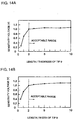
- FIG. 3A, 3B, 4A and 4B are the graphs indicating the relation of the elastic moduli of the materials to be used for the vibration part against the sensitivity and reverberation of the ultrasonic sensor. It is evident from the respective graphs that the reverberation characteristic steeply turns to favorable values at elastic moduli of 100 kgf/mm 2 or more, and that the reverberation characteristic remains very good up to elastic moduli of 20,000 kgf/mm 2 or below.
- the ultrasonic sensor in which the floored cylindrical case is constructed using the material having elastic moduli within the range as described above for the respective cylinder part and vibration part, is used for a prescribed time period under expected environmental conditions, it was confirmed that characteristic changes well remained within the allowable range.
- the ultrasonic sensor 1 with a construction as described above is produced as follows.
- a cylinder part 3 in which the input-output terminals 6 and 7 are buried is formed by injection molding.
- the vibration part is also separately prepared by punching an aluminum plate and the piezoelectric vibration element 5 is adhered and fixed on the vibration part 4 with a solder or a conductive adhesive while the cylinder part 3 and vibration part 4 remain still separated with each other.
- the cylinder part 3 and vibration part 4 are integrated by adhering one to the other with the adhesive material 60, thereby constructing the floored cylindrical case 2.
- the input-output terminals 6 and 7 are put into electrical connection using a solder or conductive adhesive when necessary, followed by inserting the vibration suppressing material into the floored cylindrical case 2, if necessary. Bending of the input-output terminals may be applied either before or after the injection molding of the cylinder part 3, or it may be carried out after integrating the cylinder part 3 and vibration part 4.
- the operation of the ultrasonic sensor 1 is as follows. Firstly, a driving voltage is impressed on the input-output terminals 6 and 7 to allow the piezoelectric vibration element 5 to vibrate.
- the vibration part 4 is vibrated in harmony with vibration of the piezoelectric vibration element 5, emitting an ultrasonic wave toward the arrow direction shown in FIG. 1.
- the ultrasonic wave reflected back from the sensed object reaches to the piezoelectric vibration element 5 via the vibration part 4 and is converted into reflection signals, which are transmitted from the input-output terminals 6 and 7.
- the time interval from impression of the driving voltage through output of the reflection signals is then detected to measure the distance from the sensor to the sensed object from the results of measurement.
- the ultrasonic sensor with the construction as hitherto described makes it possible to produce cylinder parts and vibration parts having high dimensional accuracy cheap with good mass-productivity by assembling separately formed cylinder parts and vibration parts into floored cylindrical cases. Burying the input-output terminals into the cylinder part allows the input-output terminals to be fixed to the cylinder part, thereby making the positioning work of the contact site easy in connecting the input-output terminals to the piezoelectric vibration element, along with making it possible to effectively produce ultrasonic sensors having uniform characteristics. Highly rigid conductive members can be used for the input-output terminals since the input-output terminals are fixed at the cylinder part.
- the element electrodes are formed on both main faces of the piezoelectric vibration element 5 in the present embodiment, for example, it is not always necessary that the element electrodes are formed on the main face at the side making a contact with the vibration part 4, because it is also possible to allow the vibration part 4, comprising a conductive member, to function as the element electrode.
- 42-nickel was used for the lead wire material of the input-output terminals, use of nickel silver or phosphor bronze as similar highly rigid lead wire materials are also possible.
- Use of conventional fine copper wire, as well as wire materials with high rigidity is also possible. Positioning is made easier than usual in connecting a fine wire to the piezoelectric vibration element 5 since the fine wire is buried into the cylinder part 3 to substantially fix and support it.
- both of the two input-output terminals are buried into the cylinder part 3 in the present embodiment, only one can be buried.
- the methods for connecting the input-output terminals 6 and 7 are not limited to that shown in the embodiment of Fig. 1.
- the input-output terminal 7, like the terminal 6, may be passed through the side wall portion of the cylinder part 3 to connect to the vibration part 4 using a conductive adhesive 8 as shown in FIG. 2.
- Many embodiments are also possible for the method for bending the input-output terminals.
- connection of the cylinder part 3 with the vibration part 4 connection between them may be carried out by soldering or welding instead of adhesion with adhesives.
- an ultrasonic sensor 11 is, like the ultrasonic sensor 1 according to the first embodiment, constructed of a floored cylindrical case 12 in which a separately formed cylinder part 13 and a separately formed vibration part 14 are integrated by adhering one to the other using an adhesive material 60.
- the present embodiment is characterized in that not only the cylinder part 13 but also the vibration part 14 is formed of an insulation material.
- the insulation materials for the cylinder part 13 and the vibration part 14 and the adhesive material 60 are the same as those explained in the first embodiment.
- a thin plate of piezoelectric vibration element 15 on both main faces of which element electrodes (not shown in the drawing) are formed, is disposed on the vibration part 14 corresponding to the inner bottom face of the floored cylindrical case 12.
- the vibration part 14 of the ultrasonic sensor 11 is formed of an insulation member. Accordingly, a conductive film 19 is formed on the surface at the inner side of the vibration part 14 for electrical connection between the input-output terminal 17 and the element electrode at the lower face side of the piezoelectric vibration element 15. More specifically, the tip of the input-output terminal 17 is electrically connected to the conductive film 19 with a conductive adhesive 18, thereby putting the tip of the input-output terminal 17 into electrical connection with the element electrode at the bottom face side of the piezoelectric vibration element 15 which is electrically connected to the conductive film 19. Explanation of the other constructions are omitted since they are not different from the ultrasonic sensor according to the first embodiment.
- the construction of the electrical connection between the input-output terminal 17 and piezoelectric vibration element 15 becomes somewhat complicated as compared with the piezoelectric sensor according to the first embodiment, it is made possible to cheaply produce the cylinder part 13 and vibration part 14 having a high dimensional accuracy with good mass-productivity.
- the input-output terminals 17 are fixed at the cylinder part 13 by burying the input-output terminals into the cylinder part 13, positioning of the connection site becomes easy, i.e., it is easy to put the input-output terminals into electrical connection with the piezoelectric vibration element 15. This allows an ultrasonic sensor with uniform characteristics to be effectively produced.
- the method for electrically connecting the element electrodes at the bottom face side of the piezoelectric vibration element 15 to the input-output terminals are not necessarily limited to the methods described above.
- the element electrode 20 may be put into electrical connection with the input-output terminal 17 after elongating the element electrode 20 up to the top face side via the side portion of the piezoelectric vibration element 15.
- the conductive adhesive 18 is placed in a depression 16 formed in the vibration part 14, followed by putting the element electrode (not shown in the drawing) at the bottom face side into electrical connection with the input-output terminal 17 via the adhesive 18.
- An ultrasonic sensor 31 comprises a floored cylindrical case 32 in which a separately formed cylinder part 33 and a separately formed vibration part 34 are integrated by adhering them together with an adhesive material 60 as shown in FIG. 9.
- the present embodiment is characterized in that both the cylinder part 33 and the vibration part 34 are formed of a conductive material.
- the conductive materials for the cylinder part 33 and vibration part 34 and the adhesive material are the same as those explained in the first embodiment.
- a thin plate of a piezoelectric vibration element 35 is disposed on the vibration part 34 corresponding to the inner bottom face of the floored cylindrical case 32.
- the cylinder part 33 is formed of a conductive member in the present embodiment, it is difficult to bury the input-output terminals 36 and 37 into the cylinder part as in the foregoing respective embodiments. Accordingly, the element electrode (not shown in the drawing) formed on both main faces of the piezoelectric vibration element 35 is put into electrical connection to outside of the case 32 using the same method as in the prior art. Actually, the input-output terminals 36 and 37 comprising a fine wire of copper are adhered with a solder or conductive adhesive to the element electrodes on the top face of the piezoelectric vibration element 35 or to the prescribed side of the floored cylindrical case put into electrical connection with the element electrodes on the bottom face of the piezoelectric vibration element. Description of the other constructions is omitted since they are the same as those of the ultrasonic sensor according to the first embodiment.
- the ultrasonic sensor having the construction as described above is forced to form electrical connection using a fine copper wiring as in the prior art due to the difficulty of burying the input-output terminals into the cylinder part because the cylinder part is formed of a conductive member. Thus, positioning of the contact site becomes difficult. However, because the cylinder part 33 and vibration part 34 are separately formed, high dimensional accuracy can be cheaply produced with good productivity.
- the ultrasonic sensor according to the present invention it is possible for the ultrasonic sensor according to the present invention to form the cylinder part 33 with a conductive material and the vibration part 34 with an insulation material.
- the method for forming electrical connection from the element electrode at the bottom side of the piezoelectric vibration element 35 becomes a little bit more complicated as compared with the case when a conductive material is used for the vibration part 34, the advantage of separately forming the cylinder part 33 and the vibration part still results.
- An ultrasonic sensor 41 according to a fourth embodiment of the present invention is characterized in that the tip 9 of the buried terminal corresponding to the tip in the ultrasonic sensor according to the first embodiment is endowed with a proper spring action by varying the shape of the tip 9 of the buried input-output terminal 6.
- the tip 9 of the buried terminal projecting out of the cylinder part 3 is formed to be a little longer in the ultrasonic sensor 41 as shown in FIG. 10. Since forming the tip 9 of the buried terminal longer allows its spring action to be enhanced, the inhibition (restriction) force of the input-output terminal 6 against vibration of the piezoelectric vibration element 5 and vibration part 4 is weakened, thereby improving the sensitivity characteristic of the ultrasonic sensor 41.
- the method for improving the spring action of the tip 9 of the buried terminal includes, in addition to the method as hitherto described, providing a bent portion at the tip 9 of the buried terminal as shown in FIG. 11 viewed from the axial direction of the floored cylindrical case 2. Providing a bent portion allows the tip 9 of the buried terminal to be longer, serving for improving its spring action.
- the shape of the bent portion includes, besides the L-shape as shown in FIG. 11, a variety of shapes such as a U-shape, meandering shape or spiral shape.
- a tapered portion 42 that makes the tip 9 of the buried terminal gradually slender may be provided, for example, as shown in FIG. 12.
- the shape of this tapered portion 42 is not limited to the shape shown in FIG. 12 but a step shape or a rounded shape may be used, or a slender depression may be partially provided at the tip 9 of the buried terminal.
- a good spring action of the tip 9 of the buried terminal can be obtained by adjusting the length/thickness ratio or the length/width ratio to 2 or more, respectively, after setting each dimension of the tip 9 of the buried terminal as shown in FIG. 13.
- FIGS. 14A and 14B are graphs showing the relation of the length/thickness ratio and length/width ratio to sensitivity of the ultrasonic sensor 41. It is evident from the graph that the sensitivity characteristic clearly shows good values up to the point where the length/thickness ratio and the length/width ratio is 2 or more, respectively. However, if it is desired to obtain an ultrasonic sensor with higher sensitivity, the length/thickness ratio and the length/width ratio may be 5 or more, respectively.
- each of the input-output terminals assumes a plate shape in the present embodiment, they are not necessarily limited to this shape but a cylindrical shape is also acceptable.
- the spring action of the tip 9 of the buried terminal can be also improved by assuming the dimensional ratio as described above. The methods for improving spring action do not have to be used alone but may be used in combination.
- An ultrasonic sensor 45 according to a fifth embodiment of the present invention is characterized in that, different from the ultrasonic sensor in the first embodiment, the floored cylindrical case 2 is filled with a foaming resin 46.
- the foaming resin 46 is filled in the entire inner space of the floored cylindrical case 2 as shown in FIG. 15. A force to press the cylinder part 3 from inside toward outside is applied due to expansion of the resin 46 when the interior of the floored cylindrical case 2 is filled with the foaming resin 46 so that excess vibration of the cylinder part 3 is suppressed.
- vibration of the piezoelectric vibration element 5 allows not only the vibration part 4 but also the cylinder part 3 to harmoniously vibrate
- vibration of the cylinder part 3 may be excessive and cause deterioration of the reverberation characteristic of the ultrasonic sensor.
- the reverberation characteristic can be improved by suppressing this excess vibration of the cylinder part 3 with expansion force of the foaming resin 46.
- the term "fill” as used herein refers not only to allowing the foaming resin liquid to flow into the floored cylindrical case 2 but also to inserting the solidified foaming resin into the case 2.
- the method for filling the foaming resin 46 is not limited to the embodiment shown in FIG. 15.
- the foaming resin 46 that has been solidified at outside of the case 2 is inserted and fixed in the floored cylindrical case 2 while an empty space remains above the piezoelectric vibration element 5. Disposing the foaming resin 46 with an empty space above the piezoelectric vibration element 5 prevents the foaming resin 46 from inhibiting (restricting) vibration of the piezoelectric vibration element 5 and, thus, enables a good sensitivity characteristic to be maintained.
- FIG. 16A for example, the foaming resin 46 that has been solidified at outside of the case 2 is inserted and fixed in the floored cylindrical case 2 while an empty space remains above the piezoelectric vibration element 5. Disposing the foaming resin 46 with an empty space above the piezoelectric vibration element 5 prevents the foaming resin 46 from inhibiting (restricting) vibration of the piezoelectric vibration element 5 and, thus, enables a good sensitivity characteristic to be maintained.
- the foaming resin 46 solidified at outside of the case 2 is inserted into and fixed in the case with an empty space above the piezoelectric vibration element 5, followed by filling a vibration suppressing material 47 such as a silicone resin on the foaming resin 46. Filling the vibration suppressing material 47 with high density on the foaming resin 46 enables vibration suppressing effect of the case 2 to be enhanced.
Landscapes
- Physics & Mathematics (AREA)
- Engineering & Computer Science (AREA)
- Acoustics & Sound (AREA)
- Multimedia (AREA)
- General Physics & Mathematics (AREA)
- Transducers For Ultrasonic Waves (AREA)
- Measurement Of Velocity Or Position Using Acoustic Or Ultrasonic Waves (AREA)
- Investigating Or Analyzing Materials By The Use Of Ultrasonic Waves (AREA)
- Piezo-Electric Transducers For Audible Bands (AREA)
Priority Applications (1)
| Application Number | Priority Date | Filing Date | Title |
|---|---|---|---|
| EP02020678A EP1265222A1 (de) | 1998-01-13 | 1999-01-11 | Gehäuse für einen Ultraschallwandler mit einzeln hergestelltem Zylinderteil und Schwingungsteil |
Applications Claiming Priority (4)
| Application Number | Priority Date | Filing Date | Title |
|---|---|---|---|
| JP488298 | 1998-01-13 | ||
| JP488298 | 1998-01-13 | ||
| JP23882398 | 1998-08-25 | ||
| JP23882398A JP3721798B2 (ja) | 1998-01-13 | 1998-08-25 | 超音波センサ |
Related Child Applications (2)
| Application Number | Title | Priority Date | Filing Date |
|---|---|---|---|
| EP02020678A Division EP1265222A1 (de) | 1998-01-13 | 1999-01-11 | Gehäuse für einen Ultraschallwandler mit einzeln hergestelltem Zylinderteil und Schwingungsteil |
| EP02020678A Division-Into EP1265222A1 (de) | 1998-01-13 | 1999-01-11 | Gehäuse für einen Ultraschallwandler mit einzeln hergestelltem Zylinderteil und Schwingungsteil |
Publications (3)
| Publication Number | Publication Date |
|---|---|
| EP0930607A2 true EP0930607A2 (de) | 1999-07-21 |
| EP0930607A3 EP0930607A3 (de) | 2001-11-21 |
| EP0930607B1 EP0930607B1 (de) | 2004-03-31 |
Family
ID=26338738
Family Applications (2)
| Application Number | Title | Priority Date | Filing Date |
|---|---|---|---|
| EP02020678A Withdrawn EP1265222A1 (de) | 1998-01-13 | 1999-01-11 | Gehäuse für einen Ultraschallwandler mit einzeln hergestelltem Zylinderteil und Schwingungsteil |
| EP99100439A Expired - Lifetime EP0930607B1 (de) | 1998-01-13 | 1999-01-11 | Ultraschallfühler, der ein zylindrisches Gehäuse enthält |
Family Applications Before (1)
| Application Number | Title | Priority Date | Filing Date |
|---|---|---|---|
| EP02020678A Withdrawn EP1265222A1 (de) | 1998-01-13 | 1999-01-11 | Gehäuse für einen Ultraschallwandler mit einzeln hergestelltem Zylinderteil und Schwingungsteil |
Country Status (6)
| Country | Link |
|---|---|
| US (1) | US6047603A (de) |
| EP (2) | EP1265222A1 (de) |
| JP (1) | JP3721798B2 (de) |
| KR (1) | KR100283846B1 (de) |
| DE (1) | DE69915902T2 (de) |
| TW (1) | TW539848B (de) |
Cited By (5)
| Publication number | Priority date | Publication date | Assignee | Title |
|---|---|---|---|---|
| GB2371624A (en) * | 2000-09-19 | 2002-07-31 | Sagem | Sensor with a three-dimensional interconnection circuit. |
| WO2009036826A1 (de) * | 2007-09-12 | 2009-03-26 | Valeo Schalter Und Sensoren Gmbh | Verfahren zur oberflächenbehandlung von aluminium und ein schichtaufbau eines bauteils aus aluminium mit einer elektrischen kontaktierung |
| EP2133156A2 (de) | 2008-06-11 | 2009-12-16 | Valeo Schalter und Sensoren GmbH | Ultraschallwandler |
| EP1315144A3 (de) * | 2001-11-27 | 2010-03-17 | Hydrometer GmbH | Ultraschallwandler und Durchflussmesser |
| EP2076062A4 (de) * | 2006-10-20 | 2016-12-21 | Murata Manufacturing Co | Ultraschallsensor |
Families Citing this family (23)
| Publication number | Priority date | Publication date | Assignee | Title |
|---|---|---|---|---|
| DE19727877A1 (de) * | 1997-06-30 | 1999-01-07 | Bosch Gmbh Robert | Ultraschallwandler |
| JP2001065513A (ja) * | 1999-08-26 | 2001-03-16 | Toyota Autom Loom Works Ltd | 流体圧シリンダの位置検出装置及び該位置検出装置を備えた産業用車両 |
| KR100442646B1 (ko) * | 1999-12-23 | 2004-08-02 | 재단법인 포항산업과학연구원 | 분할형 초음파센서의 접합방법 |
| JP3501100B2 (ja) * | 2000-05-15 | 2004-02-23 | 株式会社村田製作所 | 超音波送受波器 |
| JP2007036301A (ja) * | 2003-09-29 | 2007-02-08 | Murata Mfg Co Ltd | 超音波センサおよびその製造方法 |
| JP4900022B2 (ja) * | 2006-04-28 | 2012-03-21 | 株式会社村田製作所 | 超音波センサ |
| JP2010050963A (ja) * | 2008-07-25 | 2010-03-04 | Sumitomo Chemical Co Ltd | 超音波センサ用ケース及び超音波センサ |
| DE102010044995A1 (de) * | 2010-09-10 | 2012-03-15 | Valeo Schalter Und Sensoren Gmbh | Ultraschallwandler für eine Fahrerassistenzeinrichtung |
| KR20120136653A (ko) * | 2011-06-09 | 2012-12-20 | 삼성전기주식회사 | 초음파 센서 |
| KR20130016647A (ko) * | 2011-08-08 | 2013-02-18 | 삼성전기주식회사 | 초음파 센서 |
| WO2013139849A1 (en) * | 2012-03-20 | 2013-09-26 | Alstom Technology Ltd | Ultrasonic ndt sensor arrangement and method for inspecting surfaces of variable geometry of metal bodies |
| DE202012003185U1 (de) * | 2012-03-29 | 2012-05-18 | Vega Grieshaber Kg | Schwingvorrichtung für eine Füllstandsmesseinheit |
| JP2014230109A (ja) * | 2013-05-23 | 2014-12-08 | 日本セラミック株式会社 | 超音波送受波器 |
| JP6222767B2 (ja) * | 2013-06-18 | 2017-11-01 | 日本セラミック株式会社 | 超音波送受波器 |
| JP6210486B2 (ja) * | 2013-08-09 | 2017-10-11 | 日本セラミック株式会社 | 超音波送受波器 |
| US10222768B2 (en) * | 2013-11-12 | 2019-03-05 | EcoVent Systems Inc. | Method of and system for determination of measured parameter gradients for environmental system control |
| DE102015110939B4 (de) * | 2015-07-07 | 2019-02-14 | Valeo Schalter Und Sensoren Gmbh | Ultraschallsensor für ein Kraftfahrzeug, Kraftfahrzeug sowie Verfahren zum Herstellen eines Ultraschallsensors |
| WO2018204663A1 (en) | 2017-05-04 | 2018-11-08 | CTRL Systems Inc. | Piezoelectric vibration sensor |
| KR102351065B1 (ko) * | 2017-05-10 | 2022-01-13 | 현대모비스 주식회사 | 초음파 센서용 센서셀 |
| CN111279719B (zh) | 2017-11-02 | 2021-05-04 | 株式会社村田制作所 | 超声波传感器 |
| DE102018100121B4 (de) * | 2018-01-04 | 2022-09-01 | Valeo Schalter Und Sensoren Gmbh | Ultraschallsensor für ein Kraftfahrzeug mit einer aus zwei Materialien gefertigten Membran, Ultraschallsensorvorrichtung, Fahrerassistenzsystem sowie Herstellungsverfahren |
| JP7392497B2 (ja) * | 2020-01-30 | 2023-12-06 | Tdk株式会社 | 超音波デバイス |
| DE102020103810A1 (de) | 2020-02-13 | 2021-08-19 | Giacomo Burgio | Entkeimungsvorrichtung und Verfahren zur Entkeimung von Flüssigkeiten |
Citations (7)
| Publication number | Priority date | Publication date | Assignee | Title |
|---|---|---|---|---|
| US3638052A (en) * | 1969-09-22 | 1972-01-25 | Dynamics Corp America | Electroacoustic transducers of the bilaminar flexural vibrating type |
| DE3518897A1 (de) * | 1985-05-25 | 1986-11-27 | Diehl GmbH & Co, 8500 Nürnberg | Elektrischer schallgeber |
| EP0333055A2 (de) * | 1988-03-17 | 1989-09-20 | TDK Corporation | Piezoelektrischer Summer und Verfahren zu dessen Herstellung |
| JPH03270499A (ja) * | 1990-03-20 | 1991-12-02 | Furuno Electric Co Ltd | 圧電型変換器 |
| EP0582557A2 (de) * | 1992-08-05 | 1994-02-09 | IMAPO S.r.l. | Zentereingeschränktes, piezoelektrisches Membran und ihre Anwendung zu einem Hauler |
| DE19507650A1 (de) * | 1995-03-06 | 1996-09-12 | Gregor Verpoorten | Ultraschallsensor mit segmentierter Membrane |
| JPH099395A (ja) * | 1995-06-23 | 1997-01-10 | Murata Mfg Co Ltd | 超音波センサ |
Family Cites Families (7)
| Publication number | Priority date | Publication date | Assignee | Title |
|---|---|---|---|---|
| US4228379A (en) * | 1978-08-28 | 1980-10-14 | American District Telegraph Company | Diaphragm type piezoelectric electroacoustic transducer |
| US4240002A (en) * | 1979-04-02 | 1980-12-16 | Motorola, Inc. | Piezoelectric transducer arrangement with integral terminals and housing |
| US4641054A (en) * | 1984-08-09 | 1987-02-03 | Nippon Ceramic Company, Limited | Piezoelectric electro-acoustic transducer |
| JPH0749914Y2 (ja) * | 1986-01-29 | 1995-11-13 | 株式会社村田製作所 | 超音波トランスデユ−サ |
| EP0251797B1 (de) * | 1986-07-02 | 1993-10-06 | Nec Corporation | Ungerichteter Ultraschallwandler |
| US5176140A (en) * | 1989-08-14 | 1993-01-05 | Olympus Optical Co., Ltd. | Ultrasonic probe |
| JP3158809B2 (ja) * | 1993-09-28 | 2001-04-23 | 株式会社村田製作所 | 超音波センサ |
-
1998
- 1998-08-25 JP JP23882398A patent/JP3721798B2/ja not_active Expired - Fee Related
- 1998-12-29 TW TW087121767A patent/TW539848B/zh not_active IP Right Cessation
-
1999
- 1999-01-06 US US09/226,393 patent/US6047603A/en not_active Expired - Lifetime
- 1999-01-11 EP EP02020678A patent/EP1265222A1/de not_active Withdrawn
- 1999-01-11 DE DE69915902T patent/DE69915902T2/de not_active Expired - Lifetime
- 1999-01-11 EP EP99100439A patent/EP0930607B1/de not_active Expired - Lifetime
- 1999-01-13 KR KR1019990000642A patent/KR100283846B1/ko not_active IP Right Cessation
Patent Citations (7)
| Publication number | Priority date | Publication date | Assignee | Title |
|---|---|---|---|---|
| US3638052A (en) * | 1969-09-22 | 1972-01-25 | Dynamics Corp America | Electroacoustic transducers of the bilaminar flexural vibrating type |
| DE3518897A1 (de) * | 1985-05-25 | 1986-11-27 | Diehl GmbH & Co, 8500 Nürnberg | Elektrischer schallgeber |
| EP0333055A2 (de) * | 1988-03-17 | 1989-09-20 | TDK Corporation | Piezoelektrischer Summer und Verfahren zu dessen Herstellung |
| JPH03270499A (ja) * | 1990-03-20 | 1991-12-02 | Furuno Electric Co Ltd | 圧電型変換器 |
| EP0582557A2 (de) * | 1992-08-05 | 1994-02-09 | IMAPO S.r.l. | Zentereingeschränktes, piezoelektrisches Membran und ihre Anwendung zu einem Hauler |
| DE19507650A1 (de) * | 1995-03-06 | 1996-09-12 | Gregor Verpoorten | Ultraschallsensor mit segmentierter Membrane |
| JPH099395A (ja) * | 1995-06-23 | 1997-01-10 | Murata Mfg Co Ltd | 超音波センサ |
Non-Patent Citations (3)
| Title |
|---|
| HORST CZICHOS: "H}tte: Die Grundlagen der Ingenieurwissenschaften, 29. Auflage" 1991 , SPRINGER-VERLAG , BERLIN XP002178367 * page D44 * * |
| PATENT ABSTRACTS OF JAPAN vol. 016, no. 088 (E-1173), 4 March 1992 (1992-03-04) & JP 03 270499 A (FURUNO ELECTRIC CO LTD), 2 December 1991 (1991-12-02) * |
| PATENT ABSTRACTS OF JAPAN vol. 1997, no. 05, 30 May 1997 (1997-05-30) & JP 09 009395 A (MURATA MFG CO LTD), 10 January 1997 (1997-01-10) * |
Cited By (8)
| Publication number | Priority date | Publication date | Assignee | Title |
|---|---|---|---|---|
| GB2371624A (en) * | 2000-09-19 | 2002-07-31 | Sagem | Sensor with a three-dimensional interconnection circuit. |
| EP1315144A3 (de) * | 2001-11-27 | 2010-03-17 | Hydrometer GmbH | Ultraschallwandler und Durchflussmesser |
| EP2076062A4 (de) * | 2006-10-20 | 2016-12-21 | Murata Manufacturing Co | Ultraschallsensor |
| WO2009036826A1 (de) * | 2007-09-12 | 2009-03-26 | Valeo Schalter Und Sensoren Gmbh | Verfahren zur oberflächenbehandlung von aluminium und ein schichtaufbau eines bauteils aus aluminium mit einer elektrischen kontaktierung |
| CN101802266B (zh) * | 2007-09-12 | 2012-01-11 | 法雷奥开关和传感器有限责任公司 | 用于铝的表面处理的工艺和具有电触点的铝零件的层结构 |
| US8549746B2 (en) | 2007-09-12 | 2013-10-08 | Valeo Schalter Und Sensoren Gmbh | Process for the surface treatment of aluminium |
| EP2133156A2 (de) | 2008-06-11 | 2009-12-16 | Valeo Schalter und Sensoren GmbH | Ultraschallwandler |
| EP2133156A3 (de) * | 2008-06-11 | 2010-05-12 | Valeo Schalter und Sensoren GmbH | Ultraschallwandler |
Also Published As
| Publication number | Publication date |
|---|---|
| KR19990067868A (ko) | 1999-08-25 |
| DE69915902D1 (de) | 2004-05-06 |
| EP1265222A1 (de) | 2002-12-11 |
| EP0930607A3 (de) | 2001-11-21 |
| JPH11266497A (ja) | 1999-09-28 |
| KR100283846B1 (ko) | 2001-02-15 |
| TW539848B (en) | 2003-07-01 |
| US6047603A (en) | 2000-04-11 |
| DE69915902T2 (de) | 2005-01-05 |
| JP3721798B2 (ja) | 2005-11-30 |
| EP0930607B1 (de) | 2004-03-31 |
Similar Documents
| Publication | Publication Date | Title |
|---|---|---|
| US6047603A (en) | Ultrasonic sensor | |
| US7732993B2 (en) | Ultrasonic sensor and method for manufacturing the same | |
| JP4407767B2 (ja) | 超音波センサおよびその製造方法 | |
| US7728486B2 (en) | Ultrasonic sensor | |
| EP1986465B1 (de) | Ultraschallsensor | |
| JP3099894B2 (ja) | 内燃機関の燃焼室における圧力を検出するための圧力発信機を製造する方法 | |
| EP3687191B1 (de) | Ultraschallsensor | |
| JP3948484B2 (ja) | 超音波センサ | |
| JP2000121739A (ja) | 超音波センサ、およびその製造方法 | |
| US6166998A (en) | Moulded transducer | |
| JP4304556B2 (ja) | 超音波センサ | |
| WO2005032211A1 (ja) | 超音波センサおよびその製造方法 | |
| JP3879264B2 (ja) | 超音波センサ | |
| JP4062780B2 (ja) | 超音波センサ | |
| JP3978875B2 (ja) | 超音波センサ | |
| JP4126758B2 (ja) | 超音波センサ | |
| JP3916013B2 (ja) | 超音波マイクロホンおよびその周波数調整方法 | |
| JP4062779B2 (ja) | 超音波センサ | |
| JP4126759B2 (ja) | 超音波センサ | |
| JP3471215B2 (ja) | 水晶振動子 | |
| JP4081863B2 (ja) | 超音波センサ | |
| GB2330724A (en) | Method of manufacturing an electro-acoustic transducer |
Legal Events
| Date | Code | Title | Description |
|---|---|---|---|
| PUAI | Public reference made under article 153(3) epc to a published international application that has entered the european phase |
Free format text: ORIGINAL CODE: 0009012 |
|
| 17P | Request for examination filed |
Effective date: 19990111 |
|
| AK | Designated contracting states |
Kind code of ref document: A2 Designated state(s): AT BE CH CY DE DK ES FI FR GB GR IE IT LI LU MC NL PT SE Kind code of ref document: A2 Designated state(s): DE FR GB IT SE |
|
| AX | Request for extension of the european patent |
Free format text: AL;LT;LV;MK;RO;SI |
|
| PUAL | Search report despatched |
Free format text: ORIGINAL CODE: 0009013 |
|
| AK | Designated contracting states |
Kind code of ref document: A3 Designated state(s): AT BE CH CY DE DK ES FI FR GB GR IE IT LI LU MC NL PT SE |
|
| AX | Request for extension of the european patent |
Free format text: AL;LT;LV;MK;RO;SI |
|
| 17Q | First examination report despatched |
Effective date: 20020419 |
|
| AKX | Designation fees paid |
Free format text: DE FR GB IT SE |
|
| GRAP | Despatch of communication of intention to grant a patent |
Free format text: ORIGINAL CODE: EPIDOSNIGR1 |
|
| RTI1 | Title (correction) |
Free format text: ULTRASONIC SENSOR COMPRISING A CYLINDRICAL CASE |
|
| GRAS | Grant fee paid |
Free format text: ORIGINAL CODE: EPIDOSNIGR3 |
|
| GRAA | (expected) grant |
Free format text: ORIGINAL CODE: 0009210 |
|
| AK | Designated contracting states |
Kind code of ref document: B1 Designated state(s): DE FR GB IT SE |
|
| PG25 | Lapsed in a contracting state [announced via postgrant information from national office to epo] |
Ref country code: IT Free format text: LAPSE BECAUSE OF FAILURE TO SUBMIT A TRANSLATION OF THE DESCRIPTION OR TO PAY THE FEE WITHIN THE PRE;WARNING: LAPSES OF ITALIAN PATENTS WITH EFFECTIVE DATE BEFORE 2007 MAY HAVE OCCURRED AT ANY TIME BEFORE 2007. THE CORRECT EFFECTIVE DATE MAY BE DIFFERENT FROM THE ONE RECORDED.SCRIBED TIME-LIMIT Effective date: 20040331 Ref country code: FR Free format text: LAPSE BECAUSE OF FAILURE TO SUBMIT A TRANSLATION OF THE DESCRIPTION OR TO PAY THE FEE WITHIN THE PRESCRIBED TIME-LIMIT Effective date: 20040331 |
|
| REG | Reference to a national code |
Ref country code: GB Ref legal event code: FG4D |
|
| REF | Corresponds to: |
Ref document number: 69915902 Country of ref document: DE Date of ref document: 20040506 Kind code of ref document: P |
|
| PG25 | Lapsed in a contracting state [announced via postgrant information from national office to epo] |
Ref country code: SE Free format text: LAPSE BECAUSE OF FAILURE TO SUBMIT A TRANSLATION OF THE DESCRIPTION OR TO PAY THE FEE WITHIN THE PRESCRIBED TIME-LIMIT Effective date: 20040630 |
|
| PG25 | Lapsed in a contracting state [announced via postgrant information from national office to epo] |
Ref country code: GB Free format text: LAPSE BECAUSE OF NON-PAYMENT OF DUE FEES Effective date: 20050111 |
|
| PLBE | No opposition filed within time limit |
Free format text: ORIGINAL CODE: 0009261 |
|
| STAA | Information on the status of an ep patent application or granted ep patent |
Free format text: STATUS: NO OPPOSITION FILED WITHIN TIME LIMIT |
|
| EN | Fr: translation not filed | ||
| 26N | No opposition filed |
Effective date: 20050104 |
|
| GBPC | Gb: european patent ceased through non-payment of renewal fee |
Effective date: 20050111 |
|
| PGFP | Annual fee paid to national office [announced via postgrant information from national office to epo] |
Ref country code: DE Payment date: 20140108 Year of fee payment: 16 |
|
| REG | Reference to a national code |
Ref country code: DE Ref legal event code: R119 Ref document number: 69915902 Country of ref document: DE |
|
| PG25 | Lapsed in a contracting state [announced via postgrant information from national office to epo] |
Ref country code: DE Free format text: LAPSE BECAUSE OF NON-PAYMENT OF DUE FEES Effective date: 20150801 |