EP0930462A2 - Flammrohrausbildung für Brenner - Google Patents
Flammrohrausbildung für Brenner Download PDFInfo
- Publication number
- EP0930462A2 EP0930462A2 EP98122959A EP98122959A EP0930462A2 EP 0930462 A2 EP0930462 A2 EP 0930462A2 EP 98122959 A EP98122959 A EP 98122959A EP 98122959 A EP98122959 A EP 98122959A EP 0930462 A2 EP0930462 A2 EP 0930462A2
- Authority
- EP
- European Patent Office
- Prior art keywords
- flame tube
- secondary air
- passages
- burner
- annular space
- Prior art date
- Legal status (The legal status is an assumption and is not a legal conclusion. Google has not performed a legal analysis and makes no representation as to the accuracy of the status listed.)
- Withdrawn
Links
Images

Classifications
-
- F—MECHANICAL ENGINEERING; LIGHTING; HEATING; WEAPONS; BLASTING
- F23—COMBUSTION APPARATUS; COMBUSTION PROCESSES
- F23D—BURNERS
- F23D11/00—Burners using a direct spraying action of liquid droplets or vaporised liquid into the combustion space
- F23D11/36—Details
- F23D11/40—Mixing tubes; Burner heads
-
- F—MECHANICAL ENGINEERING; LIGHTING; HEATING; WEAPONS; BLASTING
- F23—COMBUSTION APPARATUS; COMBUSTION PROCESSES
- F23C—METHODS OR APPARATUS FOR COMBUSTION USING FLUID FUEL OR SOLID FUEL SUSPENDED IN A CARRIER GAS OR AIR
- F23C7/00—Combustion apparatus characterised by arrangements for air supply
- F23C7/02—Disposition of air supply not passing through burner
- F23C7/06—Disposition of air supply not passing through burner for heating the incoming air
-
- F—MECHANICAL ENGINEERING; LIGHTING; HEATING; WEAPONS; BLASTING
- F23—COMBUSTION APPARATUS; COMBUSTION PROCESSES
- F23D—BURNERS
- F23D2900/00—Special features of, or arrangements for burners using fluid fuels or solid fuels suspended in a carrier gas
- F23D2900/11403—Flame surrounding tubes in front of burner nozzle
Definitions
- the invention relates to flame tube training for burners, such as oil burners, with combustion plants one of the burner nozzle downstream of primary air flowed through mixing device, the outer circumference is flowed through by secondary air in the axial direction and the flame tube as a combustion chamber with jacket-side Stepping through that by a Pipe element to form an open to the burner side Annular space is surrounded as well as for the management and delivery of additional secondary air through passages into the Flame tube is used.
- Such training is according to DE-OS 27 39 149 known to be a conventional burner To achieve improvement in the combustion process.
- the object of the invention is to train the generic type to improve and by a simple Training a complete and more perfect Burn without nitrogen oxides.
- the Annulus for the labyrinth-like guidance of supplied Secondary air is a sleeve-like connected in the lower area Separating element to form an external one Annulus for supply and an internal annulus for the introduction of secondary air through the passages has in the flame tube.
- this arrangement enables the flame root is increasingly supplied with secondary air and the rest Combustion chamber with different amounts of secondary air is supplied.
- the sleeve-like separating element is arranged adjustable in height is.
- a convenient arrangement is that the upper end of the separating element in the range of half Height of the annulus is arranged.
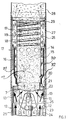
- the training shown consists of a Oil burner of a nozzle assembly 1 with a burner nozzle 2 and attached to a bracket 3 Ignition electrodes 4 has.
- the primary air 11 divides from one by the arrows 12 indicated, by means of a fan, not shown delivered main air flow, with the remaining Residual air as secondary air according to the arrows 13 in the axial direction on the outside of the mixing device 8 flows past and as additional air for the burner flame 14 is used.
- a central device is connected to the mixing device 8 Combustion chamber 15, which is formed by a flame tube 16 is and on their facing away from the mixing device End is open and the burner flame 14 receives.
- the Flame tube 16 is distributed over its length and in shape of circular rings with a large number of passages 17 provided, the passages 17 in the central region of the Flame tube 16 are larger than the other openings, to get more secondary air in at this point to direct the combustion chamber 15.
- a flame brake 19 arranged as a coil body. This prevents the burner flame as a result of the relative strong supply of secondary air from the burner nozzle 2 tears off and in addition a swirl effect exerts the flow components to the combustion of the to promote not yet burned mixture shares and to cause as complete a combustion as possible.
- the end of the flame tube 16 on the burner nozzle side has an outward flange 20 with air passage holes 21 for the passage of the secondary air on.
- the flange 20 is the fixed, closed Disc ring 7 opposite, so that Regulation of the secondary air in the flame tube in axial Direction is displaceable, which is a pipe section 22 has an extension 23 on which a Adjustment rod 24 attacks.
- Section 22 of the flame tube is on the inside of a support tube 25 of the burner slidably mounted.
- the flame tube 16 is circumferentially coaxial with one Annulus 26 for guiding secondary air and surrounded is formed by a tubular element 27 that the flame tube 16 surrounds with a center, closed-walled is formed and from the support tube 25 on which it is mounted with a removable tight fit.
- the tubular element 27 extends over the combustion chamber forming flame tube 16 and carries a tube extension 28, with the help of the rest and axially escaping secondary air is introduced into the residual flame the remaining secondary air is an openwork Flows through the end wall as an aperture 29, the Flame tube is attached. Through the end wall at the same time achieves an accumulation effect in the annular space 26, the entry of secondary air into the combustion chamber 15 allows.
- a closed-walled sleeve-like Separating element 30 arranged so that an inner Annulus 31 and an outer annulus 32 formed is.
- the separating element 30, the length of which is preferred corresponds approximately to half the length of the flame tube 16, is completely open and on at its upper end closed at its other lower end, being it cup-like abuts the flame tube 16. So it is possible, a labyrinth-like supply of secondary air to ensure and this secondary air in the essentially after the deflection via the passages 17 to feed the combustion chamber in the flame tube 16.
- the partition member 30 is almost over the entire length of the combustion chamber 14 arranged so that a deflection of the secondary air only in the end area he follows.
- the function is basically the same Given way, as in the embodiment of FIG. 1st
Landscapes
- Engineering & Computer Science (AREA)
- Chemical & Material Sciences (AREA)
- Combustion & Propulsion (AREA)
- Mechanical Engineering (AREA)
- General Engineering & Computer Science (AREA)
- Physics & Mathematics (AREA)
- Thermal Sciences (AREA)
- Gas Burners (AREA)
Abstract
Description
- Fig. 1
- eine Schnittdarstellung eines Brenners mit Flammrohr und
- Fig. 2
- eine Weitere Ausführungsform eines Brenners.
Claims (5)
- Flammrohrausbildung für Brenner, wie Ölbrenner, von Feuerungsanlagen mit einer der Brennerdüse nachgeordneten, von Primärluft durchströmten Mischeinrichtung, wobei der Außenumfang in axialer Richtung von Sekundärluft durchströmt wird und sich das Flammrohr als Brennkammer mit mantelseitigen Durchtritten anschließt, das durch ein Rohrelement zur Bildung eines zur Brennerseite offenen Ringraumes umgeben ist sowie zur Führung und Abgabe von zusätzlicher Sekundärluft über Durchtritte in das Flammrohr dient, dadurch gekennzeichnet, daß der Ringraum (26) zur labyrintartigen Führung von zugeführter Sekundärluft ein im unteren Bereich verbundenes hülsenartiges Trennelement (30) unter Bildung eines außenliegenden Ringraumes (32) zur Zuführung und einen innenliegenden Ringraumes (31) zur Einführung von Sekundärluft über die Durchtritte (12) in das Flammrohr (16) aufweist.
- Flammrohrausbildung nach Anspruch 1, dadurch gekennzeichnet, daß das hülsenartige Trennelement (30) höhenverstellbar angeordnet ist.
- Flammrohrausbildung nach Anspruch 1 oder 2, dadurch gekennzeichnet, daß das obere Ende des Trennelementes (30) im Bereich der halben Höhe des Ringraumes (26) angeordnet ist.
- Flammrohrausbildung nach einem der Ansprüche 1 bis 3, dadurch gekennzeichnet, daß das obere Ende des Ringraumes (26) durch eine Durchtrittsblende (29) abgeschlossen ist.
- Flammrohrausbildung nach einem der Ansprüche 1 bis 4, dadurch gekennzeichnet, daß die Durchtritte (17) im Flammrohr (16) unterschiedliche Größen aufweisen.
Applications Claiming Priority (2)
| Application Number | Priority Date | Filing Date | Title |
|---|---|---|---|
| DE1998101224 DE19801224A1 (de) | 1998-01-15 | 1998-01-15 | Flammrohrausbildung für Brenner |
| DE19801224 | 1998-01-15 |
Publications (2)
| Publication Number | Publication Date |
|---|---|
| EP0930462A2 true EP0930462A2 (de) | 1999-07-21 |
| EP0930462A3 EP0930462A3 (de) | 2000-01-12 |
Family
ID=7854646
Family Applications (1)
| Application Number | Title | Priority Date | Filing Date |
|---|---|---|---|
| EP98122959A Withdrawn EP0930462A3 (de) | 1998-01-15 | 1998-12-03 | Flammrohrausbildung für Brenner |
Country Status (2)
| Country | Link |
|---|---|
| EP (1) | EP0930462A3 (de) |
| DE (1) | DE19801224A1 (de) |
Cited By (1)
| Publication number | Priority date | Publication date | Assignee | Title |
|---|---|---|---|---|
| EP1500874A2 (de) | 2003-07-21 | 2005-01-26 | J. Eberspächer GmbH & Co. KG | Brenneranordnung für ein Fahrzeugheizgerät |
Citations (1)
| Publication number | Priority date | Publication date | Assignee | Title |
|---|---|---|---|---|
| DE2739149A1 (de) | 1977-08-31 | 1979-03-15 | Kurt Goldammer | Vorrichtung fuer insbesondere oelbrenner von gebaeudefeuerungsanlagen |
Family Cites Families (6)
| Publication number | Priority date | Publication date | Assignee | Title |
|---|---|---|---|---|
| GB893739A (en) * | 1959-05-04 | 1962-04-11 | Colt Ventilation Ltd | Improvements in heat generators |
| AU427595B2 (en) * | 1967-01-20 | 1972-08-30 | Master Consolidated, Inc | Oil burner |
| FR2067648A5 (de) * | 1969-11-12 | 1971-08-20 | Bertin & Cie | |
| US4128388A (en) * | 1977-05-12 | 1978-12-05 | Challenge-Cook Bros., Inc. | Geyseric burner assembly and method for combusting fuels |
| EP0228091A3 (de) * | 1986-01-03 | 1988-08-24 | A/S Kongsberg Väpenfabrikk | In axialer Richtung kompakter Gasturbinenbrenner und Verfahren zu seiner Kühlung |
| WO1988003249A1 (fr) * | 1986-10-27 | 1988-05-05 | Olymp-Werk A. Schwarz Gesellschaft M.B.H. | Bruleur pour la combustion de combustible liquide |
-
1998
- 1998-01-15 DE DE1998101224 patent/DE19801224A1/de not_active Withdrawn
- 1998-12-03 EP EP98122959A patent/EP0930462A3/de not_active Withdrawn
Patent Citations (1)
| Publication number | Priority date | Publication date | Assignee | Title |
|---|---|---|---|---|
| DE2739149A1 (de) | 1977-08-31 | 1979-03-15 | Kurt Goldammer | Vorrichtung fuer insbesondere oelbrenner von gebaeudefeuerungsanlagen |
Cited By (2)
| Publication number | Priority date | Publication date | Assignee | Title |
|---|---|---|---|---|
| EP1500874A2 (de) | 2003-07-21 | 2005-01-26 | J. Eberspächer GmbH & Co. KG | Brenneranordnung für ein Fahrzeugheizgerät |
| EP1500874A3 (de) * | 2003-07-21 | 2008-11-12 | J. Eberspächer GmbH & Co. KG | Brenneranordnung für ein Fahrzeugheizgerät |
Also Published As
| Publication number | Publication date |
|---|---|
| EP0930462A3 (de) | 2000-01-12 |
| DE19801224A1 (de) | 1999-07-22 |
Similar Documents
| Publication | Publication Date | Title |
|---|---|---|
| EP0029619B1 (de) | Brennkammer einer Gasturbine mit Vormisch/Vorverdampf-Elementen | |
| EP0902233B1 (de) | Kombinierte Druckzerstäuberdüse | |
| DE60007946T2 (de) | Eine Brennkammer | |
| DE2345282B2 (de) | Verbrennungseinrichtung für Gasturbinentriebwerke | |
| DE2820702C2 (de) | Brenneranordnung | |
| DE4424599A1 (de) | Verfahren und Vorrichtung zum Betreiben eines kombinierten Brenners für flüssige und gasförmige Brennstoffe | |
| DE2727795A1 (de) | Brennkammer fuer eine gasturbine | |
| EP0780638A2 (de) | Brennkammer für Gasturbinentriebwerke | |
| EP0543323B1 (de) | Brenner für Industrieöfen | |
| DE69507971T2 (de) | Brenner zur Verbrennung von Brennstoff | |
| DE4319213A1 (de) | Brenner zur schnellen und motorunabhängigen Aufheizung eines Abgaskatalysators | |
| DE1198130B (de) | Brenner fuer ringfoermige Brennkammern | |
| EP0483554B1 (de) | Verfahren zur Minimierung der NOx-Emissionen aus einer Verbrennung | |
| EP0346284A2 (de) | Brenner zur Verbrennung von flüssigen Brennstoffen in gasförmigem Zustand | |
| EP0057747B1 (de) | Brenner für die Verbrennung staubförmiger Brennstoffe | |
| DE2558281B2 (de) | Vergasungsbrenner für flüssigen Brennstoff | |
| DE2444188A1 (de) | Brennkammeranordnung mit einem drehbaren topffoermigen brennstoffverteiler | |
| DE202009010692U1 (de) | Mischeinrichtung für einen Brenner | |
| DE19801224A1 (de) | Flammrohrausbildung für Brenner | |
| DE2623759C3 (de) | Druckzerstäuber-Ölbrenner | |
| EP0378517B1 (de) | Brenner zur Verbrennung von gasförmigen Brennstoffen und/oder flüssigen Brennstoffen in gasförmigem Zustand | |
| CH650067A5 (en) | Oil-atomising burner | |
| DE2943289C2 (de) | Brenner für flüssige und/oder gasförmige Brennstoffe, insbesondere für industrielle Öfen | |
| DE4229525A1 (de) | Mischeinrichtung für Ölzerstäubungsbrenner | |
| EP0414050B1 (de) | Verbrennungskopf |
Legal Events
| Date | Code | Title | Description |
|---|---|---|---|
| PUAI | Public reference made under article 153(3) epc to a published international application that has entered the european phase |
Free format text: ORIGINAL CODE: 0009012 |
|
| AK | Designated contracting states |
Kind code of ref document: A2 Designated state(s): AT CH DE DK LI |
|
| AX | Request for extension of the european patent |
Free format text: AL;LT;LV;MK;RO;SI |
|
| PUAL | Search report despatched |
Free format text: ORIGINAL CODE: 0009013 |
|
| AK | Designated contracting states |
Kind code of ref document: A3 Designated state(s): AT BE CH CY DE DK ES FI FR GB GR IE IT LI LU MC NL PT SE |
|
| AX | Request for extension of the european patent |
Free format text: AL;LT;LV;MK;RO;SI |
|
| 17P | Request for examination filed |
Effective date: 20000316 |
|
| AKX | Designation fees paid |
Free format text: AT CH DE DK LI |
|
| STAA | Information on the status of an ep patent application or granted ep patent |
Free format text: STATUS: THE APPLICATION IS DEEMED TO BE WITHDRAWN |
|
| 18D | Application deemed to be withdrawn |
Effective date: 20020702 |