EP0930400B1 - Vorrichtung zum Ausziehen eines Behältnisses aus einem Untergrundschacht - Google Patents
Vorrichtung zum Ausziehen eines Behältnisses aus einem Untergrundschacht Download PDFInfo
- Publication number
- EP0930400B1 EP0930400B1 EP19980403180 EP98403180A EP0930400B1 EP 0930400 B1 EP0930400 B1 EP 0930400B1 EP 19980403180 EP19980403180 EP 19980403180 EP 98403180 A EP98403180 A EP 98403180A EP 0930400 B1 EP0930400 B1 EP 0930400B1
- Authority
- EP
- European Patent Office
- Prior art keywords
- chassis
- articulated
- housing
- cradle
- underground chamber
- Prior art date
- Legal status (The legal status is an assumption and is not a legal conclusion. Google has not performed a legal analysis and makes no representation as to the accuracy of the status listed.)
- Expired - Lifetime
Links
- 238000000605 extraction Methods 0.000 claims description 25
- 210000000481 breast Anatomy 0.000 description 6
- 238000000034 method Methods 0.000 description 3
- 239000000872 buffer Substances 0.000 description 2
- 238000012423 maintenance Methods 0.000 description 2
- 239000002184 metal Substances 0.000 description 2
- 229910052751 metal Inorganic materials 0.000 description 2
- 238000003466 welding Methods 0.000 description 2
- 229910001018 Cast iron Inorganic materials 0.000 description 1
- 238000004891 communication Methods 0.000 description 1
- 239000000284 extract Substances 0.000 description 1
- 238000010348 incorporation Methods 0.000 description 1
- 238000011084 recovery Methods 0.000 description 1
- 238000007789 sealing Methods 0.000 description 1
- 238000013519 translation Methods 0.000 description 1
Images



Classifications
-
- H—ELECTRICITY
- H02—GENERATION; CONVERSION OR DISTRIBUTION OF ELECTRIC POWER
- H02B—BOARDS, SUBSTATIONS OR SWITCHING ARRANGEMENTS FOR THE SUPPLY OR DISTRIBUTION OF ELECTRIC POWER
- H02B1/00—Frameworks, boards, panels, desks, casings; Details of substations or switching arrangements
- H02B1/26—Casings; Parts thereof or accessories therefor
- H02B1/50—Pedestal- or pad-mounted casings; Parts thereof or accessories therefor
- H02B1/505—Pedestal- or pad-mounted casings; Parts thereof or accessories therefor retractable installations
Definitions
- the present invention relates to a device allowing the extraction of a case particularly intended for analog distribution applications or digital signals for telephone networks, for video communication, distribution networks electric, management of traffic lights or terminals fairground, this box being initially contained within a new or existing underground room.
- the present invention therefore aims to overcome these disadvantages by proposing a device which ensures times the extraction of a case from an underground work and its positioning outside the opening area of recovery hatches, in order to guarantee a secure user intervention on the housing mainly considering that the plates of cover can be closed on the structure underground, even when the case is extracted from its pit.
- the device for extracting a housing contained in an underground chamber comprising fixing lugs cooperating with the level of one of the walls of the underground chamber, on which is attached an articulated chassis which allows to extract said housing from said chamber, is characterized by what the chassis is connected at its other end to a supporting cradle the case, this cradle positioning the case outside plumb from the underground chamber, above the ground and at breast height, plates or pads that can then close said underground chamber.
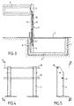
- this one first includes in a masonry work 1 or concrete of civil engineering, equipped with a hatch 2 or a series of hatches commonly called buffers or plates closing, an articulated frame 3 connected on the one hand to fixing lugs 4 integral with one of the walls of the structure, and on the other hand to an articulated cradle 5 on which rests a housing 6.
- the legs of fixing 4 consist of at least one profile metallic cross section, I-shaped, in T, in U, and which rests thanks to a sole 7 added at one of its ends by welding or by means known fixing, on one of the walls 8, 9, preferably a side or bottom wall of the underground structure.
- the sole 7 cooperates rigidly with lugs sealing or by studs with the work in masonry to maintain the profile according to a direction substantially perpendicular to the plane constituted by the bottom or side wall of the pit, to give a rigid seat or support to a chassis 3 which is attached and articulated on at least one profiles 4.
- the underground structure comprises two sections 4, each arranged at an angle and in a plane substantially parallel to one of the walls of side 8 of the book.
- the profile 4 comprises at level of its free end a plurality of orifices 10, 11 radials which allow the passage of axes superimposed 12, 13, these cooperate at the level of a articulated frame 3 formed, according to a first mode of realization, by two parallel connecting rods 14, 15 which are articulated by their other ends at a cradle 5 which supports the housing 6.
- the securing axes 12, 13 of the links 14, 15 to profiles 4 are used to connect the profiles together so as to stiffen the entire assembly.
- the rods 14, 15 form a parallelogram deformable which ensures an extraction movement of the cradle 5 supporting the housing 6 from the inside of the chamber, retaining the verticality in the housing 6.
- the articulated frame 3 is made from two connecting rods 14, 15, one of them being connected to a hinge pin 12 or 13 on profile 4, the other being connected to the free end of the first link 14 or 15 of so as to conform a deformable V, the free end of the second link 14 or 15 being connected to the cradle 5 housing support 6.
- the articulated frame 3 can be doubled using a second profile 4.
- the articulated frame 3 makes it possible to extract the cradle 5 and the box 6 and to place it outside of the plumb of chamber 1, the link or links 14, 15 being placed substantially in line with the profiles of maintenance 4.
- the system of closure includes a plurality of plates or pads that lock together and that don't leave remain that a sufficient opening for the passage of chassis 3 (see figure 3).
- the support cradle 5 of the housing 6 ( Figures 6 and 7) is produced by assembling a plurality of beams 18, 19 or metal profiles which include all first a backrest 20 on which the housing 6 rests and a facade 21 substantially perpendicular to the backsplash, this being connected to the free ends of the chassis articulated 3 by articulation points 22 or rods 14, 15.
- Figure 6 illustrates a particular form of the cradle 5, constituted in particular of two metal profiles 18, 19 arranged parallel and connected at each end, on the one hand to a connecting beam 21, and on the other hand to a facade possibly formed by two vertical arms connected between them by horizontal tie rods or only by a vertical upright.
- the vertical upright (s) 21 or horizontal uprights 18, 19 of the cradle 5 have at one of their ends a plurality of orifices 23, 24 allowing the passage of axes articulation coming from the end of one or rods 14, 15 forming the articulated frame 3.
- the combination of rotational and translation performed by the chassis 3 and the cradle 5 allows to position the housing 6 connected to the cradle 5, in outside of the plumb of the underground chamber 1 and preferably in a lateral position to the underground room above ground.
- kinematics also allow the positioning of the housing at breast height, in a configuration that allows easy, ergonomic and comprehensive intervention security.
- FIG. 8 illustrates a another embodiment of an extraction device subject of the invention.
- the fixing lugs 4 of the articulated frame 3 consist of angles which are connected to one of the side faces 8 of the underground chamber 1, substantially in its upper part.
- a chassis 3 which extracts the box 6 from the underground chamber 1 and which is arranged according to a position substantially perpendicular to the chamber underground 1.
- This chassis 3, developed from a frame of mechanically welded beams 25, is articulated and comprises also an opening assistance system based on cylinders 16, 17 or springs.
- rotation stop devices which lock the articulated frame 3 relative to the fixing lugs 4 in one or other of the configurations (case in the underground chamber and case extracted from the room).
- the articulated frame 3 is provided with a cradle 5 mounted pendulumally at the end of said chassis 3.
- the cradle 5 which supports the housing keeps a position substantially horizontal throughout its travel.
- the cradle 5 pendulum In fully deployed configuration, the cradle 5 pendulum is positioned so as to present the housing at breast height and in a configuration that facilitates user intervention. So by example the cradle 5 box holder 6 will be locked in a preferred direction, on the articulated chassis 3 by any suitable device (stop erasable by spring, pin, stud, ...) to avoid any untimely tipping during intervention.
- an articulated chassis 3 allowing to extract a case 6 from an underground chamber 1, we has on one of the side walls 8 of the chamber two fixing lugs 4 forming a square, each of them being provided with orifices 26 for the passage a connecting pin 27 with an articulated frame 3.
- the ends of the strands of each of the springs 28 rest respectively, on the one hand on the articulated frame 3, and on the other hand on an articulated finger 29 whose amplitude of the stroke can be modified to determine a point of contact between the strand and the finger. So, according to a first setting, between a fully open position and a position fully closed frame, finger and end of the spring strand remain in contact during the entire stroke, which requires the spring to compensate everything along the chassis path.
- the articulated frame 3 has a frame including the backsplash receives a housing 6 which, when the device is fully deployed, comes at breast height and outside the plumb of the underground chamber, preferably on the side, so as to allow almost complete closure by plates or pads to guarantee a safe intervention.
- the device described above offers multiple advantages, it guarantees intervention at breast height in a secure place, it removes the boxes techniques on sidewalks or in common areas of buildings, it allows the incorporation of these boxes techniques in protected areas, including vandalism, due to the use of secure tampons.
Landscapes
- Engineering & Computer Science (AREA)
- Power Engineering (AREA)
- Underground Structures, Protecting, Testing And Restoring Foundations (AREA)
Claims (5)
- Vorrichtung zum Ausziehen eines Behältnisses (6), das in einem Untergrundschacht (1) enthalten ist, wobei die Vorrichtung Befestigungsschienen (4) aufweist, die auf der Höhe einer der Wände (8, 9) des Untergrundschachts (1) zusammenwirken, mit denen einerseits ein angelenktes Untergestell (3) verbunden ist, das das Herausziehen des Behältnisses (6) aus dem Schacht (1) ermöglicht, dadurch gekennzeichnet, daß das Untergestell an seinem anderen Ende mit einer Wiege (5) verbunden ist, die dazu dient, das Behältnis (6) zu halten und es außerhalb des Bereichs senkrecht über dem Untergrundschacht (1) oberhalb des Bodens und auf der Höhe eines Menschen zu positionieren, wobei der Untergrundschacht dann durch Platten oder Stopfen (2) wieder verschlossen werden kann.
- Ausziehvorrichtung nach Anspruch 1, dadurch gekennzeichnet, daß das angelenkte Untergestell (3) mindestens einen Satz von ein Parallelogramm bildenden Schwingarmen (14, 15) aufweist, die einerseits durch Gelenkpunkte (12, 13) mit mindestens einer Befestigungsschiene (4) und andererseits mit einer Wiege (5) verbunden sind, wobei das Untergestell (3) gegebenenfalls mit einem Öffnungs-Hilfssystem mit Zylindern oder Federn (16, 17) versehen ist.
- Ausziehvorrichtung nach Anspruch 1, dadurch gekennzeichnet, daß das angelenkte Untergestell (3) von zwei miteinander ein V bildenden Schwingarmen (14, 15) gebildet ist, von denen der eine durch einen Gelenkpunkt (12) mit einer Befestigungsschiene (4) und der andere einerseits mit dem Ende des ersten Schwingarms und andererseits mit der das Behältnis (6) tragenden Wiege (5) verbunden ist, wobei das Untergestell gegebenenfalls mit einem Öffnungs-Hilfssystem mit Zylindern oder Federn (16, 17) versehen ist.
- Ausziehvorrichtung nach einem der vorangehenden Ansprüche, dadurch gekennzeichnet, daß das angelenkte Untergestell (3) eine pendelnde Wiege (5) aufweist.
- Ausziehvorrichtung nach einem der vorangehenden Ansprüche, dadurch gekennzeichnet, daß das Untergestell (3) an Befestigungsschienen (4), die auf der Höhe der einen der Wände des Untergrundschachts (1) zusammenwirken, mittels eines Systems von Federn (28) angelenkt ist, das an Achsen (27) montiert ist, welche das Untergestell (3) mit den Befestigungsschienen (4) verbinden, wobei ein Fingersystem (29) auf das Ende des einen der Trumms der Federn einwirkt, was die Kompensation des Gewichts der Vorrichtung bei ihrem Herausziehen ermöglicht.
Applications Claiming Priority (2)
| Application Number | Priority Date | Filing Date | Title |
|---|---|---|---|
| FR9716382A FR2772801B1 (fr) | 1997-12-23 | 1997-12-23 | Dispositif d'extraction d'un boitier contenu dans une chambre souterraine |
| FR9716382 | 1997-12-23 |
Publications (2)
| Publication Number | Publication Date |
|---|---|
| EP0930400A1 EP0930400A1 (de) | 1999-07-21 |
| EP0930400B1 true EP0930400B1 (de) | 2003-07-23 |
Family
ID=9515021
Family Applications (1)
| Application Number | Title | Priority Date | Filing Date |
|---|---|---|---|
| EP19980403180 Expired - Lifetime EP0930400B1 (de) | 1997-12-23 | 1998-12-16 | Vorrichtung zum Ausziehen eines Behältnisses aus einem Untergrundschacht |
Country Status (3)
| Country | Link |
|---|---|
| EP (1) | EP0930400B1 (de) |
| DE (1) | DE69816584D1 (de) |
| FR (1) | FR2772801B1 (de) |
Cited By (1)
| Publication number | Priority date | Publication date | Assignee | Title |
|---|---|---|---|---|
| IT202400002608A1 (it) | 2024-02-08 | 2025-08-08 | Giancarlo Pratella | Contenitore per apparati elettrici e simili |
Families Citing this family (3)
| Publication number | Priority date | Publication date | Assignee | Title |
|---|---|---|---|---|
| FR2810807B1 (fr) * | 2000-06-22 | 2004-04-02 | Barat Sa | Borne escamotable pour la distribution electrique dans des lieux publics |
| NL2000407C2 (nl) * | 2006-12-22 | 2008-06-24 | Ingbureauebatech B V | Openbare watervoorziening. |
| CN112713516B (zh) * | 2021-01-08 | 2022-07-05 | 天能电池集团(安徽)有限公司 | 配电柜防水装置 |
Family Cites Families (6)
| Publication number | Priority date | Publication date | Assignee | Title |
|---|---|---|---|---|
| US3029713A (en) * | 1959-05-20 | 1962-04-17 | Marvin H Hopson | Folding and retractable sign |
| FR2580690B1 (fr) * | 1985-04-19 | 1987-06-05 | Tubauto | Barriere escamotable dans le sol utilisable pour la protection de places de parking, voies pietonnieres et analogues |
| US4762439A (en) * | 1987-05-07 | 1988-08-09 | Carlyle Martin P | Security barrier device |
| EP0694433A1 (de) * | 1994-07-29 | 1996-01-31 | Electricite De France | Elektrische Energie-Versorgungsstelle |
| FR2739637A1 (fr) * | 1995-10-09 | 1997-04-11 | Durand Jean Jacques | Renfort d'articulation pour panneau pivotant |
| FR2740484B1 (fr) * | 1995-10-31 | 1998-01-09 | Raison Pure Ind | Dispositif de deplacement d'un element de mobilier urbain et borne de securite positive equipee de ce dispositif |
-
1997
- 1997-12-23 FR FR9716382A patent/FR2772801B1/fr not_active Expired - Fee Related
-
1998
- 1998-12-16 DE DE69816584T patent/DE69816584D1/de not_active Expired - Lifetime
- 1998-12-16 EP EP19980403180 patent/EP0930400B1/de not_active Expired - Lifetime
Cited By (1)
| Publication number | Priority date | Publication date | Assignee | Title |
|---|---|---|---|---|
| IT202400002608A1 (it) | 2024-02-08 | 2025-08-08 | Giancarlo Pratella | Contenitore per apparati elettrici e simili |
Also Published As
| Publication number | Publication date |
|---|---|
| DE69816584D1 (de) | 2003-08-28 |
| FR2772801B1 (fr) | 2000-03-10 |
| EP0930400A1 (de) | 1999-07-21 |
| FR2772801A1 (fr) | 1999-06-25 |
Similar Documents
| Publication | Publication Date | Title |
|---|---|---|
| EP0775377B1 (de) | Technische versorgungseinheit | |
| FR2699208A1 (fr) | Barrière extensible. | |
| EP0930400B1 (de) | Vorrichtung zum Ausziehen eines Behältnisses aus einem Untergrundschacht | |
| FR3028539A1 (fr) | Lame orientable pour toiture exterieure et un dispositif de toiture exterieure muni desdites lames | |
| EP2686489B1 (de) | Einheit aus rahmen und gitter zur abdeckung einer strassenöffnung | |
| FR2508511A1 (fr) | Dispositif de bordure de voie de circulation, notamment de bordure d'autoroute | |
| FR3073887A1 (fr) | Dispositif de securite d`acces a une galerie souterraine. | |
| EP2815036B1 (de) | Wasserdichtes mobiles gebäude bestehend aus mehreren abschnitten | |
| WO2007060307A1 (fr) | Coffre logistique | |
| FR2809752A1 (fr) | Regard a couvercle articule a dispositif antivol, pour excavation de sol | |
| FR2799478A1 (fr) | Dispositif de fermeture de regard de visite ou d'inspection | |
| EP2907772B1 (de) | Sicherheits- und Beladevorrichtung für Abfallsammelstelle | |
| EP1154080A1 (de) | Gelenkige Abdeckung für den polygonalen Rahmen eines Schachts und korrespondierender Schacht | |
| FR2792662A1 (fr) | Dispositif d'obstruction secondaire pour chambre d'acces a un ouvrage souterrain | |
| FR2584112A1 (fr) | Dispositif de securite pour bordure de voie de circulation | |
| FR2495683A1 (fr) | Barriere-ecluse basculante de securite pour plate-forme | |
| FR2799501A1 (fr) | Dispositif pour condamner l'acces inferieur d'une telle echelle a crinoline | |
| EP0259204B1 (de) | Elastische Schranke zum Absperren eines Verkehrsweges | |
| EP0661202A1 (de) | Eine funktionelle, hintere Monoblockzelle für serienmässige Kraftfahrzeugen, und Kraftfahrzeuge damit ausgestattet | |
| FR2759733A1 (fr) | Dispositif pour condamner l'acces aux echelles a crinoline | |
| FR2956684A1 (fr) | Dispositif de fixation d'une plateforme contre une paroi support | |
| FR2529925A1 (fr) | Garde-corps equipe de barreaux verticaux | |
| WO2010109111A1 (fr) | Dispositif de protection de pieds de pylone | |
| FR2713307A1 (fr) | Châssis support escamotable, pour appareillage de sources ou d'émission d'énergies diverses. | |
| FR2789420A1 (fr) | Plate-forme d'echafaudage avec trappe d'acces pour la construction de paroi verticale |
Legal Events
| Date | Code | Title | Description |
|---|---|---|---|
| PUAI | Public reference made under article 153(3) epc to a published international application that has entered the european phase |
Free format text: ORIGINAL CODE: 0009012 |
|
| AK | Designated contracting states |
Kind code of ref document: A1 Designated state(s): BE DE ES GB LU NL |
|
| AX | Request for extension of the european patent |
Free format text: AL;LT;LV;MK;RO;SI |
|
| 17P | Request for examination filed |
Effective date: 19990812 |
|
| AKX | Designation fees paid |
Free format text: BE DE ES GB LU NL |
|
| GRAH | Despatch of communication of intention to grant a patent |
Free format text: ORIGINAL CODE: EPIDOS IGRA |
|
| GRAH | Despatch of communication of intention to grant a patent |
Free format text: ORIGINAL CODE: EPIDOS IGRA |
|
| GRAA | (expected) grant |
Free format text: ORIGINAL CODE: 0009210 |
|
| AK | Designated contracting states |
Designated state(s): BE DE ES GB LU NL |
|
| PG25 | Lapsed in a contracting state [announced via postgrant information from national office to epo] |
Ref country code: NL Free format text: LAPSE BECAUSE OF FAILURE TO SUBMIT A TRANSLATION OF THE DESCRIPTION OR TO PAY THE FEE WITHIN THE PRESCRIBED TIME-LIMIT Effective date: 20030723 Ref country code: GB Free format text: LAPSE BECAUSE OF FAILURE TO SUBMIT A TRANSLATION OF THE DESCRIPTION OR TO PAY THE FEE WITHIN THE PRESCRIBED TIME-LIMIT Effective date: 20030723 |
|
| REG | Reference to a national code |
Ref country code: GB Ref legal event code: FG4D Free format text: NOT ENGLISH |
|
| REF | Corresponds to: |
Ref document number: 69816584 Country of ref document: DE Date of ref document: 20030828 Kind code of ref document: P |
|
| PG25 | Lapsed in a contracting state [announced via postgrant information from national office to epo] |
Ref country code: DE Free format text: LAPSE BECAUSE OF FAILURE TO SUBMIT A TRANSLATION OF THE DESCRIPTION OR TO PAY THE FEE WITHIN THE PRESCRIBED TIME-LIMIT Effective date: 20031024 |
|
| PG25 | Lapsed in a contracting state [announced via postgrant information from national office to epo] |
Ref country code: ES Free format text: LAPSE BECAUSE OF FAILURE TO SUBMIT A TRANSLATION OF THE DESCRIPTION OR TO PAY THE FEE WITHIN THE PRESCRIBED TIME-LIMIT Effective date: 20031103 |
|
| NLV1 | Nl: lapsed or annulled due to failure to fulfill the requirements of art. 29p and 29m of the patents act | ||
| PGFP | Annual fee paid to national office [announced via postgrant information from national office to epo] |
Ref country code: GB Payment date: 20031218 Year of fee payment: 6 |
|
| PGFP | Annual fee paid to national office [announced via postgrant information from national office to epo] |
Ref country code: BE Payment date: 20040116 Year of fee payment: 6 |
|
| GBV | Gb: ep patent (uk) treated as always having been void in accordance with gb section 77(7)/1977 [no translation filed] |
Effective date: 20030723 |
|
| PLBE | No opposition filed within time limit |
Free format text: ORIGINAL CODE: 0009261 |
|
| STAA | Information on the status of an ep patent application or granted ep patent |
Free format text: STATUS: NO OPPOSITION FILED WITHIN TIME LIMIT |
|
| 26N | No opposition filed |
Effective date: 20040426 |
|
| PGFP | Annual fee paid to national office [announced via postgrant information from national office to epo] |
Ref country code: LU Payment date: 20041228 Year of fee payment: 7 |
|
| PG25 | Lapsed in a contracting state [announced via postgrant information from national office to epo] |
Ref country code: BE Free format text: LAPSE BECAUSE OF NON-PAYMENT OF DUE FEES Effective date: 20041231 |
|
| BERE | Be: lapsed |
Owner name: S.A. *BARAT Effective date: 20041231 |
|
| PG25 | Lapsed in a contracting state [announced via postgrant information from national office to epo] |
Ref country code: LU Free format text: LAPSE BECAUSE OF NON-PAYMENT OF DUE FEES Effective date: 20051231 |
|
| BERE | Be: lapsed |
Owner name: S.A. *BARAT Effective date: 20041231 |