EP0930211B1 - Drehgestell für ein neigbares Schienenfahrzeug - Google Patents
Drehgestell für ein neigbares Schienenfahrzeug Download PDFInfo
- Publication number
- EP0930211B1 EP0930211B1 EP99890003A EP99890003A EP0930211B1 EP 0930211 B1 EP0930211 B1 EP 0930211B1 EP 99890003 A EP99890003 A EP 99890003A EP 99890003 A EP99890003 A EP 99890003A EP 0930211 B1 EP0930211 B1 EP 0930211B1
- Authority
- EP
- European Patent Office
- Prior art keywords
- bogie
- swivel
- pendulum
- plates
- bearing
- Prior art date
- Legal status (The legal status is an assumption and is not a legal conclusion. Google has not performed a legal analysis and makes no representation as to the accuracy of the status listed.)
- Expired - Lifetime
Links
Images

Classifications
-
- B—PERFORMING OPERATIONS; TRANSPORTING
- B61—RAILWAYS
- B61F—RAIL VEHICLE SUSPENSIONS, e.g. UNDERFRAMES, BOGIES OR ARRANGEMENTS OF WHEEL AXLES; RAIL VEHICLES FOR USE ON TRACKS OF DIFFERENT WIDTH; PREVENTING DERAILING OF RAIL VEHICLES; WHEEL GUARDS, OBSTRUCTION REMOVERS OR THE LIKE FOR RAIL VEHICLES
- B61F5/00—Constructional details of bogies; Connections between bogies and vehicle underframes; Arrangements or devices for adjusting or allowing self-adjustment of wheel axles or bogies when rounding curves
- B61F5/50—Other details
- B61F5/52—Bogie frames
-
- B—PERFORMING OPERATIONS; TRANSPORTING
- B61—RAILWAYS
- B61F—RAIL VEHICLE SUSPENSIONS, e.g. UNDERFRAMES, BOGIES OR ARRANGEMENTS OF WHEEL AXLES; RAIL VEHICLES FOR USE ON TRACKS OF DIFFERENT WIDTH; PREVENTING DERAILING OF RAIL VEHICLES; WHEEL GUARDS, OBSTRUCTION REMOVERS OR THE LIKE FOR RAIL VEHICLES
- B61F5/00—Constructional details of bogies; Connections between bogies and vehicle underframes; Arrangements or devices for adjusting or allowing self-adjustment of wheel axles or bogies when rounding curves
- B61F5/02—Arrangements permitting limited transverse relative movements between vehicle underframe or bolster and bogie; Connections between underframes and bogies
- B61F5/22—Guiding of the vehicle underframes with respect to the bogies
Definitions
- the invention relates to a bogie for a rail vehicle with a central one Opening having pendulum carrier on the pendulum arms of a Tilt mechanism are articulated and attack pneumatic spring elements.
- Such a bogie can be designed with or without drive. Because of the Tilting mechanism and the multiple suspension required for good handling characteristics When it comes to the design of the individual components, the highest spatial economy is important. But also low weight with sufficient rigidity and manufacturing economy are desirable.
- a generic bogie in which a Pendulum carrier as a substantially cuboid box with a central opening trained and connected by means of pendulum arms with another pendulum carrier.
- one the pendulum carrier is tiltable in the transverse direction, the other is about springs with the Connected to axle beams.
- the breakthrough absorbs the tilt drive.
- bellows-shaped air springs At the two Ends of the pendulum carrier attack bellows-shaped air springs, which because of the load-related considerable volume of air occupy a lot of space.
- the box is relatively heavy and because of its cuboid shape and the downwardly projecting consoles for the articulation of the Swing arms are not designed to be load-bearing. The initiation of the support forces prepares doing special problems.
- Another bogie of the aforementioned type is for example from WO 98/26970 or EP 0 944 513 has become known, which shows a pendulum carrier whose longitudinal ends are arranged via air springs.
- the well-known bogie has also the disadvantage that the required installation space for the air springs is very high.
- US 4,753,174 shows a carrier of a rail vehicle, in which additional Air reservoir is arranged for an air brake system.
- the air reservoirs are going through formed separate chambers, arranged in the carrier chambers, wherein a chamber with an additional air reservoir for normal operation and a chamber with a Air reservoir is provided for emergency operation. Due to the design, the known is suitable Carrier not for use as a pendulum carrier for a rail vehicle, as neither a Opening for a tilt drive still pendulum bearings are provided.
- the pendulum carrier as a tightly welded closed box formed, which forms a pressure vessel, in both sides of the opening Pendulum bearing tubes are tightly welded. So the box can do that for the air springs take up required air volumes. The air springs then need much less Space and can be connected via the box without special lines.
- the on already closed box is closed by the internal pressure and the welded Pendulum bearing tubes further stiffened. The latter also ensure a flawless Force application.
- the box is formed by: two outer and two inner ones over the Length of the box extending web plates, two bulkhead plates, compression straps and Pull straps, wherein the two inner web plates and the two bulkhead plates the central Limit breakthrough and the pendulum bearing tubes each an inner and an outer Connect web plate (claim 2).
- the inner Breakthrough means no weakening of the pendulum carrier.
- the bulkhead plates and the pendulum bearing tubes stiffen the web plates against bending torsional buckling.
- the Switzerlandgurten are respectively welded between inner and outer web plate and close to the Pendulum bearing tubes (claim 3). So they take over the suspension forces directly from the pendulum bearing tubes can be bent according to the force curve and the Weld is easily accessible when the pressure belt is last welded. she By the way, allow the web plates to be fish-bell shaped for further increase in rigidity train.
- a further improvement in the storage of the pendulum arm is achieved by the fact that the Outer rings of the cylindrical roller bearings have grooves, are inserted in the O-rings (Claim 8). Such bearings are standard parts, the grooves for the inclusion of Circlips are determined.
- O-rings By inserting O-rings, a seal of the Lubrication space and ease of assembly achieved, especially if further the Outer rings of the cylindrical roller bearings are mounted in the self-aligning bearing tube with sliding seat (Claim 9).
- the O-rings serve as Verwindhemmung, a separate Anti-rotation is then no longer necessary because of the limited tilting movement.
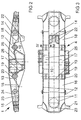
- a pendulum carrier with 1 and a traverse with 2 is designated.
- the pendulum carrier 1 relies on air springs 3 on the only more indicated longitudinal beams of a bogie frame from.
- upper pendulum bearing 4 are provided in which pendulum arms. 5 are pivotally mounted, the other end in lower pendulum bearings 6 of the traverse. 2 is stored.
- the traverse is partially demolished, so that on the right side of the pendulum carrier 1 is completely visible.
- the pendulum carrier 1 is shown alone. He has a in plan view (Fig. 3) recognizable rectangular opening 10 for accommodating the tilt drive on. It forms around the opening 10 around a tightly welded closed Box, which is welded together from the following sheets: one inner web plate 11th and an outer web plate 12 extend over the entire length of the pendulum carrier 1. Den according to registered forces, their outline is fish-bellied. A first Partition plate 13 and a second bulkhead plate 14 connect the two inner web plates eleventh and thus together with these form the opening 10. The partition plates 13, 14 are bent, they run first vertically and approximately horizontally in their lower part. On the top are compression straps 15 with the web plates 11,12 and the bulkhead plates 13,14 welded. The compression straps 15 may be several abutting plates or a only sheet with a central opening 10 be.
- each inner and outer web plate 11,12 are two self-aligning bearing tubes 19th welded, the record the upper pendulum bearing 4. Furthermore, there are between inner and outer tie plates welded 11,12 tension straps, namely a first tension belt 16, the brought from the outside to the pendulum bearing tube 19 and welded to this, a second tension belt 17 of a pendulum bearing tube 19 first down, then horizontally and then guided back up to the other self-aligning bearing tube 19 and welded to it is, and a third tension belt 18 of the other pendulum bearing tube 19 further leads outside. With 20, the weld is designated, with the tension belt 16 with the Pendulum bearing tube 19 is connected. The other tension straps 17,18 are in the same way with the pendulum bearing tube 19 welded. It can be seen that these from below or, if the compression straps are welded on afterwards, also from the top well accessible and is testable.
- outer guide members 21 For outer guide members 21, sword-shaped brackets 22 for the attack of the tilt drive, not shown, Aufstandsplatten 23 for the Air springs 3 with a hole not shown for their connection to the interior of the pressure vessel forming a box 1, and two guide boxes 25.
- Each such is welded tight on each side of the outer web plate and thus forms another Pressure chamber, each having at least one hole 26 with the pressure chamber inside the Pendulum carrier communicates.
- the inner web plates 11 show where they no longer the opening 10 limit, cutouts 24, for weight reduction and the Spaces between the inner and outer web plates 11,12 with the space between the inner web plates 11 to connect fluidly.
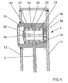
- Figure 4 shows a section through the upper pendulum bearing 4.
- the pendulum bearing tube 19 is a Bearing pin 30 mounted by full complement roller bearing.
- an inner roller bearing 31 and an outer roller bearing 32 are provided, both are For example, double roller bearings known construction.
- the pendulum bearing tube 19 provided with a circumferential groove 33, the bottom in a leading out of the pipe Slot 34 passes. Through this slot is made of several interconnected Slats existing pendulum 5 led out of the pendulum bearing tube 19.
- the bearings 31, 32 have circumferential grooves 35 which are normally for receiving Circlips are used. But here they pick up O-rings 36, which are the ones in the essentially formed by the lubricating holes 37 and their environment spaces caulk. In addition, they cause a sufficient rotation of the Bearing outer rings relative to the pendulum bearing tube 19, when fitted with sliding seat are. Finally, there is an inner disc 38 and a bearing pin 30 with a collar 39th provided, which are clamped together by means of a threaded bolt 40. To this Way is the pendulum 5 between the inner rings of the inner and the outer Roller bearing 31,32 clamped. Since he laterally in the circumferential groove 33 and in the slot 34 is guided, an axial fixing of the bearing pin 30 is not required.
- This arrangement is clean and low-wear and allows a simple way by the way Assembly: after inserting the inner disk 38, the inner roller bearing 31 is first in the Pendulum bearing tube 19 is inserted, then the pendulum arm 5 through the slot 34th inserted and introduced in the sequence of the bearing pin 30. Only then will the outer become Roller bearing 32 inserted and tightened by means of the outer disc 39. This assembly will by the fit sliding fit between the outer rings of the roller bearings 31,32 and the Pendulum bearing tube much easier.
Landscapes
- Engineering & Computer Science (AREA)
- Mechanical Engineering (AREA)
- Bearings For Parts Moving Linearly (AREA)
Description
Claims (9)
- Drehgestell für ein Schienenfahrzeug mit einem eine mittigen Durchbrechung (10) aufweisenden Pendelträger (1), an dem Pendelarme eines Neigemechanismus angelenkt sind und pneumatische Federelemente angreifen, dadurch gekennzeichnet, dass der Pendelträger (1) als dicht geschweißter geschlossener Kasten ausgebildet ist, der einen Druckbehälter bildet, in den beiderseits der Durchbrechung (10) Pendellagerrohre (19) dicht eingeschweißt sind.
- Drehgestell nach Anspruch 1, dadurch gekennzeichnet, dass der Kasten gebildet wird von: zwei inneren (11) und zwei äußeren (12) sich über die Länge des Kastens erstreckende Stegblechen (11,12), zwei Schottblechen (13,14), Druckgurten (15) und Zuggurten (16,17,18), wobei die beiden inneren Stegbleche (11) und die beiden Schottbleche (13,14) den mittigen Durchbruch (10) begrenzen und die Pendellagerrohre (19) jeweils ein inneres (11) und ein äußeres (12) Stegblech verbinden.
- Drehgestell nach Anspruch 2, dadurch gekennzeichnet, dass die Zuggurten (16,17,18) jeweils zwischen innerem (11) und äußerem (12) Stegblech eingeschweißt sind und mittels einer Schweißnaht (20) an die Pendellagerrohre (19) anschließen.
- Drehgestell nach Anspruch 2, dadurch gekennzeichnet, dass die beiden inneren Stegbleche (11) dort, wo sie nicht die Durchbrechung (10) bilden, Ausschnitte (24) aufweisen.
- Drehgestell nach Anspruch 2, dadurch gekennzeichnet, dass an den äußeren Stegblechen (12) Führungskästen (25) dicht angeschweißt sind, die weitere Druckräume begrenzen, die durch Löcher (26) in den äußeren Stegblechen (12) mit dem Inneren des Kastens in Verbindung stehen.
- Drehgestell nach Anspruch 1, dadurch gekennzeichnet, dass in dem Pendellagerrohr (19) ein Lagerbolzen (30) für den Pendelarm (5) mittels zweier Zylinderrollenlager (31,32) gelagert ist, wobei der Pendelarm (5) geschlossene Augen aufweist, mit denen er auf den Lagerbolzen (30) zwischen den beiden Zylinderrollenlagem (31,32) aufgefädelt ist.
- Drehgestell nach Anspruch 6, dadurch gekennzeichnet, dass das Pendellagerrohr (19) einen Umfangsschlitz (34) für den Durchtritt des Pendelarmes (5) aufweist.
- Drehgestell nach Anspruch 7, dadurch gekennzeichnet, dass die Außenringe der Zylinderrollenlager (31,32) Nuten (35) aufweisen, in die O-Ringe (36) eingelegt sind.
- Drehgestell nach Anspruch 8, dadurch gekennzeichnet, dass die Außenring der Zylinderrollenlager (31,32) im Pendellagerrohr (19) mit Schiebesitz montiert sind.
Priority Applications (1)
| Application Number | Priority Date | Filing Date | Title |
|---|---|---|---|
| AT99890003T ATE273823T1 (de) | 1998-01-16 | 1999-01-13 | Drehgestell für ein neigbares schienenfahrzeug |
Applications Claiming Priority (2)
| Application Number | Priority Date | Filing Date | Title |
|---|---|---|---|
| AT0005598A AT406570B (de) | 1998-01-16 | 1998-01-16 | Drehgestell für ein neigbares schienenfahrzeug |
| AT5598 | 1998-02-03 |
Publications (2)
| Publication Number | Publication Date |
|---|---|
| EP0930211A1 EP0930211A1 (de) | 1999-07-21 |
| EP0930211B1 true EP0930211B1 (de) | 2004-08-18 |
Family
ID=3480342
Family Applications (1)
| Application Number | Title | Priority Date | Filing Date |
|---|---|---|---|
| EP99890003A Expired - Lifetime EP0930211B1 (de) | 1998-01-16 | 1999-01-13 | Drehgestell für ein neigbares Schienenfahrzeug |
Country Status (3)
| Country | Link |
|---|---|
| EP (1) | EP0930211B1 (de) |
| AT (2) | AT406570B (de) |
| DE (1) | DE59910230D1 (de) |
Families Citing this family (1)
| Publication number | Priority date | Publication date | Assignee | Title |
|---|---|---|---|---|
| ATE374138T1 (de) | 1998-10-23 | 2007-10-15 | Knorr Bremse Systeme | Bremssystem für ein schienenfahrzeug |
Family Cites Families (6)
| Publication number | Priority date | Publication date | Assignee | Title |
|---|---|---|---|---|
| CH632199A5 (de) * | 1978-09-04 | 1982-09-30 | Schweizerische Lokomotiv | Schienenfahrzeug. |
| IT1183754B (it) | 1985-01-18 | 1987-10-22 | Fiat Ferroviaria Savigliano | Veicolo ferroviario per alte velocita con cassa ad assetto variabile |
| US4753174A (en) * | 1987-07-29 | 1988-06-28 | Amsted Industries Incorporated | Railway vehicle bolster with integral and brake system car reservoir |
| JP2870603B2 (ja) * | 1990-08-13 | 1999-03-17 | 川崎重工業株式会社 | 鉄道振子車両 |
| JPH0773996B2 (ja) * | 1991-08-05 | 1995-08-09 | 財団法人鉄道総合技術研究所 | 鉄道車両用台車枠 |
| IT1253908B (it) * | 1991-12-10 | 1995-08-31 | Firema Ricerche Srl | Carrello ferroviario plurifunzionale |
-
1998
- 1998-01-16 AT AT0005598A patent/AT406570B/de not_active IP Right Cessation
-
1999
- 1999-01-13 AT AT99890003T patent/ATE273823T1/de active
- 1999-01-13 EP EP99890003A patent/EP0930211B1/de not_active Expired - Lifetime
- 1999-01-13 DE DE59910230T patent/DE59910230D1/de not_active Expired - Lifetime
Also Published As
| Publication number | Publication date |
|---|---|
| EP0930211A1 (de) | 1999-07-21 |
| AT406570B (de) | 2000-06-26 |
| ATE273823T1 (de) | 2004-09-15 |
| ATA5598A (de) | 1999-11-15 |
| DE59910230D1 (de) | 2004-09-23 |
Similar Documents
| Publication | Publication Date | Title |
|---|---|---|
| DE69321199T2 (de) | Achsaufhängungssystem | |
| EP0963304B1 (de) | Hinterradaufhängung eines kraftfahrzeuges | |
| DE3812431C2 (de) | ||
| DE2929927C2 (de) | Schienenfahrzeug | |
| EP1231129B1 (de) | Lastfahrzeug | |
| DE2406342C3 (de) | Scherenhebevorrichtung, insbesondere für Kippfahrzeuge | |
| EP0961726A1 (de) | Achslift für luftgefederte fahrzeugachsen | |
| EP1276653B1 (de) | Fahrwerk für ein schienenfahrzeug | |
| EP0930211B1 (de) | Drehgestell für ein neigbares Schienenfahrzeug | |
| DE2711348C2 (de) | Abstützung des Wagenkastens eines Schienenfahrzeuges auf einem Drehgestell | |
| EP1777085B1 (de) | Achsaufhängung für eine längslenkergeführte Fahrzeugachse | |
| DE19630442C1 (de) | Einrichtung zur Querstabilisierung eines Kraftfahrzeuges | |
| EP2991882A1 (de) | Fahrwerksrahmen für ein schienenfahrzeug | |
| DE19548437C1 (de) | Zweiachsiges Schienenfahrzeug-Drehgestell | |
| DE2408187A1 (de) | Schienenfahrzeugaufhaengung | |
| DE3126861C1 (de) | Tankcontainer | |
| DE10143591B4 (de) | Hubladebühnenvorrichtung | |
| DE19940986A1 (de) | Fahrzeugvorderbau mit einem Wasserkasten | |
| CH617135A5 (en) | Rail power unit | |
| DE69709384T2 (de) | Radaufhängung für fahrzeuge | |
| DE3028007C2 (de) | Knickgelenktes Fahrzeug | |
| EP3946987A1 (de) | Militärisches nutzfahrzeug | |
| AT396096B (de) | Sekundaerfederung fuer ein drehgestell eines schienenfahrzeuges | |
| AT409111B (de) | Hinterachsaufhängung für ein nutzfahrzeug | |
| DE19849768B4 (de) | Gabelstapler |
Legal Events
| Date | Code | Title | Description |
|---|---|---|---|
| PUAI | Public reference made under article 153(3) epc to a published international application that has entered the european phase |
Free format text: ORIGINAL CODE: 0009012 |
|
| AK | Designated contracting states |
Kind code of ref document: A1 Designated state(s): AT CH DE DK FR GB LI |
|
| AX | Request for extension of the european patent |
Free format text: AL;LT;LV;MK;RO;SI |
|
| 17P | Request for examination filed |
Effective date: 19991202 |
|
| AKX | Designation fees paid |
Free format text: AT CH DE DK FR GB LI |
|
| 17Q | First examination report despatched |
Effective date: 20030328 |
|
| GRAP | Despatch of communication of intention to grant a patent |
Free format text: ORIGINAL CODE: EPIDOSNIGR1 |
|
| GRAS | Grant fee paid |
Free format text: ORIGINAL CODE: EPIDOSNIGR3 |
|
| GRAA | (expected) grant |
Free format text: ORIGINAL CODE: 0009210 |
|
| AK | Designated contracting states |
Kind code of ref document: B1 Designated state(s): AT CH DE DK FR GB LI |
|
| REG | Reference to a national code |
Ref country code: GB Ref legal event code: FG4D Free format text: NOT ENGLISH |
|
| RAP2 | Party data changed (patent owner data changed or rights of a patent transferred) |
Owner name: SIEMENS TRANSPORTATION SYSTEMS GMBH & CO. KG |
|
| REG | Reference to a national code |
Ref country code: CH Ref legal event code: EP |
|
| REF | Corresponds to: |
Ref document number: 59910230 Country of ref document: DE Date of ref document: 20040923 Kind code of ref document: P |
|
| PG25 | Lapsed in a contracting state [announced via postgrant information from national office to epo] |
Ref country code: DK Free format text: LAPSE BECAUSE OF FAILURE TO SUBMIT A TRANSLATION OF THE DESCRIPTION OR TO PAY THE FEE WITHIN THE PRESCRIBED TIME-LIMIT Effective date: 20041118 |
|
| GBT | Gb: translation of ep patent filed (gb section 77(6)(a)/1977) |
Effective date: 20041220 |
|
| PLBE | No opposition filed within time limit |
Free format text: ORIGINAL CODE: 0009261 |
|
| STAA | Information on the status of an ep patent application or granted ep patent |
Free format text: STATUS: NO OPPOSITION FILED WITHIN TIME LIMIT |
|
| ET | Fr: translation filed | ||
| 26N | No opposition filed |
Effective date: 20050519 |
|
| REG | Reference to a national code |
Ref country code: FR Ref legal event code: CJ Ref country code: FR Ref legal event code: CD Ref country code: FR Ref legal event code: CA |
|
| REG | Reference to a national code |
Ref country code: FR Ref legal event code: PLFP Year of fee payment: 18 |
|
| PGFP | Annual fee paid to national office [announced via postgrant information from national office to epo] |
Ref country code: DE Payment date: 20160321 Year of fee payment: 18 |
|
| PGFP | Annual fee paid to national office [announced via postgrant information from national office to epo] |
Ref country code: AT Payment date: 20151207 Year of fee payment: 18 Ref country code: GB Payment date: 20160111 Year of fee payment: 18 Ref country code: FR Payment date: 20160115 Year of fee payment: 18 |
|
| PGFP | Annual fee paid to national office [announced via postgrant information from national office to epo] |
Ref country code: CH Payment date: 20160404 Year of fee payment: 18 |
|
| REG | Reference to a national code |
Ref country code: DE Ref legal event code: R119 Ref document number: 59910230 Country of ref document: DE |
|
| REG | Reference to a national code |
Ref country code: CH Ref legal event code: PL |
|
| REG | Reference to a national code |
Ref country code: AT Ref legal event code: MM01 Ref document number: 273823 Country of ref document: AT Kind code of ref document: T Effective date: 20170113 |
|
| GBPC | Gb: european patent ceased through non-payment of renewal fee |
Effective date: 20170113 |
|
| REG | Reference to a national code |
Ref country code: FR Ref legal event code: ST Effective date: 20170929 |
|
| PG25 | Lapsed in a contracting state [announced via postgrant information from national office to epo] |
Ref country code: FR Free format text: LAPSE BECAUSE OF NON-PAYMENT OF DUE FEES Effective date: 20170131 Ref country code: LI Free format text: LAPSE BECAUSE OF NON-PAYMENT OF DUE FEES Effective date: 20170131 Ref country code: CH Free format text: LAPSE BECAUSE OF NON-PAYMENT OF DUE FEES Effective date: 20170131 Ref country code: AT Free format text: LAPSE BECAUSE OF NON-PAYMENT OF DUE FEES Effective date: 20170113 |
|
| PG25 | Lapsed in a contracting state [announced via postgrant information from national office to epo] |
Ref country code: DE Free format text: LAPSE BECAUSE OF NON-PAYMENT OF DUE FEES Effective date: 20170801 Ref country code: GB Free format text: LAPSE BECAUSE OF NON-PAYMENT OF DUE FEES Effective date: 20170113 |