EP0928895B1 - Axialkolbenmaschine mit Stützteil - Google Patents
Axialkolbenmaschine mit Stützteil Download PDFInfo
- Publication number
- EP0928895B1 EP0928895B1 EP99100023A EP99100023A EP0928895B1 EP 0928895 B1 EP0928895 B1 EP 0928895B1 EP 99100023 A EP99100023 A EP 99100023A EP 99100023 A EP99100023 A EP 99100023A EP 0928895 B1 EP0928895 B1 EP 0928895B1
- Authority
- EP
- European Patent Office
- Prior art keywords
- stop
- piston machine
- axial piston
- axial
- swivel
- Prior art date
- Legal status (The legal status is an assumption and is not a legal conclusion. Google has not performed a legal analysis and makes no representation as to the accuracy of the status listed.)
- Expired - Lifetime
Links
- 230000002093 peripheral effect Effects 0.000 claims description 9
- 230000001154 acute effect Effects 0.000 claims description 3
- 238000005461 lubrication Methods 0.000 description 9
- 230000005489 elastic deformation Effects 0.000 description 3
- 238000010276 construction Methods 0.000 description 2
- 230000014759 maintenance of location Effects 0.000 description 2
- 230000000694 effects Effects 0.000 description 1
- 230000001050 lubricating effect Effects 0.000 description 1
- 230000004048 modification Effects 0.000 description 1
- 238000012986 modification Methods 0.000 description 1
- 238000010792 warming Methods 0.000 description 1
Images


Classifications
-
- F—MECHANICAL ENGINEERING; LIGHTING; HEATING; WEAPONS; BLASTING
- F04—POSITIVE - DISPLACEMENT MACHINES FOR LIQUIDS; PUMPS FOR LIQUIDS OR ELASTIC FLUIDS
- F04B—POSITIVE-DISPLACEMENT MACHINES FOR LIQUIDS; PUMPS
- F04B1/00—Multi-cylinder machines or pumps characterised by number or arrangement of cylinders
- F04B1/12—Multi-cylinder machines or pumps characterised by number or arrangement of cylinders having cylinder axes coaxial with, or parallel or inclined to, main shaft axis
- F04B1/122—Details or component parts, e.g. valves, sealings or lubrication means
- F04B1/124—Pistons
- F04B1/126—Piston shoe retaining means
Definitions
- the invention has for its object in an axial piston machine present type constraints between the retraction device and the support member avoid and still ensure a safe support.
- the distance is independent of the swivel angle of the swivel plate. This results in a Contact between the retraction device and the stop only with an axial Overloading the retraction device, with the retraction device at the stop is supported and stabilized.
- the axial distance is preferably only so large that the Retraction device for a large axial load or overload by the Retraction forces against the stop before the retractor over their deformed elastic deformation range or beyond its yield strength or is bent. This ensures that the retraction device only Load peaks come into contact with the support envelope and then are effectively supported becomes. When the load or overload ceases, the retractor returns due to their elasticity back to their starting position.
- the configuration according to the invention is distinguished characterized in that the distance between the retraction device and the stop in entire swivel range of the swivel plate is essentially the same.
- the stop can be rounded and / or have the shape of a stop ridge.
- the stop can have a shape that is applied to the stop ridge Flanks is limited, of which one flank is essentially parallel to the Support plane of the swivel plate extends in its zero position and the other flank itself parallel to the support plane of the swivel plate in its maximum swiveled-out position extends.
- An advantageous form of the support part is given when the one flank in lies on a transverse plane and the other flank is around the first flank maximum swivel angle is angled towards the cylinder drum.
- the stop ridge can laterally with respect to an axial plane containing the pivot axis or other side may be offset or spaced.
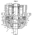
- the main parts of the axial piston machine are a housing 2 with a housing wall 2a visible in section in the drawing, the one Encloses interior 3, in which a cylinder drum 5 with a shaft 4 several, preferably distributed on a pitch circle and directed longitudinally Cylinder bores 6 is arranged, a plurality of pistons 7, which are in the cylinder bores 6 are axially displaceable, a plurality of sliding shoes 8 which are pivotable, but axially fixedly connected to spherical piston heads 9 at one end of the pistons 7, a swash plate 11, on the inclined surface 12 of the sliding shoes 8 and axially are supported, the swivel plate 11 about a right angle to the longitudinal central axis the axial piston machine 1 or the axis of rotation 13 of the shaft 4 Swivel axis 14 in a swivel bearing 14a by an adjustment device (not shown) is pivotable and is lockable in the respective pivot position, a retraction device 15, the purpose of which is to place the sliding
- the retraction device 15 is through a perforated disc 22 in the number of Sliding shoes 8 existing holes 23 formed, the edges of the holes, the sliding shoes 8 in Area surrounded by tapered glide heads with play and with their Swivel plate 11 facing side on a foot flange 24 of the associated Slide shoe 8 abut so that the foot flange 24 with little movement between the inclined surface 12 and the perforated disc 22 is held.
- the perforated disc 22 itself on its side facing away from the swivel plate 11 on a spherical ring section Bearing surface on an inner support ring 26.
- the retention device 16 is mirrored by one or two each other oppositely arranged and formed support parts 31 formed in the area project the pivot axis 14 radially inward from the peripheral wall 2a of the housing 2 and engage the retraction device 15 with an axial distance a.
- the support parts 31 are preferably separate components which are fastened on the inside to the peripheral wall 2a, preferably by screws 32. It is advantageous to position the Support parts 31 radial and preferably also axial positioning surfaces 33a, 33b on the Provide peripheral wall 2a, on which the support members 31 with corresponding surfaces abut and in particular are positioned axially so that the screws 32 in the positively positioned position of the support members 31 fulfill their fastening function.
- the support parts 31 have a radially inwardly projecting support leg 31a and a axially extending support leg 31b angularly shaped, above the screws 32 through the peripheral wall 2a from the outside in through holes 34 and in Hold threaded holes 35 in the support parts 31, here in the support legs 31b.
- the Screw heads 32a are preferably in extensions of the through holes 34 arranged sunk.
- the positioning surfaces 33a, 33b are through recesses 33c in the form of cylindrical sections in the inner surface of the peripheral wall 2a formed, the ends of the swivel plate 11 facing each by a radial step surface forming the associated positioning surface 33a is limited.
- the Recesses 33c are in the axial direction facing the cylinder drum 5 open.
- the distance a is small and can be about a few tenths of a millimeter to about 1 mm or up be about 2 mm.
- the size of the distance a depends on the flexibility of the Construction.
- the distance a is at a maximum such that the retraction device 15 in the event of an axial overload in the direction of the retaining device 16 against the latter generally designated 36 stop on the associated support member 31 before the Retraction device 15 beyond their elastic deformation range or beyond their Yield point is deformed or bent.
- the stop 36 can be rounded by a Be formed stop surface, the radial distance ra to the pivot axis 14 in the Swinging direction of the swash plate 11 increases. Hikes in this configuration the anchor point when swiveling outwards and swiveling back again Inside.
- the or the support parts 31 have one in their central region radially extending rounded or angular stop projection or stop ridge 36a, which is preferably located in the central swivel range and from which can extend to both sides stop flanks 36b, 36c, one of which Stop flank 36b extends approximately at right angles to the axis of rotation 13 and the other Stop flank 36c is approximately parallel to the swivel plate 11 in its maximum Swing position extends.
- the stop flank 36b extends approximately parallel to the Back surface 37 of the retaining device 16 or perforated disk 22 in its zero position, and the stop flank 36c extends parallel to the back surface 37 at the maximum Pivotal position of the retraction device 15.
- the of the stop flanks 36b, 36c included, open to the cylinder drum 5 angle is denoted by b.
- the Offset of the stop 36 or stop ridge 36a with respect to the pivot axis 14 and the longitudinal center plane E containing the axis of rotation 13 is denoted by V.
- the distance a remains in all Pivotal positions of the swivel plate 11 are essentially the same.
- the recesses 33c also correspond to the offset V of the stop ridge 36a offset with respect to the longitudinal center plane E. 4 and 5 is a the tilting moment resulting from the stop is limited to an average value.
- the stop flanks 36b, 36c can be one indicated acute angle c with the back surface 37 in the zero position and in the maximum Include swivel position up to about 5 °, e.g. B. can be about 0.5 to 5 °.
- the axial distance a remains in each Swivel position of the swivel plate 11 is the same size.
- the last one described Modification with the angle c has the advantage that in the functional mode Overload a hydrodynamic lubricating film between the respective stop flank 26b, 26c and the back surface 37 can build, which improves the lubrication will reduce friction and wear.
- the axial piston machine 1 consists in a Device 41 for automatic lubrication of the rotating shaft 13 on both sides Swivel bearing 42.
- the lubrication device 41 has lubrication channels 43 which differ from the sliding surface 12, in particular of known, in the foot surface of the sliding shoes 8 existing pressure pockets, extend to the pivot bearings 42.
- This improved lubrication enables the pivot bearings 42 to be formed by plain bearings with plain bearing shells 46, as shown in FIG. 1. It is also advantageous if the lubrication channels 43 in the circumferential direction of the Open pivot bearing 42 extending lubrication grooves 44.
- the load peaks described above can occur both when the pistons 7 exert a tensile force on the retraction device 15 and / or then, if there is an increased leakage oil pressure or an increased interior pressure that exists between the Slip shoes 8 and the swivel plate 11 takes effect, the slide shoes 8 from the Seek to remove the swivel plate 11.
Landscapes
- Engineering & Computer Science (AREA)
- Mechanical Engineering (AREA)
- General Engineering & Computer Science (AREA)
- Reciprocating Pumps (AREA)
- Compressor (AREA)
Description
- Fig. 1
- eine erfindungsgemäße Axialkolbenmaschine im axialen Schnitt;
- Fig. 2
- die Axialkolbenmaschine in der Draufsicht;
- Fig. 3
- den Teilschnitt III-III in Fig. 1 in der Nullstellung der Axialkolbenmaschine;
- Fig. 4
- den Teilschnitt III-III in der Nullstellung der Axialkolbenmaschine in abgewandelter Ausgestaltung; und
- Fig. 5
- den Teilschnitt III-III in der Nullstellung der Axialkolbenmaschine in weiter abgewandelter Ausgestaltung.
Claims (11)
- Axialkolbenmaschine (1) mit einem Gehäuse (2), in dessen Gehäuseinnenraum (3) eine Zylindertrommel (5) gelagert ist, in welcher mehrere, etwa axial verlaufende Zylinderbohrungen (6) ausgebildet sind, in welchen Kolben (7) bewegbar geführt sind, die sich über Gleitschuhe (8) an einer um eine Schwenkachse (14) schwenkbare Schwenkscheibe (11) abstützen, mit einer Rückzugeinrichtung (15), an welcher sich die Gleitschuhe (8) bei der Rückzugbewegung der Kolben (7) abstützen, und die einen Abstand (ra) von der Schwenkachse (14) aufweist, und mit wenigstens einem am Gehäuse angeordneten Stützteil (31) zum Abstützen der Rückzugeinrichtung (15) am Gehäuse (2), wobei das Stützteil (31) im Bereich der Schwenkachse (14) der Schwenkscheibe (11) zumindest auf der Seite der Axialkolbenmaschine (1) angeordnet ist, auf der die Kolben (7) einen Saughub ausführen, wobei das Stützteil (31) einen von der Rückzugeinrichtung (15) beabstandeten Anschlag (36) aufweist und wobei der axiale Abstand (a) zwischen der Rückzugeinrichtung (15) und dem Anschlag (36) im wesentlichen unabhängig vom Schwenkwinkel der Schwenkscheibe (11) ist.
- Axialkolbenmaschine nach Anspruch 1,
dadurch gekennzeichnet, daß der axiale Abstand (a) nur so groß ist, daß die Rückzugeinrichtung bei einer axialen Überlastung gegen den Anschlag (36) stößt, bevor sie über ihre Elastizitätsgrenze hinaus verformt oder verbogen wird. - Axialkolbenmaschine nach Anspruch 1 oder 2,
dadurch gekennzeichnet, daß der Anschlag (36) im Winkelbereich eines zur Zylindertrommel (5) hin offenen Winkels (b) liegt, dessen einer Schenkel (36b) sich parallel zur Schwenkscheibe (11) in deren Nullstellung erstreckt und dessen anderer Schenkel (36c) sich etwa parallel zur Schwenkscheibe (11) in deren maximalen Schwenkstellung erstreckt. - Axialkolbenmaschine nach einem der vorherigen Ansprüche 1 bis 3,
dadurch gekennzeichnet, daß der Anschlag (36) eine der Rückzugeinrichtung (15) zugewandte Anschlagfläche hat, die konvex gerundet ist. - Axialkolbenmaschine nach einem der vorherigen Ansprüche 1 bis 4,
dadurch gekennzeichnet, daß der Anschlag (36) einen gerundeten oder kantenförmigen Anschlagfirst (36a) aufweist, von dem sich nach beiden Seiten Anschlagflanken (36b, 36c) erstrecken, von denen die eine Anschlagflanke (36b) sich parallel zur Schwenkscheibe (11) in deren Nullstellung erstreckt oder mit dieser einen spitzen Winkel (c) von bis vorzugsweise etwa 5° einschließt und die andere Anschlagflanke (36c) sich parallel zur Schwenkscheibe (11) in deren maximalen Schwenkstellung erstreckt oder mit dieser einen spitzen Winkel (c) von bis vorzugsweise etwa 5° einschließt. - Axialkolbenmaschine nach einem der vorherigen Ansprüche 1 bis 5,
dadurch gekennzeichnet, daß der Anschlag (36) oder Anschlagfirst (36a) bezüglich einer axialen, die Schwenkachse (14) und vorzugsweise auch die Drehachse (13) der Zylindertrommel (5) enthaltenden Ebene (E) quer versetzt (Fig. 3) oder beabstandet (Fig. 4 und 5) ist. - Axialkolbenmaschine nach einem der vorherigen Ansprüche 1 bis 6,
dadurch gekennzeichnet, daß Stützteil (31) ein separates Bauteil ist, daß innen an der Umfangswand (2a) des Gehäuses (2) befestigt ist. - Axialkolbenmaschine nach Anspruch 7,
dadurch gekennzeichnet, daß die Umfangswand (2a) eine radiale Positionierfläche (33a) zum Positionieren des Stützteils (31) in Richtung auf die Rückzugeinrichtung (15) und vorzugsweise auch eine axiale Positionierfläche (33b) zur Positionierung des Stützteils (31) radial nach außen aufweist. - Axialkolbenmaschine nach Anspruch 7 oder 8,
dadurch gekennzeichnet, daß das Stützteil (31) durch eine Schraube (32) mit der Umfangswand (2a) verschraubt ist, wobei die Schraube (32) vorzugsweise von außen eingeschraubt ist. - Axialkolbenmaschine nach einem der vorherigen Ansprüche 1 bis 9,
dadurch gekennzeichnet, daß das Stützteil (31) mit einem sich radial nach innen erstreckenden Anschlagschenkel (31a) und einem sich etwa achsparallel erstreckenden Befestigungsschenkel (31b) winkelförmig geformt ist. - Axialkolbenmaschine nach einem der vorherigen Ansprüche 7 bis 10,
dadurch gekennzeichnet, daß das Stützteil (31) in einer sich achsparallel erstreckenden Ausnehmung (33c) in der Umfangswand (2a) sitzt, wobei die Ausnehmung (33c) vorzugsweise eine kreisabschnittförmige Querschnittsform aufweist und das Stützteil (31) mit einer entsprechenden kreisabschnittsförmigen Rundung in der Ausnehmung (33c) sitzt.
Applications Claiming Priority (2)
| Application Number | Priority Date | Filing Date | Title |
|---|---|---|---|
| DE19800631 | 1998-01-09 | ||
| DE19800631A DE19800631A1 (de) | 1998-01-09 | 1998-01-09 | Axialkolbenmaschine mit Stützteil |
Publications (3)
| Publication Number | Publication Date |
|---|---|
| EP0928895A2 EP0928895A2 (de) | 1999-07-14 |
| EP0928895A3 EP0928895A3 (de) | 2001-03-28 |
| EP0928895B1 true EP0928895B1 (de) | 2004-07-14 |
Family
ID=7854267
Family Applications (1)
| Application Number | Title | Priority Date | Filing Date |
|---|---|---|---|
| EP99100023A Expired - Lifetime EP0928895B1 (de) | 1998-01-09 | 1999-01-04 | Axialkolbenmaschine mit Stützteil |
Country Status (2)
| Country | Link |
|---|---|
| EP (1) | EP0928895B1 (de) |
| DE (2) | DE19800631A1 (de) |
Families Citing this family (5)
| Publication number | Priority date | Publication date | Assignee | Title |
|---|---|---|---|---|
| DE19947321A1 (de) * | 1999-10-01 | 2001-04-19 | Brueninghaus Hydromatik Gmbh | Axialkolbenmaschine mit einer Rückzugeinrichtung |
| DE10035630C1 (de) | 2000-07-21 | 2002-03-14 | Brueninghaus Hydromatik Gmbh | Axialkolbenmaschine mit einer Rückzugeinrichtung |
| DE10312242B3 (de) * | 2003-03-19 | 2004-12-02 | Brueninghaus Hydromatik Gmbh | Druckstift und Axialkolbenmaschinen mit diesem Druckstift |
| DE102007030708A1 (de) * | 2007-07-02 | 2009-01-08 | Robert Bosch Gmbh | Axialkolbenmaschine mit Drosselnut |
| DE102024210560A1 (de) * | 2024-11-04 | 2026-05-07 | Robert Bosch Gesellschaft mit beschränkter Haftung | Verstellbare Axialkolbenmaschine in Schrägscheibenbauweise und Antriebsvorrichtung damit |
Family Cites Families (6)
| Publication number | Priority date | Publication date | Assignee | Title |
|---|---|---|---|---|
| US3587403A (en) * | 1970-01-16 | 1971-06-28 | Sperry Rand Corp | Power transmission |
| US3605565A (en) * | 1970-03-13 | 1971-09-20 | Sperry Rand Corp | Power transmission |
| US4443160A (en) * | 1980-11-13 | 1984-04-17 | Brueninghaus Hydraulik Gmbh | High-pressure piston pump for liquids, preferably for water |
| DE3212402A1 (de) * | 1982-04-02 | 1983-10-13 | Abex Corp., 10036 New York, N.Y. | Hydraulische axialkolbenmaschine |
| US4455920A (en) * | 1982-06-01 | 1984-06-26 | Abex Corporation | Rocker cam control |
| DE3901064A1 (de) * | 1988-01-16 | 1989-07-27 | Michael Meyerle | Hydrostatische axialkolbenmaschine, insbesondere fuer ein kraftfahrzeuggetriebe mit leistungsverzweigung |
-
1998
- 1998-01-09 DE DE19800631A patent/DE19800631A1/de not_active Withdrawn
-
1999
- 1999-01-04 EP EP99100023A patent/EP0928895B1/de not_active Expired - Lifetime
- 1999-01-04 DE DE59909922T patent/DE59909922D1/de not_active Expired - Lifetime
Also Published As
| Publication number | Publication date |
|---|---|
| EP0928895A2 (de) | 1999-07-14 |
| EP0928895A3 (de) | 2001-03-28 |
| DE59909922D1 (de) | 2004-08-19 |
| DE19800631A1 (de) | 1999-07-15 |
Similar Documents
| Publication | Publication Date | Title |
|---|---|---|
| EP0162238B1 (de) | Axialkolbenmaschine, insbesondere -pumpe der Schrägscheiben- bauart | |
| EP1474617B1 (de) | Kolbenmaschine oder drehgleitlagerung | |
| EP2038890A2 (de) | Axialkolbenmaschine mit einer ansatzscheibe an einer rückhaltescheibe, entsprechende rückhaltescheibe und entsprechende ansatzscheibe | |
| EP1886035B1 (de) | Schrägscheiben-schwenklager | |
| DE4237506C2 (de) | Axialkolbenmaschine | |
| DE3434421A1 (de) | Selbsttaetig rueckstellbare bremsbacke fuer teilbelag-scheibenbremsen | |
| EP2094980A2 (de) | Lagerschale für eine hydrostatische maschine und hydrostatische maschine mit dieser lagerschale | |
| DE2031511C3 (de) | Mechanische Betätigungsvorrichtung für Fahrzeuginnenbackenbremsen | |
| DE69922380T2 (de) | Radnaben und bremsscheibenanordnung für schwerfahrzeug | |
| EP1474616B1 (de) | Drehgleitlager | |
| EP1301709B1 (de) | Axialkolbenmaschine mit einer rückzugeinrichtung | |
| EP0928895A2 (de) | Axialkolbenmaschine mit Stützteil | |
| EP0346716A1 (de) | Kolben-Zylinder-Einheit mit gegen Verdrehung gesicherter Kolbenstange | |
| EP1157211B1 (de) | Axialkolbenmaschine | |
| DE10220610A1 (de) | Drehgleitlager | |
| DE2840465C2 (de) | ||
| WO2000075511A1 (de) | Schrägscheiben-schwenklager | |
| DE3503437C2 (de) | Axial-Kolbenmaschine | |
| EP0401706B1 (de) | Teilbelag-Scheibenbremse mit Schwimmsattel | |
| DE2220164C3 (de) | Reiheneinspritzpumpe für Brennkraftmaschinen | |
| EP0921312B1 (de) | Axialkolbenmaschine | |
| DE3918011C2 (de) | Niederhaltefeder für Teilbelag-Scheibenbremsen und zugehöriges Gehäuse | |
| EP1287232B1 (de) | Axialkolbenmaschine | |
| EP0305521B1 (de) | Kolben für verbrennungsmotoren | |
| DE1949866A1 (de) | Schwimmsattelscheibenbremse |
Legal Events
| Date | Code | Title | Description |
|---|---|---|---|
| PUAI | Public reference made under article 153(3) epc to a published international application that has entered the european phase |
Free format text: ORIGINAL CODE: 0009012 |
|
| AK | Designated contracting states |
Kind code of ref document: A2 Designated state(s): DE FR GB IT SE |
|
| AX | Request for extension of the european patent |
Free format text: AL;LT;LV;MK;RO;SI |
|
| PUAL | Search report despatched |
Free format text: ORIGINAL CODE: 0009013 |
|
| AK | Designated contracting states |
Kind code of ref document: A3 Designated state(s): AT BE CH CY DE DK ES FI FR GB GR IE IT LI LU MC NL PT SE |
|
| AX | Request for extension of the european patent |
Free format text: AL;LT;LV;MK;RO;SI |
|
| 17P | Request for examination filed |
Effective date: 20010503 |
|
| AKX | Designation fees paid |
Free format text: DE FR GB IT SE |
|
| GRAP | Despatch of communication of intention to grant a patent |
Free format text: ORIGINAL CODE: EPIDOSNIGR1 |
|
| GRAS | Grant fee paid |
Free format text: ORIGINAL CODE: EPIDOSNIGR3 |
|
| GRAA | (expected) grant |
Free format text: ORIGINAL CODE: 0009210 |
|
| AK | Designated contracting states |
Kind code of ref document: B1 Designated state(s): DE FR GB IT SE |
|
| REG | Reference to a national code |
Ref country code: GB Ref legal event code: FG4D Free format text: NOT ENGLISH |
|
| REF | Corresponds to: |
Ref document number: 59909922 Country of ref document: DE Date of ref document: 20040819 Kind code of ref document: P |
|
| GBT | Gb: translation of ep patent filed (gb section 77(6)(a)/1977) |
Effective date: 20040907 |
|
| REG | Reference to a national code |
Ref country code: SE Ref legal event code: TRGR |
|
| ET | Fr: translation filed | ||
| PLBE | No opposition filed within time limit |
Free format text: ORIGINAL CODE: 0009261 |
|
| STAA | Information on the status of an ep patent application or granted ep patent |
Free format text: STATUS: NO OPPOSITION FILED WITHIN TIME LIMIT |
|
| 26N | No opposition filed |
Effective date: 20050415 |
|
| PGFP | Annual fee paid to national office [announced via postgrant information from national office to epo] |
Ref country code: SE Payment date: 20091222 Year of fee payment: 12 |
|
| PGFP | Annual fee paid to national office [announced via postgrant information from national office to epo] |
Ref country code: IT Payment date: 20100125 Year of fee payment: 12 Ref country code: FR Payment date: 20100209 Year of fee payment: 12 |
|
| PGFP | Annual fee paid to national office [announced via postgrant information from national office to epo] |
Ref country code: GB Payment date: 20100121 Year of fee payment: 12 |
|
| REG | Reference to a national code |
Ref country code: SE Ref legal event code: EUG |
|
| GBPC | Gb: european patent ceased through non-payment of renewal fee |
Effective date: 20110104 |
|
| REG | Reference to a national code |
Ref country code: FR Ref legal event code: ST Effective date: 20110930 |
|
| PG25 | Lapsed in a contracting state [announced via postgrant information from national office to epo] |
Ref country code: FR Free format text: LAPSE BECAUSE OF NON-PAYMENT OF DUE FEES Effective date: 20110131 |
|
| PG25 | Lapsed in a contracting state [announced via postgrant information from national office to epo] |
Ref country code: GB Free format text: LAPSE BECAUSE OF NON-PAYMENT OF DUE FEES Effective date: 20110104 |
|
| PG25 | Lapsed in a contracting state [announced via postgrant information from national office to epo] |
Ref country code: IT Free format text: LAPSE BECAUSE OF NON-PAYMENT OF DUE FEES Effective date: 20110104 |
|
| PG25 | Lapsed in a contracting state [announced via postgrant information from national office to epo] |
Ref country code: SE Free format text: LAPSE BECAUSE OF NON-PAYMENT OF DUE FEES Effective date: 20110105 |
|
| PGFP | Annual fee paid to national office [announced via postgrant information from national office to epo] |
Ref country code: DE Payment date: 20130326 Year of fee payment: 15 |
|
| REG | Reference to a national code |
Ref country code: DE Ref legal event code: R119 Ref document number: 59909922 Country of ref document: DE |
|
| REG | Reference to a national code |
Ref country code: DE Ref legal event code: R119 Ref document number: 59909922 Country of ref document: DE Effective date: 20140801 |
|
| PG25 | Lapsed in a contracting state [announced via postgrant information from national office to epo] |
Ref country code: DE Free format text: LAPSE BECAUSE OF NON-PAYMENT OF DUE FEES Effective date: 20140801 |