EP0927306B1 - Pompe peristaltique portable - Google Patents
Pompe peristaltique portable Download PDFInfo
- Publication number
- EP0927306B1 EP0927306B1 EP97937395A EP97937395A EP0927306B1 EP 0927306 B1 EP0927306 B1 EP 0927306B1 EP 97937395 A EP97937395 A EP 97937395A EP 97937395 A EP97937395 A EP 97937395A EP 0927306 B1 EP0927306 B1 EP 0927306B1
- Authority
- EP
- European Patent Office
- Prior art keywords
- rotor
- module
- roller
- peristaltic pump
- tubing
- Prior art date
- Legal status (The legal status is an assumption and is not a legal conclusion. Google has not performed a legal analysis and makes no representation as to the accuracy of the status listed.)
- Expired - Lifetime
Links
Images


Classifications
-
- F—MECHANICAL ENGINEERING; LIGHTING; HEATING; WEAPONS; BLASTING
- F04—POSITIVE - DISPLACEMENT MACHINES FOR LIQUIDS; PUMPS FOR LIQUIDS OR ELASTIC FLUIDS
- F04B—POSITIVE-DISPLACEMENT MACHINES FOR LIQUIDS; PUMPS
- F04B43/00—Machines, pumps, or pumping installations having flexible working members
- F04B43/12—Machines, pumps, or pumping installations having flexible working members having peristaltic action
- F04B43/1253—Machines, pumps, or pumping installations having flexible working members having peristaltic action by using two or more rollers as squeezing elements, the rollers moving on an arc of a circle during squeezing
-
- A—HUMAN NECESSITIES
- A61—MEDICAL OR VETERINARY SCIENCE; HYGIENE
- A61M—DEVICES FOR INTRODUCING MEDIA INTO, OR ONTO, THE BODY; DEVICES FOR TRANSDUCING BODY MEDIA OR FOR TAKING MEDIA FROM THE BODY; DEVICES FOR PRODUCING OR ENDING SLEEP OR STUPOR
- A61M5/00—Devices for bringing media into the body in a subcutaneous, intra-vascular or intramuscular way; Accessories therefor, e.g. filling or cleaning devices, arm-rests
- A61M5/14—Infusion devices, e.g. infusing by gravity; Blood infusion; Accessories therefor
- A61M5/142—Pressure infusion, e.g. using pumps
- A61M5/14212—Pumping with an aspiration and an expulsion action
- A61M5/14232—Roller pumps
-
- A—HUMAN NECESSITIES
- A61—MEDICAL OR VETERINARY SCIENCE; HYGIENE
- A61M—DEVICES FOR INTRODUCING MEDIA INTO, OR ONTO, THE BODY; DEVICES FOR TRANSDUCING BODY MEDIA OR FOR TAKING MEDIA FROM THE BODY; DEVICES FOR PRODUCING OR ENDING SLEEP OR STUPOR
- A61M2205/00—General characteristics of the apparatus
- A61M2205/12—General characteristics of the apparatus with interchangeable cassettes forming partially or totally the fluid circuit
-
- A—HUMAN NECESSITIES
- A61—MEDICAL OR VETERINARY SCIENCE; HYGIENE
- A61M—DEVICES FOR INTRODUCING MEDIA INTO, OR ONTO, THE BODY; DEVICES FOR TRANSDUCING BODY MEDIA OR FOR TAKING MEDIA FROM THE BODY; DEVICES FOR PRODUCING OR ENDING SLEEP OR STUPOR
- A61M5/00—Devices for bringing media into the body in a subcutaneous, intra-vascular or intramuscular way; Accessories therefor, e.g. filling or cleaning devices, arm-rests
- A61M5/14—Infusion devices, e.g. infusing by gravity; Blood infusion; Accessories therefor
- A61M5/142—Pressure infusion, e.g. using pumps
- A61M5/14244—Pressure infusion, e.g. using pumps adapted to be carried by the patient, e.g. portable on the body
Definitions
- the present invention relates to portable peristaltic pumps. She relates more particularly to a miniature peristaltic pump for injection of drug solutions.
- Miniature pumps or micropumps for medical use are known for several years. Light and small, they are worn by the patient discreetly and without discomfort and allow him administer, subcutaneously or intravenously, continuously or as directed determined program, controlled quantities of solutions without being bedridden and connected to a device bulky, expensive and noisy.
- Such pumps are most often of the rotary peristaltic type, the principle consists in having a deformable plastic pipe connected to a tank containing the solution and crush it locally against a part support of rounded shape by means of pressure rollers mounted on a rotor driven by a motor acting through a gear train. The liquid is thus sucked from the reservoir and discharged towards the outlet to be injected in the patient.
- EP 388 787, EP 447 909, EP 521 184 and WO 94/06491 describe miniature peristaltic pumps of this type.
- JP 58 070079 describes, moreover, a peristaltic pump provided a declutching system for uncoupling the motor and the pump to make it run faster by manual action. It is necessary however note that declutching is done by actuation in translation a control rod, which makes the operation impractical.
- Patent EP 388,787 shows a support piece having the shape of a hook articulated at one of its ends by a pin and pressed against the hose using a spring compressed by a screw. This support piece being practically always stressed by two rollers, it cannot ensure the compensation for position deviations for each roller separately.
- Patent EP 477,909 shows that the rollers are mounted on their axis with a slight radial clearance allowing them a certain radial clearance and that individual leaf springs, acting directly on their central part, the solicit outward.
- Such an arrangement has the double disadvantage complicate the assembly of the rotor and cause it to slide on the pipe rather than turning.
- the springs can be replaced by a single elastic piece, none of which description is however not provided and they can be omitted altogether because the rollers are then moved radially by the inherent elasticity of the pipe himself. This shows that the importance of the problem has not been fully perceived.
- cassette pumps are the most common in applications medical. They have two parts, on the one hand, the pump itself said, with the motor, the control electronics, the battery and the pump head formed of the rotor and the pressure rollers and, on the other hand, the cassette which snaps onto the pump and includes the hose and support piece.
- the reservoir is either integrated in the cassette when it is small, or arranged freely outside when it is large.
- the cassette comprises, assembled in a final manner, the pipe, support piece and tank.
- the pumps of the two EP patents do not can only be used once because, once coupled, the two modules do not can no longer be uncoupled.
- the pump of the WO patent its cassette is disposable at the same time as its tank. So in these three pumps, we throws away components that could still be used as is since they don't are not worn and have never been in contact with the medicine injected into the patient.
- the present invention aims to provide a portable peristaltic pump which is free from the disadvantages of pumps of the prior art.
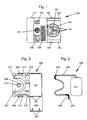
- the miniature pump according to the invention is consisting of three modules, a pump module 100, a tank module 200 and a cassette module 300 which will also be called pump respectively, tank and cassette.
- the reservoir 200 is removably placed in the cassette 300 which, in turn, detachably couples to pump 100.
- the assembled pump has a length of 110 mm, width of 55 mm and thickness of 13 mm for a tank capacity of 10 ml.
- the pump module 100 shown in Figure 1, has a housing in rigid plastic 101, the bottom of which extends to one side to form the base of two parallel slides 102 used to install the cassette module 300 like a drawer. As best seen in Figure 5, each slide 102 is pierced with an opening 103 in which is formed a flexible tongue 104 forming a push button intended to release the cassette when it must be uncoupled from the pump.
- the housing 101 On its upper face, the housing 101 includes a "START / STOP" button 105 used to control the start and stop of the pump, a “BOLUS” button 106 used to trigger the administration of additional doses of solution, an audible warning device 107 and an LCD display 108.
- the housing 101 lets appear, between its two slides 102, a rotor 109 carrying three rollers 110 and forming the pump head. A description detailed will be given later along with that of its means drive.
- the tank module 200 is formed of a pocket in plastic 201 having, in the embodiment shown, a volume of 10 ml and a flexible plastic tube 202, one end of which is connected to the pocket and the other of which, intended to be connected to a subcutaneous injection needle or intravenous, is closed by a plug 203.
- the tube comprises, in addition, in addition, two rigid molded elbow-shaped fittings 204 and 205 for its clipping into the cassette 300, as it will appear better later.
- the cassette module 300 shown seen from below in FIG. 3, is produced rigid plastic and has a housing 301 for receiving the pocket plastic 201. It has substantially the same thickness and the same width as the housing 101 and has, on the bottom side, a cover 302 mounted on two hinges 303 and provided, at the other end, with tabs 304 ensuring its closure by engages.
- the housing 301 is extended by a profiled plate 305 and sized to take place, like a drawer, between the slides 102 of the housing.
- Two tabs 306, arranged on its sides, allow its snap-fastening their end into the openings 103, as well as the also shows figure 5.
- the plate 305 is pierced, on the bottom side, with a housing 307, in the general shape of U, dimensioned so as to receive the rotor 109 of the pump module. he has, for this purpose, a rounded central part 308 of approximately 120 degrees and whose radius is slightly greater than that of the circle traversed by the face outer of the rollers 110. It is on this rounded portion 308 that operation, the three rollers take turns crushing the flexible pipe 202. An additional rounded off clearance 309 is provided around the portion 308 to receive the lower part of the rotor 109, of larger diameter as the circle traversed by the rollers, as it will appear later.
- the bottom of the housing 307 which forms the upper wall of the module, is pierced, in the center of the rounded portion 308, of a circular orifice 310 with regard to the place where the axis of the rotor 109 takes place in order to allow the purging of the pump before use, as will be described later.
- This orifice can be closed by a cover 311 sliding in a recess 312 of the upper wall of the module.
- the plate 305 also includes two channels 313 and 314 each formed in the bottom of one of its sides parallel to this one.
- Channel 313 connects the housing 301 at the front of housing 307. Before opening in it, it has a bent portion 315, of larger diameter, formed and dimensioned so as to receive and hold by clipping the rigid connection 204 of flexible pipe 202.
- Channel 314 starts from the part front of housing 307 opposite to where the other channel arrives and opens out after a bent portion 316, of larger diameter, formed and dimensioned so as to receive and hold by clipping the rigid connection 205 of pipe 202.
- FIGS. 4, 5 and 6 show the way the three previously described modules mate to form the miniature pump according to the invention.
- the tank module 200 is, first of all, placed in the module cassette 300.
- the plastic bag 201 is introduced into its housing 301 and the flexible tube 202 positioned in the channels 313 and 314, taking care that its two rigid connections 204 and 205 take place and snap into place respectively in the bent portions 315 and 316 of the plate 305.
- the end of the game bottom of the rotor 109 occupies the clearance 309 of the plate 305, while the central portion of the flexible tube 202 is automatically trapped between the rotor 109 and the support piece 308.
- the rollers 110 will in turn compress the pipe 102 to push the solution it contains outwards.
- the uncoupling of the pump 100 and cassette modules 300 is achieved by pressing the two buttons 104 so as to release the tongues 306 of the openings 103.
- the cassette can then be extracted by sliding it outwards before removing the tank 200 which can be replaced by another, the cassette and the pump can be reused for a other treatment.
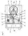
- the pump module 100 will now be described with reference to FIGS. 7 to 11 which show the rotor 109, a stepping motor 111, a gear train 112 coupling the motor to the rotor, an electronic control module 113 and a stick battery 114.
- the rotor 109 shown in detail in Figures 8 and 9, has a base circular 115 provided with peripheral teeth 116 and mounted freely rotation on a pivot 117 forming part of the bottom of the case 101.
- a crown 118 with an outer diameter slightly smaller than that of the base 115, is mounted on the latter and fixed to it by screws 119.
- This crown presents, towards the inside, three flexible arms 120 cut in its mass at 120 ° from each other and forming pawls whose end cooperates with the sawtooth periphery 121 of a wheel 122.
- the peripheral wall of the plate 123 has an inwardly curved profile 124 of so as to form a channel for the passage of the flexible pipe 202.
- This same wall is also pierced with three U-shaped housings 125 arranged at 120 ° from each other to receive the three rollers 110 for compressing the pipe.
- Each roller 110 is formed by an axis 126 and a cylindrical body 127 mounted on the axis around which it can rotate freely. The two ends of this axis take place in oblong openings 128 formed radially in the portions of the plate 123 forming the flat walls lower and upper housings 125. The rollers are held in vertical position, i.e. with their axis parallel to the axis of the rotor, and subject to a radial force directed outwards by two springs 129 arranged on either side of the plate 123.
- Each spring has a central part rigid 130, of substantially triangular shape, fixed to the plate concentrically to it by rivets 131 and three flexible spring arms curved 132 whose free ends bear on the ends respective axes 126 and push them outward so that the rollers 110 exert on the pipe 202 a substantially constant force, fixed at 120 grams in the example described. Positioning errors relative of the rollers and the pipe, due to the inevitable manufacturing defects, are thus automatically compensated, which avoids excessive compression or insufficient hose 202.
- the plate 123 is extended axially upwards by a protuberance 133 passing through the central part 130 of the upper spring 129.
- This protuberance is pierced with the opening of form 134 already mentioned in which can introduce, through the circular opening 310 of the cassette, the profiled tip of corresponding way of a tool (not shown) allowing rotation tray to purge the pump.
- the rotor 109 is driven in rotation by the stepping motor 111 which is of the classic bipolar single-phase type and rotates at the speed of 16 revolutions / second at the rate of two steps per revolution.
- Its core-coil and its stator, respectively designated by the references 135 and 136, are fixed on feet formed in the bottom of the housing 101 by two screws 137.
- Its rotor 138 pivots between the bottom of the case and a bridge 139 fixed by screws 140 on feet secured to the bottom of the case.
- the rotor 138 carries a pinion 141 meshing with a wheel 142 forming the first mobile of the gear train 112.
- the pinion 143 of this wheel itself meshes with a wheel 144 whose pinion 145 finally meshes with the peripheral toothing 116 of the base 115 of the rotor 109 to rotate it the speed of 0.625 rpm.
- the wheels 142 and 144 pivot, as the rotor 138, between the bottom of the case and the bridge 139. The latter ends, after a bend, by two arms 146, not shown in FIG. 9, the end of which common has a circular opening in which is held and pivots the protrusion 133 of the rotor 109.
- the roller-bearing plate When, in order to purge the pipes, the roller-bearing plate is rotated 123 using an appropriately shaped tool inserted into the opening 134, the base 115 and the crown 118 become fixed, because braked by the retention torque of the motor 111 and its gear train 112. A declutching then takes place automatically between the crown 118 and the wheel 122 the fact that the rotation thereof causes the expulsion of the three pawls 120 of sawtooth 121.
- the roller plate 123 can thus be rotated quickly without effect on the gear train and motor.
- the electronic control module 113 shown in FIG. 10, has for base a printed circuit board 147 fixed under the upper face of the housing and carrying the buttons 105 and 106, the horn 107 and the LCD display 108.
- the board also carries a microprocessor circuit 148 integrating the following main functions: voltage doubler, base quartz time, memory, LCD driver and sound generator.
- This microprocessor being of a known type, such as EPSON 62L35, it will not not described in detail. All of these components as well as the battery 114 and the motor coil 111 are interconnected according to the simplified diagram of the figure 11.
- the microprocessor 148 is programmed, according to well known means of the person skilled in the art, so that the assembly works as follows.
- switch 105 When switch 105 is actuated for the first time, it triggers the operation of microprocessor 148 which, under the orders of a program administration stored in memory, applies to motor terminals step by step 111 of the driving pulses at the frequency of 32 Hz causing its rotation at a speed of 16 rpm. The roller rotor 109 is then driven at the speed of 0.625 rpm. Pump operation is interrupted when the switch 105 is actuated a second time.
- the solution advances in the pipe at the speed of 41 mm / min.
- the instantaneous flow rate of the pump is thus 69.54 mm3 / min, i.e. 100 cm3 / day.
- the microprocessor 148 also makes it possible, in response to the actuation of the button 106, to escape the administration program stored in memory for order the injection of a determined additional quantity of solution (Bolus). This procedure is more particularly intended for treatments Pain killer.
- the pump is also provided with means enabling the alarm to be actuated.
- acoustic 107 and / or LCD display 108 in the event of a malfunction: non-compliance with the program, stop, obstruction of the needle, end of life of the pile .... These means are not the subject of this patent, they will not be described.
- FIG. 12 shows an alternative embodiment of the cassette 300 module for treatments requiring the injection of large quantities of solution.
- the cassette can, of course, be extended to receive a larger tank, but if the volume exceeds 20 ml, the size of the pump may make it impractical. For this reason, the cassette module of figure 12 only includes the tray 305 described in FIG. 3, the same references being used to designate the same elements.
- the tank module then includes a large pocket volume 206, which is not inserted in the cassette but only connected to it by a longer flexible tube 202 identical to that described in FIG. 2.
Description
- un rotor équipé d'au moins un galet tournant,
- des moyens d'entraínement dudit rotor,
- des moyens de commande desdits moyens d'entraínement,
- une pièce d'appui munie d'une portion arrondie disposée de manière sensiblement concentrique audit rotor et contre laquelle, en fonctionnement, ledit galet vient comprimer un tuyau souple relié à un réservoir de liquide pour pousser celui-ci vers l'extérieur et
- des moyens pour faire tourner ledit rotor par une action externe afin de réaliser la purge du tuyau.
- en fonctionnement normal, ses deux parties coopèrent pour réaliser sa mise en rotation par ses moyens d'entraínement,
- lorsqu'il est mis en rotation par une action externe, lesdites parties sont automatiquement désaccouplées.
- la figure 1 est vue générale extérieure du module pompe;
- la figure 2 représente le module réservoir;
- la figure 3 représente le module cassette;
- la figure 4 montre la façon dont les trois modules sont accouplés;
- la figure 5 est un détail en coupe de la figure 4 lorsque l'accouplement est réalisé;
- la figure 6 est une vue générale de la pompe assemblée;
- la figure 7 est une vue de dessus du module pompe;
- la figure 8 est une vue en coupe du module pompe selon la ligne VIII-VIII de la figure 7;
- la figure 9 est une vue de dessus du rotor du module pompe;
- la figure 10 montre le module électronique de commande de la pompe;
- la figure 11 est un schéma du circuit de commande de la pompe:
- enfin, la figure 12 illustre une variante de réalisation du module réservoir.
Claims (11)
- Pompe péristaltique portable comportant:ladite pompe étant caractérisée en ce que le rotor est réalisé en deux parties concentriques superposées dont la première est couplée auxdits moyens d'entraínement et dont la deuxième porte ledit galet et en ce qu'il comporte, en outre, des moyens d'embrayage-débrayage grâce auxquels:un rotor (109) équipé d'au moins un galet tournant (110),des moyens d'entraínement (111, 112) dudit rotor,des moyens de commande (113) desdits moyens d'entraínement,une pièce d'appui munie d'une portion arrondie (308) disposée de. manière sensiblement concentrique au rotor et contre laquelle, en fonctionnement, ledit galet vient comprimer un tuyau souple (202) relié à un réservoir de liquide (210) pour pousser celui-ci vers l'extérieur etdes moyens pour faire tourner ledit rotor par une action externe afin de réaliser la purge du tuyau,en fonctionnement normal, ses deux parties coopèrent pour réaliser sa mise en rotation par ses moyens d'entraínement,lorsqu'il est mis en rotation par une action externe, lesdites parties sont automatiquement désaccouplées.
- Pompe péristaltique portable selon la revendication 1, caractérisée en ce que la première partie du rotor comporte une roue dentée (115) coopérant avec lesdits moyens d'entraínement, en ce que sa deuxième partie comporte également une roue dentée (122) formant la base d'un plateau porte-galet (123) et en ce que lesdits moyens d'embrayage-débrayage comportent une couronne (118) fixée sur la roue dentée (115) de la première partie concentriquement à elle, entourant la roue dentée (122) de la deuxième partie et présentant, vers l'intérieur, au moins un bras souple (120) formant cliquet et dont l'extrémité coopère avec la roue dentée de la deuxième partie.
- Pompe péristaltique portable selon l'une des revendications précédentes, caractérisée en ce que les moyens pour faire tourner le rotor par une action externe comportent une protubérance (133) prolongeant l'axe du rotor et percée d'une ouverture de forme (134) destinée à recevoir l'extrémité d'un outil de forme correspondante.
- Pompe péristaltique portable selon l'une des revendications précédentes, caractérisée en ce que:le rotor et son galet, lesdits moyens d'entraínement et lesdits'moyens de commande forment un premier module (100), dit module pompe,la pièce d'appui fait partie d'un deuxième module (300), dit module cassette,lesdits modules sont dotés chacun de moyens permettant leur accouplement etle module cassette comporte des moyens (313, 314) pour recevoir de manière interchangeable ledit tuyau qui fait partie indissociable du réservoir et le positionner automatiquement de manière à ce qu'au moment de l'accouplement des deux modules, il s'applique contre ladite portion arrondie pour y être comprimé par ledit galet, le tuyau et le réservoir formant ainsi un troisième module (200), dit module réservoir, qui peut être aisément échangé avec un autre après usage.
- Pompe péristaltique portable selon la revendication 4, caractérisée en ce que le module cassette comprend un plateau (305) s'engageant, comme un tiroir, dans le module pompe et percé d'un logement (307), en forme générale de U, profilé et dimensionné pour entourer le rotor et dont le fond arrondi (308) constitue la pièce d'appui du tuyau et en ce que les moyens pour recevoir et positionner ledit tuyau comportent un premier (313) et un deuxième (314) canal ménagés le long des côtés respectifs dudit plateau, lesdits canaux ayant une extrémité ouverte sur l'extérieur du plateau et leurs autres extrémités débouchant à l'opposé l'une de l'autre dans l'entrée dudit logement.
- Pompe péristaltique portable selon la revendication 5, caractérisée en ce que lesdits canaux comportent des moyens pour retenir ledit tuyau par enclipsage.
- Pompe péristaltique portable selon la revendication 6, caractérisée en ce que lesdits moyens pour retenir le tuyau sont constitués par des portions coudées (315, 316) desdits canaux, profilées et dimensionnées pour que des portions (204, 205) de forme correspondante dudit tuyau y prennent place et y soient retenues par enclipsage.
- Pompe péristaltique portable selon l'une des revendications 4 à 7, caractérisée en ce que le module cassette se fixe dans le module pompe par enclipsage de son plateau dans des coulisses (102) dudit module pompe.
- Pompe péristaltique portable selon l'une des revendications 4 à 8, caractérisée en ce que le module cassette comprend, en outre, un logement (301) pour recevoir le réservoir de solution.
- Pompe péristaltique portable selon l'une des revendications précédentes, caractérisée en ce que le rotor comporte des moyens de compensation automatique des écarts de position entre le galet et la pièce d'appui.
- Pompe péristaltique portable selon la revendication 10, caractérisée en ce que le galet (110) comporte un corps (127) sensiblement cylindrique et un axe (126) sur lequel ledit corps est monté rotatif, en ce que les extrémités dudit axe prennent place dans des ouvertures oblongues (128) ménagées radialement dans le rotor et en ce que lesdits moyens de compensation comportent deux ressorts (129) disposés au niveau des extrémités respectives de l'axe du galet et comprenant chacun une partie centrale (130) concentrique au rotor et un bras ressort recourbé (132) dont une extrémité est solidaire de ladite partie centrale et dont l'autre extrémité prend place contre l'extrémité correspondante de l'axe du galet pour le pousser radialement vers l'extérieur et permettre ainsi audit galet d'exercer sur le tuyau une force de compression sensiblement constante.
Applications Claiming Priority (3)
| Application Number | Priority Date | Filing Date | Title |
|---|---|---|---|
| FR9611170 | 1996-09-10 | ||
| FR9611170A FR2753235B1 (fr) | 1996-09-10 | 1996-09-10 | Pompe peristaltique portable |
| PCT/CH1997/000327 WO1998011349A1 (fr) | 1996-09-10 | 1997-09-08 | Pompe peristaltique portable |
Publications (2)
| Publication Number | Publication Date |
|---|---|
| EP0927306A1 EP0927306A1 (fr) | 1999-07-07 |
| EP0927306B1 true EP0927306B1 (fr) | 2002-01-23 |
Family
ID=9495705
Family Applications (1)
| Application Number | Title | Priority Date | Filing Date |
|---|---|---|---|
| EP97937395A Expired - Lifetime EP0927306B1 (fr) | 1996-09-10 | 1997-09-08 | Pompe peristaltique portable |
Country Status (6)
| Country | Link |
|---|---|
| US (1) | US6109895A (fr) |
| EP (1) | EP0927306B1 (fr) |
| DE (1) | DE69710082T2 (fr) |
| ES (1) | ES2171987T3 (fr) |
| FR (1) | FR2753235B1 (fr) |
| WO (1) | WO1998011349A1 (fr) |
Families Citing this family (84)
| Publication number | Priority date | Publication date | Assignee | Title |
|---|---|---|---|---|
| DE19916876A1 (de) * | 1999-04-14 | 2000-11-02 | Clemens Micheler | Medizinische Dosierpumpe |
| US6497676B1 (en) | 2000-02-10 | 2002-12-24 | Baxter International | Method and apparatus for monitoring and controlling peritoneal dialysis therapy |
| EP1229244A1 (fr) | 2001-01-31 | 2002-08-07 | Precimedix S.A. | Detecteur d'obstruction pour pompe peristaltique rotative |
| JP4557452B2 (ja) * | 2001-03-13 | 2010-10-06 | 日本電産サーボ株式会社 | ローラポンプ |
| EP1249606A1 (fr) | 2001-04-10 | 2002-10-16 | Precimedix S.A. | Pompe à cassette programmable pour l'injection de médicaments |
| US20030125662A1 (en) | 2002-01-03 | 2003-07-03 | Tuan Bui | Method and apparatus for providing medical treatment therapy based on calculated demand |
| US7666213B2 (en) | 2002-07-11 | 2010-02-23 | Life Recovery Systems Hd, Llc | Apparatus for altering the body temperature of a patient |
| US7238164B2 (en) | 2002-07-19 | 2007-07-03 | Baxter International Inc. | Systems, methods and apparatuses for pumping cassette-based therapies |
| EP1384490A1 (fr) | 2002-07-22 | 2004-01-28 | Precimedix S.A. | Pompe programmable pour l'injection de médicaments |
| EP1389476A1 (fr) * | 2002-08-14 | 2004-02-18 | Precimedix S.A. | Dispositif de programmation d'une pompe pour l'injection de medicaments |
| DE10244090A1 (de) * | 2002-09-23 | 2004-04-01 | Ismatec S.A. | Schlauchkassette für eine peristaltische Pumpe |
| US7238010B2 (en) * | 2003-04-14 | 2007-07-03 | Stryker Corporation | Surgical irrigation pump and tool system |
| US7168930B2 (en) * | 2003-09-29 | 2007-01-30 | Bausch & Lomb Incorporated | Peristaltic pump with air venting via the movement of a pump head or a backing plate during surgery |
| US7445436B2 (en) * | 2003-09-29 | 2008-11-04 | Bausch & Lomb Incorporated | Peristaltic pump with a moveable pump head |
| CA2579041A1 (fr) * | 2004-09-07 | 2006-03-16 | Smith & Nephew, Inc. | Procedes et dispositifs pour transfert de champ sterile |
| US7377935B2 (en) | 2004-09-24 | 2008-05-27 | Life Recovery Systems Hd, Llc | Apparatus for altering the body temperature of a patient |
| WO2006058153A1 (fr) | 2004-11-23 | 2006-06-01 | Smith & Nephew, Inc. | Melangeur composite |
| US8303542B2 (en) * | 2006-06-10 | 2012-11-06 | Bausch & Lomb Incorporated | Ophthalmic surgical cassette and system |
| EP2068789A4 (fr) * | 2006-08-24 | 2012-10-31 | Life Recovery Systems Hd Llc | Dispositif pour modifier la température corporelle d'un patient |
| US7771461B2 (en) * | 2006-08-24 | 2010-08-10 | Life Recovery Systems Hd, Llc | Apparatus for altering the body temperature of a patient |
| US8491528B2 (en) | 2006-11-09 | 2013-07-23 | Abbott Medical Optics Inc. | Critical alignment of fluidics cassettes |
| US9522221B2 (en) | 2006-11-09 | 2016-12-20 | Abbott Medical Optics Inc. | Fluidics cassette for ocular surgical system |
| US8414534B2 (en) | 2006-11-09 | 2013-04-09 | Abbott Medical Optics Inc. | Holding tank devices, systems, and methods for surgical fluidics cassette |
| US9295765B2 (en) | 2006-11-09 | 2016-03-29 | Abbott Medical Optics Inc. | Surgical fluidics cassette supporting multiple pumps |
| US10959881B2 (en) | 2006-11-09 | 2021-03-30 | Johnson & Johnson Surgical Vision, Inc. | Fluidics cassette for ocular surgical system |
| WO2008070849A2 (fr) * | 2006-12-07 | 2008-06-12 | Life Recovery Systems Hd, Llc | Appareil pour modifier la température corporelle d'un patient |
| US8361023B2 (en) | 2007-02-15 | 2013-01-29 | Baxter International Inc. | Dialysis system with efficient battery back-up |
| US8870812B2 (en) | 2007-02-15 | 2014-10-28 | Baxter International Inc. | Dialysis system having video display with ambient light adjustment |
| US7998115B2 (en) * | 2007-02-15 | 2011-08-16 | Baxter International Inc. | Dialysis system having optical flowrate detection |
| US7731689B2 (en) | 2007-02-15 | 2010-06-08 | Baxter International Inc. | Dialysis system having inductive heating |
| US8558964B2 (en) | 2007-02-15 | 2013-10-15 | Baxter International Inc. | Dialysis system having display with electromagnetic compliance (“EMC”) seal |
| US10596032B2 (en) | 2007-05-24 | 2020-03-24 | Johnson & Johnson Surgical Vision, Inc. | System and method for controlling a transverse phacoemulsification system with a footpedal |
| US10363166B2 (en) | 2007-05-24 | 2019-07-30 | Johnson & Johnson Surgical Vision, Inc. | System and method for controlling a transverse phacoemulsification system using sensed data |
| US10485699B2 (en) | 2007-05-24 | 2019-11-26 | Johnson & Johnson Surgical Vision, Inc. | Systems and methods for transverse phacoemulsification |
| US10342701B2 (en) | 2007-08-13 | 2019-07-09 | Johnson & Johnson Surgical Vision, Inc. | Systems and methods for phacoemulsification with vacuum based pumps |
| US8083503B2 (en) | 2007-09-27 | 2011-12-27 | Curlin Medical Inc. | Peristaltic pump assembly and regulator therefor |
| US8062008B2 (en) | 2007-09-27 | 2011-11-22 | Curlin Medical Inc. | Peristaltic pump and removable cassette therefor |
| US7934912B2 (en) | 2007-09-27 | 2011-05-03 | Curlin Medical Inc | Peristaltic pump assembly with cassette and mounting pin arrangement |
| EP2140890A1 (fr) * | 2008-07-03 | 2010-01-06 | Bien-Air Holding SA | Pompe péristaltique et ligne d'irrigation |
| CA2733825C (fr) | 2008-11-07 | 2017-09-12 | Abbott Medical Optics Inc. | Procede de programmation des reglages d'une pedale et de controle des performances obtenues par actionnement de la pedale |
| AU2009313384B2 (en) | 2008-11-07 | 2015-06-11 | Johnson & Johnson Surgical Vision, Inc. | Automatically pulsing different aspiration levels to an ocular probe |
| EP3156012B1 (fr) | 2008-11-07 | 2021-10-20 | Johnson & Johnson Surgical Vision, Inc. | Pédale de commande réglable pour chirurgie ophtalmique |
| CA2941772C (fr) | 2008-11-07 | 2018-10-23 | Abbott Medical Optics Inc. | Changement automatique entre differents niveaux d'aspiration appliques a une sonde oculaire et/ou differentes pompes utilisees avec cette derniere |
| CA2742978C (fr) | 2008-11-07 | 2017-08-15 | Abbott Medical Optics Inc. | Controle de plusieurs pompes |
| AU2009313416B2 (en) | 2008-11-07 | 2015-03-26 | Johnson & Johnson Surgical Vision, Inc. | Surgical cassette apparatus |
| US9795507B2 (en) | 2008-11-07 | 2017-10-24 | Abbott Medical Optics Inc. | Multifunction foot pedal |
| CA2743053C (fr) * | 2008-11-10 | 2016-07-19 | Curlin Medical Inc. | Procede et appareil pour pompe peristaltique |
| US9492317B2 (en) | 2009-03-31 | 2016-11-15 | Abbott Medical Optics Inc. | Cassette capture mechanism |
| AU2010245166B2 (en) | 2009-05-06 | 2014-04-17 | Alcon Inc. | Multiple segmented peristaltic pump and cassette |
| EP2462346B1 (fr) | 2009-07-14 | 2015-09-30 | Sanofi-Aventis Deutschland GmbH | Agencement d'injection |
| US20110137231A1 (en) | 2009-12-08 | 2011-06-09 | Alcon Research, Ltd. | Phacoemulsification Hand Piece With Integrated Aspiration Pump |
| WO2012094641A2 (fr) | 2011-01-06 | 2012-07-12 | Thoratec Corporation | Pompe cardiaque percutanée |
| ITVR20120034A1 (it) * | 2012-03-02 | 2013-09-03 | Tecres Spa | Dispositivo infusore universale per liquidi medicinali e simili, e metodo per il controllo dell'erogazione di liquido medicinale e simili. |
| CA2875074A1 (fr) | 2012-03-17 | 2013-09-26 | Abbott Medical Optics Inc. | Cassette chirurgicale |
| US8721517B2 (en) | 2012-05-14 | 2014-05-13 | Thoratec Corporation | Impeller for catheter pump |
| GB2504176A (en) | 2012-05-14 | 2014-01-22 | Thoratec Corp | Collapsible impeller for catheter pump |
| US9358329B2 (en) | 2012-07-03 | 2016-06-07 | Thoratec Corporation | Catheter pump |
| US9445943B2 (en) | 2012-12-11 | 2016-09-20 | Alcon Research, Ltd. | Phacoemulsification hand piece with integrated aspiration and irrigation pump |
| US9962288B2 (en) | 2013-03-07 | 2018-05-08 | Novartis Ag | Active acoustic streaming in hand piece for occlusion surge mitigation |
| US11033728B2 (en) | 2013-03-13 | 2021-06-15 | Tc1 Llc | Fluid handling system |
| EP2968718B1 (fr) | 2013-03-13 | 2021-04-21 | Tc1 Llc | Système de traitement de fluide |
| USD746975S1 (en) | 2013-03-14 | 2016-01-05 | Thoratec Corporation | Catheter pump console |
| WO2014143593A1 (fr) | 2013-03-15 | 2014-09-18 | Thoratec Corporation | Ensemble pompe de cathéter comprenant un stator |
| US9545337B2 (en) | 2013-03-15 | 2017-01-17 | Novartis Ag | Acoustic streaming glaucoma drainage device |
| US9126219B2 (en) | 2013-03-15 | 2015-09-08 | Alcon Research, Ltd. | Acoustic streaming fluid ejector |
| US9915274B2 (en) | 2013-03-15 | 2018-03-13 | Novartis Ag | Acoustic pumps and systems |
| US9693896B2 (en) | 2013-03-15 | 2017-07-04 | Novartis Ag | Systems and methods for ocular surgery |
| US9308302B2 (en) | 2013-03-15 | 2016-04-12 | Thoratec Corporation | Catheter pump assembly including a stator |
| US9750638B2 (en) | 2013-03-15 | 2017-09-05 | Novartis Ag | Systems and methods for ocular surgery |
| AU2014317795B2 (en) * | 2013-09-03 | 2019-05-30 | Jacqueline Sarah SAVAGE | Wearable intravenous fluid delivery system |
| WO2015160943A1 (fr) | 2014-04-15 | 2015-10-22 | Thoratec Corporation | Capteurs pour pompes de cathéter |
| US10449279B2 (en) | 2014-08-18 | 2019-10-22 | Tc1 Llc | Guide features for percutaneous catheter pump |
| USD770034S1 (en) | 2015-01-09 | 2016-10-25 | BioQ Pharma, Inc. | Liquid medicament dosage control and delivery device |
| US9987416B2 (en) | 2015-01-09 | 2018-06-05 | BioQuiddity Inc. | Sterile assembled liquid medicament dosage control and delivery device |
| WO2016118777A1 (fr) | 2015-01-22 | 2016-07-28 | Thoratec Corporation | Ensemble moteur à masse de rotation réduite pour pompe pour cathéter |
| US9775946B2 (en) | 2016-02-11 | 2017-10-03 | Bioq Pharma Inc. | Unified drug mixer and dispenser |
| CN106139299A (zh) * | 2016-06-28 | 2016-11-23 | 范永建 | 一种便携式静脉输液器 |
| EP3808401A1 (fr) | 2016-07-21 | 2021-04-21 | Tc1 Llc | Chambre remplie de gaz pour ensemble moteur de pompe de cathéter |
| US11160970B2 (en) | 2016-07-21 | 2021-11-02 | Tc1 Llc | Fluid seals for catheter pump motor assembly |
| US11179516B2 (en) | 2017-06-22 | 2021-11-23 | Baxter International Inc. | Systems and methods for incorporating patient pressure into medical fluid delivery |
| DE102018104807B4 (de) * | 2018-03-02 | 2020-10-29 | Krömker Holding GmbH | Punktionsabsaugeinrichtung |
| US10994116B2 (en) | 2018-06-30 | 2021-05-04 | Bioq Pharma Incorporated | Drug cartridge-based infusion pump |
| US11338082B2 (en) | 2019-09-04 | 2022-05-24 | BloQ Pharma, Inc. | Variable rate dispenser with aseptic spike connector assembly |
| DE102020206875A1 (de) | 2020-06-03 | 2021-12-09 | B.Braun Avitum Ag | Peristaltikpumpe für eine Vorrichtung zur extrakorporalen Blutbehandlung |
Family Cites Families (19)
| Publication number | Priority date | Publication date | Assignee | Title |
|---|---|---|---|---|
| US3700361A (en) * | 1971-07-08 | 1972-10-24 | Sarns Inc | Peristaltic pump construction |
| US3816035A (en) * | 1972-10-24 | 1974-06-11 | E Malbec | Peristaltic pump |
| US3960466A (en) * | 1975-02-10 | 1976-06-01 | Taylor Edward J | Douche-enema pump |
| US4083777A (en) * | 1976-09-07 | 1978-04-11 | Union Carbide Corporation | Portable hemodialysis system |
| US4210138A (en) * | 1977-12-02 | 1980-07-01 | Baxter Travenol Laboratories, Inc. | Metering apparatus for a fluid infusion system with flow control station |
| US4229299A (en) * | 1978-03-22 | 1980-10-21 | Hoechst Aktiengesellschaft | Peristaltic dialysate solution pump |
| JPS5870079A (ja) * | 1981-10-23 | 1983-04-26 | Pilot Pen Co Ltd:The | ぜん動ポンプ |
| US4487558A (en) * | 1982-08-23 | 1984-12-11 | Extracorporeal Medical Specialties, Inc. | Peristaltic pump |
| US4558996A (en) * | 1983-06-30 | 1985-12-17 | Organon Teknika Corporation | Easy load peristaltic pump |
| US4599055A (en) * | 1985-06-25 | 1986-07-08 | Cobe Laboratories, Inc. | Peristaltic pump |
| US4705464A (en) * | 1986-05-09 | 1987-11-10 | Surgidev Corporation | Medicine pump |
| FR2644853B1 (fr) * | 1989-03-24 | 1994-03-04 | Asulab Sa | Pompe peristaltique miniature |
| FR2659856B1 (fr) * | 1990-03-23 | 1992-06-05 | Asulab Sa | Pompe portable d'administration d'une substance therapeutique liquide. |
| DE4037797C1 (en) * | 1990-11-28 | 1992-02-13 | Fresenius Ag, 6380 Bad Homburg, De | Peristaltic pump for fluid - has stator braced in direction of rotor and adjustable by eccentric disc |
| US5250027A (en) * | 1991-10-08 | 1993-10-05 | Sherwood Medical Company | Peristaltic infusion device with backpack sensor |
| ATE123655T1 (de) * | 1991-07-05 | 1995-06-15 | Asulab Sa | Tragbare pumpe zur verarbeitung therapeutischer flüssigkeiten. |
| FR2708675B1 (fr) * | 1993-08-06 | 1995-10-20 | Debiotech | Cassette de pompe péristaltique. |
| US5460493A (en) * | 1993-11-17 | 1995-10-24 | Baxter International Inc. | Organizer frame for holding an array of flexible tubing in alignment with one or more peristaltic pump rotors |
| US5752813A (en) * | 1996-10-23 | 1998-05-19 | A.Z.E. Medical Inc. | Keyed cassette for dispensing pump |
-
1996
- 1996-09-10 FR FR9611170A patent/FR2753235B1/fr not_active Expired - Fee Related
-
1997
- 1997-09-08 ES ES97937395T patent/ES2171987T3/es not_active Expired - Lifetime
- 1997-09-08 EP EP97937395A patent/EP0927306B1/fr not_active Expired - Lifetime
- 1997-09-08 US US09/254,581 patent/US6109895A/en not_active Expired - Fee Related
- 1997-09-08 DE DE69710082T patent/DE69710082T2/de not_active Expired - Fee Related
- 1997-09-08 WO PCT/CH1997/000327 patent/WO1998011349A1/fr active IP Right Grant
Also Published As
| Publication number | Publication date |
|---|---|
| FR2753235A1 (fr) | 1998-03-13 |
| ES2171987T3 (es) | 2002-09-16 |
| US6109895A (en) | 2000-08-29 |
| FR2753235B1 (fr) | 1998-12-04 |
| WO1998011349A1 (fr) | 1998-03-19 |
| DE69710082D1 (de) | 2002-03-14 |
| DE69710082T2 (de) | 2002-09-26 |
| EP0927306A1 (fr) | 1999-07-07 |
Similar Documents
| Publication | Publication Date | Title |
|---|---|---|
| EP0927306B1 (fr) | Pompe peristaltique portable | |
| EP0927307B1 (fr) | Pompe peristaltique miniature | |
| EP0523354B1 (fr) | Pompe péristaltique | |
| EP0447909B1 (fr) | Pompe portable d'administration d'une substance thérapeutique liquide | |
| EP0851774A1 (fr) | Piston de seringue avec transmission lineaire | |
| WO1999021597A1 (fr) | Dispositif d'administration de substances therapeutiques a seringue motorisee | |
| WO2002061281A1 (fr) | Detecteur d"obstruction pour pompe peristaltique rotative | |
| EP3897938B1 (fr) | Machine a mélange pour la fabrication d'une composition a partir d'un mélange de formulations | |
| EP0932423B1 (fr) | Pompe peristaltique miniature a usage medical | |
| EP0026704A1 (fr) | Pompe péristaltique | |
| FR2872554A1 (fr) | Pompe peristaltique comportant des organes de mise en position d'un tube | |
| EP3897944B1 (fr) | Appareil de fabrication et machine à mélange pour la fabrication d'une composition à partir d'un mélange de formulations | |
| EP3897937A1 (fr) | Appareil de fabrication pour la fabrication d'une composition a partir d'un mélange de formulations | |
| EP0521184A1 (fr) | Pompe portable d'administration d'une substance thérapeutique liquide | |
| FR2826871A1 (fr) | Unite a aiguille d'injection pour appareil automatique et portable a seringue | |
| EP3897943B1 (fr) | Appareil de fabrication pour la fabrication d'une composition a partir d'un mélange de formulations | |
| EP3897935B1 (fr) | Appareil de fabrication pour la fabrication d'une composition a partir d'un mélange de formulations | |
| EP3897936B1 (fr) | Appareil de fabrication pour la fabrication d'une composition a partir d'un mélange de formulations | |
| WO2020127910A1 (fr) | Appareil de fabrication et dispositif de réception pour la fabrication d'une composition a partir d'un mélange de formulations | |
| FR2786105A1 (fr) | Dispositif d'administration de medicament liquide pour une injection dans un vaisseau sanguin | |
| FR3031450A1 (fr) | Tete de massage et appareil de massage mettant en œuvre une telle tete | |
| WO2000015280A1 (fr) | Dispositifs d'administration de substances therapeutiques a seringue motorisee | |
| EP4065193A1 (fr) | Dispositif d'injection d'un produit | |
| FR3110642A1 (fr) | Pompe | |
| FR2719765A1 (fr) | Dispositif de dégazage et de contrôle de la pression interne d'une poche de recueil pour stomie. |
Legal Events
| Date | Code | Title | Description |
|---|---|---|---|
| PUAI | Public reference made under article 153(3) epc to a published international application that has entered the european phase |
Free format text: ORIGINAL CODE: 0009012 |
|
| 17P | Request for examination filed |
Effective date: 19990401 |
|
| AK | Designated contracting states |
Kind code of ref document: A1 Designated state(s): BE CH DE DK ES GB IT LI NL PT SE |
|
| GRAG | Despatch of communication of intention to grant |
Free format text: ORIGINAL CODE: EPIDOS AGRA |
|
| GRAG | Despatch of communication of intention to grant |
Free format text: ORIGINAL CODE: EPIDOS AGRA |
|
| GRAH | Despatch of communication of intention to grant a patent |
Free format text: ORIGINAL CODE: EPIDOS IGRA |
|
| 17Q | First examination report despatched |
Effective date: 20010606 |
|
| GRAH | Despatch of communication of intention to grant a patent |
Free format text: ORIGINAL CODE: EPIDOS IGRA |
|
| GRAA | (expected) grant |
Free format text: ORIGINAL CODE: 0009210 |
|
| REG | Reference to a national code |
Ref country code: GB Ref legal event code: IF02 |
|
| RAP1 | Party data changed (applicant data changed or rights of an application transferred) |
Owner name: PRECIMEDIX S.A. |
|
| AK | Designated contracting states |
Kind code of ref document: B1 Designated state(s): BE CH DE DK ES GB IT LI NL PT SE |
|
| REG | Reference to a national code |
Ref country code: CH Ref legal event code: EP |
|
| REF | Corresponds to: |
Ref document number: 69710082 Country of ref document: DE Date of ref document: 20020314 |
|
| REG | Reference to a national code |
Ref country code: CH Ref legal event code: NV Representative=s name: GRESSET - LAESSER CABINET DE CONSEILS EN PROPRIETE |
|
| PG25 | Lapsed in a contracting state [announced via postgrant information from national office to epo] |
Ref country code: SE Free format text: LAPSE BECAUSE OF FAILURE TO SUBMIT A TRANSLATION OF THE DESCRIPTION OR TO PAY THE FEE WITHIN THE PRESCRIBED TIME-LIMIT Effective date: 20020423 Ref country code: PT Free format text: LAPSE BECAUSE OF FAILURE TO SUBMIT A TRANSLATION OF THE DESCRIPTION OR TO PAY THE FEE WITHIN THE PRESCRIBED TIME-LIMIT Effective date: 20020423 Ref country code: DK Free format text: LAPSE BECAUSE OF FAILURE TO SUBMIT A TRANSLATION OF THE DESCRIPTION OR TO PAY THE FEE WITHIN THE PRESCRIBED TIME-LIMIT Effective date: 20020423 |
|
| GBT | Gb: translation of ep patent filed (gb section 77(6)(a)/1977) |
Effective date: 20020409 |
|
| REG | Reference to a national code |
Ref country code: ES Ref legal event code: FG2A Ref document number: 2171987 Country of ref document: ES Kind code of ref document: T3 |
|
| PLBE | No opposition filed within time limit |
Free format text: ORIGINAL CODE: 0009261 |
|
| STAA | Information on the status of an ep patent application or granted ep patent |
Free format text: STATUS: NO OPPOSITION FILED WITHIN TIME LIMIT |
|
| 26N | No opposition filed | ||
| PGFP | Annual fee paid to national office [announced via postgrant information from national office to epo] |
Ref country code: BE Payment date: 20030908 Year of fee payment: 7 |
|
| PGFP | Annual fee paid to national office [announced via postgrant information from national office to epo] |
Ref country code: ES Payment date: 20030911 Year of fee payment: 7 |
|
| PGFP | Annual fee paid to national office [announced via postgrant information from national office to epo] |
Ref country code: NL Payment date: 20030924 Year of fee payment: 7 |
|
| PG25 | Lapsed in a contracting state [announced via postgrant information from national office to epo] |
Ref country code: ES Free format text: LAPSE BECAUSE OF NON-PAYMENT OF DUE FEES Effective date: 20040909 |
|
| PG25 | Lapsed in a contracting state [announced via postgrant information from national office to epo] |
Ref country code: BE Free format text: LAPSE BECAUSE OF NON-PAYMENT OF DUE FEES Effective date: 20040930 |
|
| BERE | Be: lapsed |
Owner name: S.A. *PRECIMEDIX Effective date: 20040930 |
|
| PG25 | Lapsed in a contracting state [announced via postgrant information from national office to epo] |
Ref country code: NL Free format text: LAPSE BECAUSE OF NON-PAYMENT OF DUE FEES Effective date: 20050401 |
|
| NLV4 | Nl: lapsed or anulled due to non-payment of the annual fee |
Effective date: 20050401 |
|
| PG25 | Lapsed in a contracting state [announced via postgrant information from national office to epo] |
Ref country code: IT Free format text: LAPSE BECAUSE OF NON-PAYMENT OF DUE FEES Effective date: 20050908 |
|
| REG | Reference to a national code |
Ref country code: ES Ref legal event code: FD2A Effective date: 20040909 |
|
| PGFP | Annual fee paid to national office [announced via postgrant information from national office to epo] |
Ref country code: GB Payment date: 20060925 Year of fee payment: 10 |
|
| PGFP | Annual fee paid to national office [announced via postgrant information from national office to epo] |
Ref country code: CH Payment date: 20060928 Year of fee payment: 10 |
|
| PGFP | Annual fee paid to national office [announced via postgrant information from national office to epo] |
Ref country code: DE Payment date: 20061031 Year of fee payment: 10 |
|
| BERE | Be: lapsed |
Owner name: S.A. *PRECIMEDIX Effective date: 20040930 |
|
| REG | Reference to a national code |
Ref country code: CH Ref legal event code: PL |
|
| GBPC | Gb: european patent ceased through non-payment of renewal fee |
Effective date: 20070908 |
|
| PG25 | Lapsed in a contracting state [announced via postgrant information from national office to epo] |
Ref country code: LI Free format text: LAPSE BECAUSE OF NON-PAYMENT OF DUE FEES Effective date: 20070930 Ref country code: DE Free format text: LAPSE BECAUSE OF NON-PAYMENT OF DUE FEES Effective date: 20080401 Ref country code: CH Free format text: LAPSE BECAUSE OF NON-PAYMENT OF DUE FEES Effective date: 20070930 |
|
| PG25 | Lapsed in a contracting state [announced via postgrant information from national office to epo] |
Ref country code: GB Free format text: LAPSE BECAUSE OF NON-PAYMENT OF DUE FEES Effective date: 20070908 |