EP0926576B1 - Nichtlineare modellgestützte prädiktive Regelungsmethode zur Regelung eines Gasphasenreaktors. - Google Patents
Nichtlineare modellgestützte prädiktive Regelungsmethode zur Regelung eines Gasphasenreaktors. Download PDFInfo
- Publication number
- EP0926576B1 EP0926576B1 EP98124146A EP98124146A EP0926576B1 EP 0926576 B1 EP0926576 B1 EP 0926576B1 EP 98124146 A EP98124146 A EP 98124146A EP 98124146 A EP98124146 A EP 98124146A EP 0926576 B1 EP0926576 B1 EP 0926576B1
- Authority
- EP
- European Patent Office
- Prior art keywords
- sign
- chemical reactor
- controller
- signals
- reactor
- Prior art date
- Legal status (The legal status is an assumption and is not a legal conclusion. Google has not performed a legal analysis and makes no representation as to the accuracy of the status listed.)
- Expired - Lifetime
Links
- 238000000034 method Methods 0.000 title claims abstract description 138
- 239000000126 substance Substances 0.000 claims abstract description 36
- 230000009021 linear effect Effects 0.000 claims abstract description 12
- 238000001914 filtration Methods 0.000 claims abstract description 9
- 239000000376 reactant Substances 0.000 claims abstract description 9
- 239000000470 constituent Substances 0.000 claims abstract description 4
- 230000008859 change Effects 0.000 claims description 44
- 230000014509 gene expression Effects 0.000 claims description 13
- 238000004422 calculation algorithm Methods 0.000 claims description 12
- 230000004044 response Effects 0.000 description 47
- 239000007789 gas Substances 0.000 description 32
- VGGSQFUCUMXWEO-UHFFFAOYSA-N Ethene Chemical compound C=C VGGSQFUCUMXWEO-UHFFFAOYSA-N 0.000 description 23
- 239000005977 Ethylene Substances 0.000 description 23
- 230000008569 process Effects 0.000 description 22
- 239000000047 product Substances 0.000 description 22
- 239000007788 liquid Substances 0.000 description 20
- 238000004886 process control Methods 0.000 description 19
- 238000004364 calculation method Methods 0.000 description 16
- 238000012360 testing method Methods 0.000 description 15
- 238000010586 diagram Methods 0.000 description 13
- 230000007704 transition Effects 0.000 description 13
- 239000000203 mixture Substances 0.000 description 11
- 239000000178 monomer Substances 0.000 description 11
- QQONPFPTGQHPMA-UHFFFAOYSA-N propylene Natural products CC=C QQONPFPTGQHPMA-UHFFFAOYSA-N 0.000 description 11
- 125000004805 propylene group Chemical group [H]C([H])([H])C([H])([*:1])C([H])([H])[*:2] 0.000 description 11
- UFHFLCQGNIYNRP-UHFFFAOYSA-N Hydrogen Chemical compound [H][H] UFHFLCQGNIYNRP-UHFFFAOYSA-N 0.000 description 10
- 230000008878 coupling Effects 0.000 description 10
- 238000010168 coupling process Methods 0.000 description 10
- 238000005859 coupling reaction Methods 0.000 description 10
- 239000001257 hydrogen Substances 0.000 description 10
- 229910052739 hydrogen Inorganic materials 0.000 description 10
- 238000004519 manufacturing process Methods 0.000 description 10
- 230000008901 benefit Effects 0.000 description 9
- 230000006870 function Effects 0.000 description 9
- 238000009499 grossing Methods 0.000 description 9
- 230000001276 controlling effect Effects 0.000 description 8
- 230000000694 effects Effects 0.000 description 8
- 230000009471 action Effects 0.000 description 7
- 230000003044 adaptive effect Effects 0.000 description 7
- 230000006872 improvement Effects 0.000 description 7
- 238000005259 measurement Methods 0.000 description 7
- 239000012530 fluid Substances 0.000 description 6
- 229920000642 polymer Polymers 0.000 description 6
- 238000011161 development Methods 0.000 description 5
- 229920001519 homopolymer Polymers 0.000 description 5
- 230000003993 interaction Effects 0.000 description 5
- 230000001052 transient effect Effects 0.000 description 5
- 230000001934 delay Effects 0.000 description 4
- 238000013461 design Methods 0.000 description 4
- 230000000368 destabilizing effect Effects 0.000 description 4
- 239000012467 final product Substances 0.000 description 4
- 238000007689 inspection Methods 0.000 description 4
- 238000011217 control strategy Methods 0.000 description 3
- 239000004615 ingredient Substances 0.000 description 3
- 239000011159 matrix material Substances 0.000 description 3
- -1 pressure Substances 0.000 description 3
- 230000000087 stabilizing effect Effects 0.000 description 3
- 101000998140 Homo sapiens Interleukin-36 alpha Proteins 0.000 description 2
- 101000998126 Homo sapiens Interleukin-36 beta Proteins 0.000 description 2
- 101001040964 Homo sapiens Interleukin-36 receptor antagonist protein Proteins 0.000 description 2
- 101000998122 Homo sapiens Interleukin-37 Proteins 0.000 description 2
- 102100021150 Interleukin-36 receptor antagonist protein Human genes 0.000 description 2
- 101100375588 Oryza sativa subsp. japonica YAB2 gene Proteins 0.000 description 2
- ATUOYWHBWRKTHZ-UHFFFAOYSA-N Propane Chemical compound CCC ATUOYWHBWRKTHZ-UHFFFAOYSA-N 0.000 description 2
- 238000013459 approach Methods 0.000 description 2
- 239000003054 catalyst Substances 0.000 description 2
- 238000001311 chemical methods and process Methods 0.000 description 2
- 230000003247 decreasing effect Effects 0.000 description 2
- 230000003111 delayed effect Effects 0.000 description 2
- 238000005516 engineering process Methods 0.000 description 2
- 238000005243 fluidization Methods 0.000 description 2
- 238000013178 mathematical model Methods 0.000 description 2
- 230000008450 motivation Effects 0.000 description 2
- 230000010355 oscillation Effects 0.000 description 2
- 238000005070 sampling Methods 0.000 description 2
- 230000001629 suppression Effects 0.000 description 2
- 238000012549 training Methods 0.000 description 2
- 238000012546 transfer Methods 0.000 description 2
- 108010014172 Factor V Proteins 0.000 description 1
- 238000004566 IR spectroscopy Methods 0.000 description 1
- CTQNGGLPUBDAKN-UHFFFAOYSA-N O-Xylene Chemical compound CC1=CC=CC=C1C CTQNGGLPUBDAKN-UHFFFAOYSA-N 0.000 description 1
- 150000001336 alkenes Chemical class 0.000 description 1
- 238000004458 analytical method Methods 0.000 description 1
- 238000006243 chemical reaction Methods 0.000 description 1
- 239000007795 chemical reaction product Substances 0.000 description 1
- 238000010960 commercial process Methods 0.000 description 1
- 238000005094 computer simulation Methods 0.000 description 1
- 238000012937 correction Methods 0.000 description 1
- 230000002089 crippling effect Effects 0.000 description 1
- 230000007812 deficiency Effects 0.000 description 1
- 230000001419 dependent effect Effects 0.000 description 1
- 238000001514 detection method Methods 0.000 description 1
- 230000008030 elimination Effects 0.000 description 1
- 238000003379 elimination reaction Methods 0.000 description 1
- 238000011156 evaluation Methods 0.000 description 1
- 238000009472 formulation Methods 0.000 description 1
- 230000005484 gravity Effects 0.000 description 1
- 238000010348 incorporation Methods 0.000 description 1
- 238000011835 investigation Methods 0.000 description 1
- 238000012886 linear function Methods 0.000 description 1
- 239000000463 material Substances 0.000 description 1
- 238000013508 migration Methods 0.000 description 1
- 230000005012 migration Effects 0.000 description 1
- 238000012821 model calculation Methods 0.000 description 1
- 238000012986 modification Methods 0.000 description 1
- 230000004048 modification Effects 0.000 description 1
- 230000009022 nonlinear effect Effects 0.000 description 1
- JRZJOMJEPLMPRA-UHFFFAOYSA-N olefin Natural products CCCCCCCC=C JRZJOMJEPLMPRA-UHFFFAOYSA-N 0.000 description 1
- 238000005457 optimization Methods 0.000 description 1
- 230000002085 persistent effect Effects 0.000 description 1
- 238000006116 polymerization reaction Methods 0.000 description 1
- 238000004540 process dynamic Methods 0.000 description 1
- 230000000750 progressive effect Effects 0.000 description 1
- 239000001294 propane Substances 0.000 description 1
- 230000001105 regulatory effect Effects 0.000 description 1
- 238000011160 research Methods 0.000 description 1
- 230000035945 sensitivity Effects 0.000 description 1
- 230000006641 stabilisation Effects 0.000 description 1
- 238000011105 stabilization Methods 0.000 description 1
- 230000002459 sustained effect Effects 0.000 description 1
- 238000011144 upstream manufacturing Methods 0.000 description 1
- 239000008096 xylene Substances 0.000 description 1
Images













Classifications
-
- G—PHYSICS
- G05—CONTROLLING; REGULATING
- G05B—CONTROL OR REGULATING SYSTEMS IN GENERAL; FUNCTIONAL ELEMENTS OF SUCH SYSTEMS; MONITORING OR TESTING ARRANGEMENTS FOR SUCH SYSTEMS OR ELEMENTS
- G05B13/00—Adaptive control systems, i.e. systems automatically adjusting themselves to have a performance which is optimum according to some preassigned criterion
- G05B13/02—Adaptive control systems, i.e. systems automatically adjusting themselves to have a performance which is optimum according to some preassigned criterion electric
- G05B13/04—Adaptive control systems, i.e. systems automatically adjusting themselves to have a performance which is optimum according to some preassigned criterion electric involving the use of models or simulators
- G05B13/048—Adaptive control systems, i.e. systems automatically adjusting themselves to have a performance which is optimum according to some preassigned criterion electric involving the use of models or simulators using a predictor
-
- C—CHEMISTRY; METALLURGY
- C08—ORGANIC MACROMOLECULAR COMPOUNDS; THEIR PREPARATION OR CHEMICAL WORKING-UP; COMPOSITIONS BASED THEREON
- C08F—MACROMOLECULAR COMPOUNDS OBTAINED BY REACTIONS ONLY INVOLVING CARBON-TO-CARBON UNSATURATED BONDS
- C08F10/00—Homopolymers and copolymers of unsaturated aliphatic hydrocarbons having only one carbon-to-carbon double bond
-
- G—PHYSICS
- G05—CONTROLLING; REGULATING
- G05B—CONTROL OR REGULATING SYSTEMS IN GENERAL; FUNCTIONAL ELEMENTS OF SUCH SYSTEMS; MONITORING OR TESTING ARRANGEMENTS FOR SUCH SYSTEMS OR ELEMENTS
- G05B13/00—Adaptive control systems, i.e. systems automatically adjusting themselves to have a performance which is optimum according to some preassigned criterion
- G05B13/02—Adaptive control systems, i.e. systems automatically adjusting themselves to have a performance which is optimum according to some preassigned criterion electric
- G05B13/04—Adaptive control systems, i.e. systems automatically adjusting themselves to have a performance which is optimum according to some preassigned criterion electric involving the use of models or simulators
- G05B13/042—Adaptive control systems, i.e. systems automatically adjusting themselves to have a performance which is optimum according to some preassigned criterion electric involving the use of models or simulators in which a parameter or coefficient is automatically adjusted to optimise the performance
-
- C—CHEMISTRY; METALLURGY
- C08—ORGANIC MACROMOLECULAR COMPOUNDS; THEIR PREPARATION OR CHEMICAL WORKING-UP; COMPOSITIONS BASED THEREON
- C08F—MACROMOLECULAR COMPOUNDS OBTAINED BY REACTIONS ONLY INVOLVING CARBON-TO-CARBON UNSATURATED BONDS
- C08F110/00—Homopolymers of unsaturated aliphatic hydrocarbons having only one carbon-to-carbon double bond
- C08F110/04—Monomers containing three or four carbon atoms
- C08F110/06—Propene
-
- C—CHEMISTRY; METALLURGY
- C08—ORGANIC MACROMOLECULAR COMPOUNDS; THEIR PREPARATION OR CHEMICAL WORKING-UP; COMPOSITIONS BASED THEREON
- C08F—MACROMOLECULAR COMPOUNDS OBTAINED BY REACTIONS ONLY INVOLVING CARBON-TO-CARBON UNSATURATED BONDS
- C08F2400/00—Characteristics for processes of polymerization
- C08F2400/02—Control or adjustment of polymerization parameters
Definitions
- the present invention relates generally to a control method of a chemical process such as that used in a chemical reactor. More specifically, the present invention relates to a method for controlling a chemical reactor using a feedforward subroutine for calculating parametric balances responsive to multivariable inputs which takes advantage of system knowledge and a rapid noise filtering subroutine.
- the present invention is particularly applicable to real time automatic control systems and apparatus and more specifically to a class of controllers utilizing dynamic system prediction techniques employing on-line parametric balances and non-linear modeling.
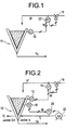
- Fig. 1 A high level partially block, partially schematic diagram of a hypothetical chemical reactor utilizing P-type feedback control is shown in Fig. 1, which illustrates a process whereby the liquid level in a conical tank 10 is being maintained by controlling the feed rate Vf of the influent liquid.
- a level controller 12 provides signals indicative of the level in tank 10 to a flow controller FC 14, which senses the liquid feed Vf and provides positioning signals to feed control valve 16 to control the liquid feed Vf to the tank 10. It will be noted that, in the system depicted in Fig. 1, the liquid out of the tank is not controlled by the flow controller 14.
- the controller 14 when the level in the conical tank is above its set-point SP, the controller 14 will reduce the fresh feed to the tank, i.e., decrease Vf, and when it's too low, the controller 14 will increase the flow, i.e., increase Vf.
- the magnitude of this adjustment is determined by the tuning parameters used, the most important of which is the gain, i.e., the proportional term ("P") in PID. In this case, the gain would be specified is units of (liters/hr)/(% level). By specifying the gain, the operator specifies how much the liquid feed Vf will be adjusted for a change in the percentage (%) deviation of the level in tank 10 from the predetermined set-point SP.
- the integral term keeps track of how long the level has been away from the predetermined set-point SP. As the area between the set-point curve and the present valve curve increases, the integral term (I) begins commanding larger changes to the liquid feed Vf.
- the derivative term (D) specifies the adjustment amount for the liquid feed Vf when the level of tank 10 is accelerating or decelerating, e.g., the change in Vf would be a first value when the level of tank 10 is increasing at an increasing rate and a second value different from the first value when the level of tank 10 is increasing at a decreasing rate.
- PID is a conventional control strategy that has been around since the 1930's; PID control is still predominant in the chemical manufacturing industry. It will be appreciated that PID control has several advantages, the greatest of which is that it does not require any special knowledge or models of the system; PID control merely requires that the operator have a deft hand at tuning the system. This strength is also its biggest weakness. More specifically, PID control doesn't take advantage of what the operator does know about the system. Thus, for the hypothetical control system illustrated in Fig. 1, the system does not take into account the fact that the tank 10 is conical. As shown in Fig. 1, the conical tank 10 is draining under gravity with the level controller 14 adjusting the flow rate of fresh feed, Vf.
- Fig. 1 The situation illustrated in Fig. 1 is further complicated if the control system has other control loops operating with respect to the tank 10, i.e., a temperature loop as shown in Fig. 2.
- the temperature 10 is preferably being controlled by adjusting the temperature Tj of the jacket fluid Vj. More specifically, a temperature sensor 18 provides a temperature signal to a temperature controller 20 controlling a heater 22, which heater heats the fluid Vj provided to the jacket 10' of tank 10. To control the tank temperature to 70°C, the temperature controller 20 changes the set-point on the jacket fluid temperature, Tj.
- controller 14 and 20 although physically isolated from one another, are nonetheless operatively coupled to one another.
- the amount of heat transferred to the tank 10 will depend on the temperature difference (T jacket - T tank ) and the surface area of contact, i.e., the heat exchange surface area.
- the temperature rise in the tank 10 depends on the mass of liquid in the tank and the heat capacity of the liquid. It will be noted that both the surface area for heat exchange and the liquid mass are strong, non-linear functions of tank level; it follows, just by inspection, that any disturbance in or change to the level in tank 10 will upset the temperature of the liquid in tank 10.
- controller 2 is to "detune" one of the controllers 14, 20, i.e., to reduce the ability of controller 20, for example, to control its variable in the interest of keeping the other controllers such as controller 12 from fighting with controller 20.
- system stability comes at the price of more drift in addition to a poorer response to a process upset.
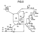
- Fig. 5 is a generalized schematic diagram of a first gas-phase reactor (GPR) 100 for olefin polymerization products.
- GPR gas-phase reactor
- Polymer is fed to the reactor 100 from the flash drum 110.
- Gas leaving the top of the reactor 100 is cooled in cooler 114 and recompressed by compressor 140. It will be noted that fresh monomers C2, C3 and hydrogen H2 are then added and the gas is fed back into the GPR 100. Gas also leaves the reactor 100 through the fines cyclone 128 and the polymer discharge valves 130, 132.
- Gas exiting the discharge valve 130, 132 eventually reaches the ethylene stripper 116, via a teal scrubber 120 and compressor 118, where much of the propylene and propane are removed and returned to the propylene bullet (not shown),while the ethylene and hydrogen H2 are returned to the reactor 100.
- Fig. 6 shows the original gas-phase reactor control scheme superimposed on the schematic diagram of Fig. 5. It will be appreciated from inspection of Fig. 6 that the lead control loop uses the calculated value for the homopolymer discharge rate from the flash drum 100 to set the ethylene flow to reactor 100 required to achieve the desired % ethylene in the final product.
- the gas composition In order for the bipolymer produced in GPR 100 to have the right composition of ethylene and propylene, the gas composition must be maintained at the right value. Since the ethylene feed has already been fixed, this is accomplished by adjusting the propylene feed rate according to the reading of the gas controller GC. In particular, hydrogen H2 is controlled to maintain the desired ratio with ethylene. It will be appreciated that the pressure in GPR 100 must be maintained within a prescribed tolerance. Since the ethylene feed is fixed, and since the propylene feed must be adjusted to keep the gas composition on target, the needed control can only be accomplished by adjusting the level of the polymer bed in the reactor 100. It should be noted that the higher the bed level, the more catalyst is provided to the system to react the gas, and vice-versa.
- Fig. 6 At the bottom of Fig. 6 is a legend listing the measurements taken using system sensors and the variables which are controlled based on these measurements.
- the conventional control scheme i.e., PID control
- the control loop is able to follow changes in the pressure very quickly, yet the pressure is controlled by changing the bed level which changes very slowly.
- the system is able to change the flow rates of the monomers very quickly, the system does not do so because the values for the gas composition change very slowly, and because the homopolymer feed is based on a filtered number.
- FIG. 7 A block diagram representing the conventional PID control strategy is shown in Fig. 7.
- each PID controller in Fig. 7 is self-contained and unable to share information with the others.
- Another similarity is that these controllers are all "coupled" to the system, as discussed above, which means that they must be tuned to respond slowly to avoid instability.
- the best example of this is the hydrogen controller 70, which tries to maintain the H2/C2 ratio in the reactor by adjusting the hydrogen feed. However, changes to the C2 feed also affect this ratio. When an upset to either the gas ratio (C2/(C2+C3)) or the pressure (total gas) occurs, the C2 hold-up will change causing the hydrogen controller 70 to react in an attempt to maintain the ratio H2/C2.
- the conventional control of the gas-phase reactor uses traditional PID controllers with no knowledge of the system controlled or the predictable interactions between the monitored and controlled variables. Because of this, PID control system loops must be tuned to react slowly to thereby minimize the effect of controller coupling. The selection of the ethylene feed as the lead controller, to which changes are allowed only very slowly, is necessary since any disturbance in the ethylene feed will upset all of the other PID controllers regulating the system.
- Linear programming models which mathematically define the relationship between the future changes of controlled variables and current and past changes in manipulated variables, are presently in use to enhance the operation of a process controller.
- a controlled variable is a process variable that is targeted to be maintained at a desired setpoint
- a manipulated variable is a variable which is adjusted to drive the controlled variable to the target value.
- An unmeasured disturbance to the process may arise e.g., from an ambient temperature change, from a change in product formulation, or from an unexpected change in demand for products.
- a process has system constraints such as temperature, pressure and flow rate which place limits on the process variables and must also be accounted for during control of the process.
- Dynamic matrix control is a process control methodology using process models to compute adjustments in manipulated variables based on a prediction of future changes in controlled variables.
- the basic concept of dynamic matrix control is to use known time domain step response process models to determine changes in manipulated variables which minimize or maximize a performance index over a specified time horizon.
- a time sequence of manipulated variable changes for each manipulated variable is computed based on the response of the process predicted by the time domain step response models such that the performance index is optimized. It will be appreciated that the DMC controller by Cutler and Ramaker is based on an approximated step response model. Therefore, the DMC controller can be only applied to open loop stable systems.
- the simplest predictive control methods such as the Minimum Variance and the Generalized Minimum Variance methods, take into account the fact that the dynamic system has an input-output delay D. Control inputs are chosen to make the system match some desired trajectory in D steps ahead. Recently, predictive controllers that consider time horizons beyond the system input-output delay (extended horizon predictive controllers) have been used in many engineering applications. The motivation for doing this is two-fold. First, the input-output delays of a dynamic system are usually not known in advance, and if the time delays are incorrectly estimated, or the delays are time varying as system operation progresses, then the system input-output stability can suffer.
- the resulting sampled dynamic system often has nonminimum phase zeros (having zeros outside the unit circle). In this case, when the choice of control is only based on the beginning of the system step response, the controller often does not perform well.
- a "predictor" that estimates future values of certain quantities related to the system outputs, based on current and past values of inputs and outputs. If the prediction horizon k extends beyond the system delay, D, then the set of (k-D) future inputs (u(t),u(t+1), ..., u(t+k-D)) must be assumed. Different predictive and adaptive predictive controllers make different assumptions (or place different constraints) on these 'extra' inputs. The predicted system outputs are then used to compute the control inputs, based upon some criterion.
- Several extended horizon predictive controllers have been developed previously. They differ in how the set of future controls is chosen.
- EHC Extended Horizon Adaptive Control
- RHC Receding Horizon Adaptive Control
- CAMAC Control Advance Moving Average Controller
- EPSAC Extended Prediction Self-Adaptive Control
- GPC Generalized Predictive Controller
- MPHC Model Predictive Heuristic Control
- DMC Dynamic Matrix Control
- the EHC predictive controller developed by Ydstie is based on an Auto-Regressive Moving-Average with auxiliary input (ARMAX) model description of the dynamic system, as described in Goodwin and Sin.
- the set of k future controls is chosen by minimization of the control effort, subject to the constraint that the k-step ahead predicted output is equal to some desired value.
- extended horizon two implementation approaches have been used: extended horizon and receding horizon implementations.
- the set of k future controls is implemented sequentially and updated every k samples.
- the receding horizon implementation of the EHC i.e., the RHC
- only the first control in the set is applied to the system.
- the whole set of k future controls is computed and again only the first one is used.
- the EHC can stabilize both open loop unstable and nonminimum phase systems.
- the RHC cannot stabilize an open loop unstable system in general.
- the CAMAC controller developed by Voss et al differs from the EHC controller in the selection of the set of future controls. In the CAMAC controller, all k future controls are assumed to be constant. This choice assures offset-free tracking performance in steady state, even without an integral action.
- the CAMAC controller can also be used for both receding horizon and extended horizon implementations. Again, the CAMAC controller can fail if the open loop system is unstable. Both the EHC and the CAMAC controllers have considered the output at only one future point in time.
- the GPC controller developed by Clarke et al extends this idea by allowing the incorporation of multi-step output predictions.
- the set of k future controls in the GPC is determined by the minimization of a quadratic cost function of predicted output tracking errors and controls, up to a horizon value into the future.
- the GPC is implemented in a receding horizon manner, as in the RHC controller.
- the GPC controller is effective for both open loop unstable and nonminimum phase systems. Because a Controlled Auto-Regressive Integrated Moving-Average (CARIMA) model is used to model the dynamic systems and to predict the output, the GPC controller always contains an integrator.
- the GPC controller includes the EPSAC controller as a special case.
- the MPHC controller by Richalet et. al. makes output predictions, based on an approximated impulse response model.
- the DMC controller by Cutler and Ramaker are based on an approximated step response model. Therefore, both MPHC and DMC controllers can be only applied to open loop stable systems. However, it should be mentioned that the DMC controller can stabilize a nonminimum phase system.
- the horizon controllers and corresponding method accomplish this partly through the use of feed-forward calculations to determine what the eventual steady-state value of the manipulated variable will be and referencing all "overshoot” and "undershoot” moves relative to this predicted value. It will be appreciated that this feature makes horizon controllers very fast in responding to an upset; however, these model-based horizon controllers are not optimized for dealing with both steady state and transient modes of operation.
- the low-pass filter always changes the value of Xf(t) relative to Xf(t-1) except when X(t) happens to exactly equal Xf(t-1). This means that it transmits all the noise, although with a reduced magnitude. Therefore, the only way to get a very smooth filtered signal from a noisy source is to have a small value of FIL and to put up with a slow response.
- What is needed is a method for controlling a chemical reactor, e.g., a gas-phase reactor, which employs on-line parametric balances, e.g., pressure and/or density balances, and non-linear modeling to simultaneously control the gas composition, pressure, and chemical content in the final product.
- on-line parametric balances e.g., pressure and/or density balances
- non-linear modeling e.g., non-linear modeling
- the principal purpose of the present invention is to provide a process control method which permits rapid adjustment and stabilization of a chemical reactor.
- the process control method matches fast control operations with fast measurements, and vice-versa, in order to optimize the process control.
- An object according to the present invention is provide a process control method which prioritizes the set points.
- the process control method of the present invention places the highest priority on maintaining the pressure at set-point, thereby stabilizing the H2/C2 ratio and gas composition.
- heat transfer and fluidization will be more consistent due to a stable gas density when pressure is the parameter which is preferentially controlled.
- manipulated variables are grouped to facilitate transient and steady-state system response
- Another object according to the present invention is to provide a process control method which employs parametric balances and mathematical models for the controlled reactor to thereby allow the controller implementing the process control method to react more accurately and quickly to perturbations across a wide range of operating parameters.
- the process control method permits automatic transitions between various product types.
- Still another object according to the present invention is to provide a process control method which uses parametric balances and mathematical models for the controlled reactor to thereby allow the controller implementing the process control method to perform set-point changes relatively rapidly. It will be appreciated that the descriptions of relative speeds and reaction rates mentioned above are with respect to an identical system under the control of a conventional PID control system.
- N-sign filters where N is a positive integer, with relatively high values of N producing a smoother signal but with greater delay than low values of N, all meet these operating criteria.
- an exemplary, modified N-sign filter where N equals 3, satisfies these seemingly exclusive criteria: it gives a very smooth output signal at steady-state even for a noisy input; and it does not delay the output signal significantly when the input is undergoing a rapid change.
- Yet another object according to the present invention is to provide a process control method for filtering one of a received signal or a steady-state output signal generated, in an exemplary case, by the horizon controller.
- Still another object according to the present invention is to provide a process control method for filtering an input signal, wherein the dead-band width of the filter is proportional to the noise in the signal in a first range and wherein dead-band width of the filter is established according to the maximum allowable value of the delay in the filter output signal, thereby accepting more noise in the output signal.
- Another object according to the present invention is to provide a process control method for filtering an input signal, wherein the dead-band width can be reduced with the addition of data points processed by the filter (algorithm).
- the solution to controlling a non-linear coupled system is to incorporate what is known about the system into process models and then to use these models to predict the effect of any change on the system.
- the volume of liquid required for a given, level, the surface, and even the exit flow out the bottom can easily be calculated. From there, it is a relatively simple matter to determine what change needs to be made in the fresh feed Vf and jacket temperature Jt in order to achieve and maintain the set-points.
- level control method employed with the system of Fig. 8 will not actually control the level in tank 10 at all; the control method actually controls the calculated mass hold-up of liquid in the reactor.
- the process control method according to the present invention applies a penalty in that a larger amount of system data must be monitored in order to achieve the desired control.
- tank level, tank temperature, effluent flow rate Ve, feed flow rate Vf, and feed temperature must all be measured and corresponding data must be passed to the model for use in the extensive property balances, e.g., pressure and/or density balances, and model-based control method calculations.
- the set-points for the feed flow Vf and jacket temperature Jt are then passed back to the slave controllers FC and TC after every execution of the process control method.
- the fictitious stream Vd illustrated in Fig. 8 represents any unmeasured discharge from tank 10 together with model and measurement errors.
- NMPC Non-linear Model Predictive Control
- the NMPC method preferably controls the gas pressure for each ingredient in the GPR using horizon control technology.
- the NMPC method uses the same set-points as used by conventional PID controllers: H2/C2 ratio; gas ratio; pressure; and C2/homopolymer ratio, which greatly simplifies migration to, and training in, the NMPC methodology.
- the NMPC method is a multivariable control method, in contrast with the conventional practice which employs four individual PID controllers.
- the conventional PID controllers must be tuned to be very slow to react so as to avoid instability effects due to, for example, controller coupling. It will be appreciated that this results in frequent set-point offsets.
- the NMPC method predicts the interactions between the various measured parameters so that a controller operating in accordance with the NMPC method can be tuned more aggressively, giving to the NMPC controller both more stability and quicker response to set-point changes.
- the NMPC method was first tested on a simulator, which is normally used for operator training. It will be appreciated that since the simulator was designed to have accelerated dynamics to challenge operators, the simulator provided a severe test bed for evaluation of a controller operating in accordance with the NMPC method. The simulator was used in the assessment to test the overall NMPC control method concept as well as to show the NMPC method's response to severe disturbances. The tests on the simulator were performed over several months. It will be appreciated that the simulator's use was not limited solely to demonstrating the concept of NMPC control, it also served to prepare the technical and operating staff for the plant trial. The simulator was used as a pass or fail test, before allowing any plant test, which testing is described in greater detail immediately below.
- Fig. 11 illustrates the control scheme, i.e., the NMPC method according to the present invention, wherein a lead controller manipulates the feed of constituents, e.g., ethylene and propylene, in order to maintain the pressure in GPR 100 within very tight bounds.
- constituents e.g., ethylene and propylene
- the gas composition GC must be maintained, and this is advantageously preformed by adjusting the ratio of ethylene to propylene in the monomer feed.
- a faster response advantageously can be achieved by using an IR sensor to determine the gas-ratio every second instead of using the GC to obtain the gas ratio approximately every six minutes.
- a new sensor using infra-red (IR) spectroscopy permits measurement of the ethylene and propylene content in the gas phase of the GPR 100.
- the IR spectroscope provides a continuous signal which is then reconciled with chromatograph values. Invisible to the IR, the hydrogen must still be controlled using only the GC.
- the full benefit of the IR spectroscope advantageously can be seen when the NMPC method is used for sensing and controlling transitions involving the gas ratio, and during other system perturbations.
- the end product of the exemplary GPR 100 control system illustrated in Fig. 11 must have the proper ethylene content. Therefore, the NMPC method must insure that, on average, the ratio of the ethylene feed to the homopolymer feed is the same as that which would have been used in a GPR having a control system using conventional PID control. It will be appreciated that this control was previously accomplished by adjusting the ethylene feed directly. In contrast, the ethylene feed cannot be completely controlled in an effort to control ethylene content since the ethylene feed is being partially set by the pressure controller P in the system employing the NMPC method. Instead, the NMPC method according to the present invention maintains the polymer bed in the reactor 100 at the level which causes the pressure controller P to feed the quantity of ethylene required.
- the NMPC method places the lead controller on the most important variable, e.g., pressure in the GPR 100 under discussion.
- pressure e.g., pressure in the GPR 100 under discussion.
- the system also maintains the gas density which affects the fluidization and heat transfer in the reactor 100.
- a steady pressure advantageously will stabilize the flows of gas into the reactor 100 from the flash drum 110 and out of the reactor 100 to the bag filter 122, making it easier to maintain the proper gas composition, since propylene enters the reactor 100 from the flash drum 110 and leaves the reactor 100 via the ethylene stripper 116.
- Another advantage to the NMPC method according to the present invention is the matching of response times.
- the pressure reading is available every few seconds; the system controller using the NMPC method controls pressure in GPR 100 with the monomer feeds, which advantageously can be changed very quickly.
- FIG. 12 A high level block diagram of the controller implementation the NMPC method according to the present invention is shown in Fig. 12. It will be appreciated that the change in control philosophy reflected by the NMPC method has been made possible by using process models to decouple the system controllers. Unlike the conventional PID control scheme, which uses intensive variables, i.e., variables not based on quantity such as H2/C2 ratio, C2/(C2+C3) ratio, and C2/PP ratio (analogous to level in the conical tank), the model-based NMPC method controls the GPR 100 based on extensive variables, e.g.,. mass hold-up of each component in the reactor 100 or pressure in the GPR 100 or density of the reactants in the GPR 100. For example, the set-point for gas composition, together with the volume of the system, readily allows determination of how many kilograms of each component are required to achieve the desired system target.
- intensive variables i.e., variables not based on quantity such as H2/C2 ratio, C2/(C2+C3) ratio
- the C2 controller 160 will respond and the H2 controller will not, thus allowing the H2/C2 ratio to deviate from target, since the control system utilizing the NMPC method knows that the right amount of hydrogen H2 is already present in the GPR 100. In this manner, when the C2 disturbance has been eliminated, the C2 set-point will be re-established. Additionally, it will be appreciated that the mass balances made for each component allow prediction of corrections are needed to respond to a change of a set-point or disturbance in the reactor 100.
- the NMPC method by applying the knowledge of the system to create controllers based on extensive system properties, makes it possible to decouple the system, thus allowing fast action by all of the individual controllers in the system without sacrificing system stability.
- the use of parametric balances permits the controllers implementing the NMPC method to anticipate problems and respond accordingly to minimize the effects of disturbances and to allow fast transitions, i.e., set-point changes.
- the NMPC method according to the present invention was tested on an actual operating gas-phase reactor under both steady state and transient conditions for various products.
- the plant test results are presented below. It is important to note that the actual plant trial was conducted with essentially no disturbances to the production, which is always a first objective throughout any process control development. The control strategy commissioning and testing on the actual plant was completed within only two weeks in total.
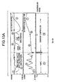
- the controller employing the NMPC method performed very well, reducing the coefficient of variation (COV) for H2/C2 relative to the conventional controller using PID control by a factor of 2 for a first product and a factor of 5 for a second product. See Fig. 13A. More specifically, the following differences were achieved:
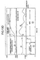
- the system controller implementing the NMPC method was also used to stabilize the hydrogen after a transition from the first product into the Second product, as illustrated in Fig. 13D.
- the H2/C2 ratio was 75 ppm from set-point and was in a roll caused by the slow action of the conventional PID controller.
- the controller utilizing the NMPC method immediately broke the roll and brought the H2/C2 ratio to target in approximately 1.0 hour. Without the NMPC method, the roll would have lasted for up to 10 additional hours, with decreasing amplitude.
- the results depicted in Fig. 13D are as follows:
- the NMPC method according to the present invention was used at the end of a transition going from the first product to the Second product to stabilize the gas ratio, as illustrated in Fig. 13E.
- the move was made going from 0.472 to 0.460.
- the C2 reached its new target within the specified 40 minutes, while C3 took 60 minutes due primarily to the limited rate of change that was allowed on the C3 flow.
- the estimated 40 minute transition time, and even the somewhat long actual transition time compares very well with the 3 hours required for a similar change using conventional PID control.
- the results depicted in Fig. 13E are as follows:
- a digital filter has been developed which improves significantly over the performance of the low-pass filters now commonly in use in conventional applications in that the novel filter gives a very stable steady-state signal while still responding quickly to movement in the input.
- the horizon controllers now being installed in many chemical plants use a conventional NMPC method to give feed-forward response to set-point changes or process upsets. This feature, however, makes them susceptible to noise in the signals that are used for the horizon calculations. Moreover, unwanted noise in the signals corresponding to the measured parameters can cause the horizon controllers to swing the manipulated variable excessively, thus upsetting other control loops.
- the N-sign filter according to the present invention advantageously provides a very smooth signal with virtually no delay, which leads to dramatically reduced movement of the manipulated variable and an overall stabilizing of the NMPC process.
- the advantages associated with the N-sign filter were demonstrated using a dynamic simulation of the density horizon controller, which horizon controller had been seen as being highly susceptible to noise in the sensed signals.
- the algorithm representing the N-sign filter according to the present invention can be easily implemented in any conventional controller with modest programming capabilities.
- the N-sign filter is implemented as a stand alone device, which advantageously can be disposed at any point in the control system, i.e., either upstream or down stream of a horizon controller. It should noted be that the N-sign filter is not limited in its application to horizon controllers; the performance of conventional PID controllers advantageously should be improved as well by use if the N-sign filter.
- a density horizon controller employing the NMPC method according to the present invention uses the production rate value from the parametric, e.g., thermal, balance to determine what the steady-state monomer feed must be.
- Noise in the production rate signal will cause swings in the monomer feed, which upsets the temperature control, the pressure drum, and the back end of the GPR 100. Therefore, the production rate signal used by the horizon controller must be smoothed.
- a conventional low-pass filter provides a very smooth output signal only at the expense of a delay of many minutes to any movements in the input signal, which hampers the performance of the horizon controller. It will be appreciated that significant signal delay may lead eventually to oscillations in the loop density.
- the development of the N-sign filter was motivated by the desire to find a more efficient way of filtering the input signals that would provide a very smooth signal at steady-state without introducing a appreciable delay, i.e., time lag, in the signal provided to the horizon controller for use in predictive calculations.
- the goal of the investigation which lead to the N-sign filter work was to develop a filter that would not change its signal in response to noise and yet would be able to respond quickly to true changes in the underlying signal.
- the filter presented immediately below, designated the N-sign filter meets these criteria.
- the N-sign filter was designed with the needs of the horizon controller in mind, the N-sign filter advantageously will improve the performance of conventional PID controllers as well.
- the low-pass filter always changes the value of Xf(t) relative to Xf(t-1) except when X(t) happens to exactly equal Xf(t-1). This means that it transmits all the noise, although with a reduced magnitude. Therefore, the only way to get a very smooth filtered signal from a noisy source is to have a small value of FIL and to put up with a slow response.
- the control system examines the last N, e.g., 3, raw data points and compares the raw data points with the value of the filtered signal that immediately precedes them. It will be appreciated that the immediately preceding filtered signal is in no way influenced by the N raw data points. When the N raw data points all lie on one side of that immediately preceding filtered signal point, the next value of the filtered signal will advantageously move toward the N raw data points, as discussed in greater detail below. However, when the N raw dat points lie on both sides of the immediately preceding filtered signal point, the N raw data points are considered to represent noise. For that reason, the immediately preceding filtered signal will change little in response to the N raw data points.
- X(t) raw data point at time t
- Xf(t) filtered signal at time t
- f3 SIGN [ X(t) - Xf(t-3) ] *
- 1.0 f2 SIGN [ X(t-1) - Xf(t-3) ]
- 1.0 f1 SIGN [ X(t-2) - Xf(t-3) ] *
- 1.0 fsum f1+f2+f3
- the basic N-sign filter is a low-pass filter with the term FIL being multiplied by a new term, FAC.
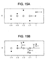
- the SIGN function is employed to determine whether it lies above or below the reference filtered signal value, Xf(t-3), i.e., the most recent value of the filtered signal not affected by the three raw data points. See Fig. 15.
- FAC ( ABS ( fsum )/3 ) z
- the value of Z is selected based on how much noise suppression is required at steady-state.
- the basic N-sign filter can be thought of as a low-pass filter with two possible values of FIL: one for response to signal changes (e.g. fsum equals 3), FIL1, and one for steady-state noise suppression (e.g. fsum equals 1), FIL2. See TABLE II, below.
- FIL1 FIL * (1)
- FIL2 FIL * (1/3) z
- Fig. 15A shows the raw data points - denoted X, and the filtered signal - denoted Xf.
- Xf the filtered signal
- Fig. 15B shows the point Xf(t-3) is the reference for determining the values f1, f2, and f3, since the point Xf(t-3) is the last point which is not influenced by the latest three raw data points.
- Xf(t-3) was used as the point of reference for determining whether X(t) represents a true signal shift or just noise. It will also be appreciated that the reference point for calculating Xf(t), however, is Xf(t-1), as shown in Fig. 15C.
- the "FACTOR” terms can be calculated in many different ways to customize the behavior of the signal.
- the simplest way to calculate these terms is to allow FACTOR only the discrete values of 0 inside the dead-band and 1 outside of it, as shown in Fig. 16C.
- two of the three points lie out of the dead-band, so the value of FAC is no longer negligible.
- moving Xf(t) upward seems the appropriate step. If, however, X(t-1) had fallen below the value of Xf(t-3), it would seem wiser not to move Xf(t). This is accomplished as discussed in greater detail below.
- fsum can now take on a continuum of values from -3 to 3. As will be discussed in greater detail below, this allows the N-sign filter to gradually eliminate offsets.
- a further refinement to the N-sign filter is to increase the penalty for any raw data point on the opposite side of Xf(t-3) from the other two raw data point.
- This advantageously can be performed by truncating the value of fsum (shown below with the FORTRAN intrinsic function INT).
- an alternative preferred embodiment of the N-sign filter can be constructed either as a stand alone unit or using a general purpose controller, e.g., the horizon controller employing the NMPC method according to the present invention to perform the algorithm set forth in Equations (49) - (60 ), which are presented immediately below.
- a general purpose controller e.g., the horizon controller employing the NMPC method according to the present invention to perform the algorithm set forth in Equations (49) - (60 ), which are presented immediately below.
- X(t) raw data point at time t
- Xf(t) filtered signal at time t.
- the N-sign filter algorithm is performed as a series of steps as set forth below.
- fsum INT ( ABS ( f1+f2+f3+...+fn ) ) when an integer representation of fsum advantageously can be employed.
- a digital signal filter has been developed which satisfies two seemingly mutually exclusive criteria: it provides a very smooth signal at steady-state, yet it is also quick to respond to a change. This makes it ideal for the smoothing of signals used by a horizon controller.
- Fig. 18A shows the exemplary signal that was used in all the tests of the N-sign filter. While the N-sign filter described can be used on any signal, the production rate was used as the test case so that the effect of smoothing the signal has on the density horizon controller can readily be illustrated.
- the true signal starts at SPA Kg/hr, rises within 5 minutes to SPB Kg/hr as it might with the sudden addition of H2 or C2, levels off for 100 minutes, and then drops slowly back to SPA Kg/hr over the course of 100 minutes as it might in response to a cut back in the catalyst feed.
- the test signal shows the three kinds of behavior that we must use to evaluate our filtering methods: steady-state, sudden change, and slow drift.
- the "measured” signal Superimposed on the “true” signal in Fig. 18A is the “measured” signal, which in this case includes noise with a maximum magnitude of 200 Kg/hr. This "measured” signal is what will be fed to the filters to determine their ability to provide a smooth yet responsive output signal.
- the first filter tested was the standard low-pass filter.
- the output of the low-pass filter illustrated in Fig. 18C depicts as acceptably smooth steady-state signal, but at the cost of a very slow response to any change in the underlying signal, as evidenced by the need for more than 25 minutes for the filtered signal to reach SPB Kg/hr. It should be mentioned that the benefit derived from the use of horizon controllers, makes this delayed signal clearly unacceptable. It will also be appreciated that it was exactly the situation illustrated in Fig. 18C which motivated the search for a better way to smooth the steady-state.
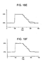
- Fig. 18E shows how markedly the N-sign filter is improved with the addition of a dead-band with a half-width of 200 Kg/hr.
- Fig. 18E shows the signal given by the N-sign filter with dead-band to allow continuous values of the "FACTOR” terms from 0 to 1 (instead of only 0 inside the dead-band and 1 outside of the dead-band). This improves the response to the slow drift, making it smoother, at the expense of a slightly noisier signal at steady-state. The additional noise can be largely eliminated by truncating the value of "fsum" as shown in Fig.
- the rough edges of the filtered signal such as the spike after the move to SPB Kg/hr, can be smoothed by using a 3 point moving average of the measured values, as shown in Fig. 18H. This does slow the response to the step-change slightly, which can be compensated for by raising the value of FIL.
- Fig. 18I shows the "measured" value of R1 together with two filtered values a low-pass filter and an optimized N-sign filter.
- Fig. 18J contrasts the monomer feed set-point generated from the N-sign filter value of R1 with that using the low-pass signal.
- the horizon controller using the low-pass value is changing the monomer set-point every minute. This is destabilizing to the other control loops, especially the temperature and pressure drum controllers.
- the horizon controller using the N-sign filter is very steady, which will have a strong stabilizing effect on the rest of the plant. Yet, it still retains the ability to respond quickly to a true change in the underlying signal.
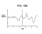
- Fig. 18K contrasts the density curve of the controller using the low-pass filter with that using the N-sign filter. In both cases, the control is excellent, maintaining the density within +/-0.7 grams/liter despite a very large swing in the production rate. Ironically, the density is maintained more tightly with large swings in the monomer feed, but this is clearly unacceptable due to the destabilizing effect on the rest of the plant.
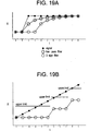
- Fig. 19A demonstrates how, in the absence of noise, the signal of the N-sign filter is delayed N-1 time intervals relative to that of a low-pass filter.
- the response becomes a stair-step since virtually no change is made to the output signal until N points are outside of the dead-band, as shown in Fig. 19B.
- the time interval used by the N-sign filter can be much smaller than that of the horizon controller that is using the signal and is limited only by the frequency at which the raw data values become available. For example, when the density horizon controller is executing once a minute, the N-sign filter operating at the production rate could easily be updated every 20 seconds. It will be appreciated that this would neutralize the effect of the N-1 interval delay.
- the design of the N-sign filter is easily extended to 4, 5, or any other number of points, as discussed in greater detail above.
- the cost is a longer delay which would require even more frequent execution to eliminate the delay.
- Figs. 19C and 19D show the response curves for 4- and 5- sign filters, respectively. It should be noted that while adding points to the basic N-sign filter gives a much smoother signal, the improvement with respect to the modified N-sign filter shown in Fig. 18H is very slight; it is doubtful that the use of additional raw data points is worth the extra effort.
- the value of Z is adjusted based on how much action is desired when all three points are not outside the dead-band and on the same side, i.e., when fsum ⁇ 1.
- the best value for the dead-band is usually going to be roughly equal to the magnitude of the noise in the signal.
Landscapes
- Engineering & Computer Science (AREA)
- Health & Medical Sciences (AREA)
- General Physics & Mathematics (AREA)
- Computer Vision & Pattern Recognition (AREA)
- Evolutionary Computation (AREA)
- Medical Informatics (AREA)
- Software Systems (AREA)
- Physics & Mathematics (AREA)
- Artificial Intelligence (AREA)
- Automation & Control Theory (AREA)
- Chemical & Material Sciences (AREA)
- Chemical Kinetics & Catalysis (AREA)
- Medicinal Chemistry (AREA)
- Polymers & Plastics (AREA)
- Organic Chemistry (AREA)
- Feedback Control In General (AREA)
- Physical Or Chemical Processes And Apparatus (AREA)
- Electrophonic Musical Instruments (AREA)
- Feeding, Discharge, Calcimining, Fusing, And Gas-Generation Devices (AREA)
Claims (10)
- Verfahren zum Steuern eines chemischen Reaktors mit nichtlinearer prädiktiver Steuerung, wobei das Verfahren folgende Schritte umfasst:Bereitstellen eines nichtlinearen prädiktiven Modells basierend auf mindestens einer extensiven Variablen und mit der Form manipulierte Veränderliche = stationäre(s) Glied(er) + dynamische(s) Glied(er) + Fehlerglied;Erzeugen einer Mehrzahl von Signalen, die einen aktuellen Zustand des chemischen Reaktors darstellen und ein jeweiliges Bestandteil von Reaktionsteilnehmern in dem chemischen Reaktor widerspiegeln;Berechnen eines zukünftigen Zustands des chemischen Reaktors, der auf die Mehrzahl von Signalen antwortet und der auf die Massenretention der Reaktionsteilnehmer in dem chemischen Reaktor referenziert ist; undSteuern mindestens einer der manipulierten Veränderlichen, um den zukünftigen Zustand des chemischen Reaktors zu steuern.
- Verfahren gemäß Anspruch 1, bei dem der Steuerschritt vorzugsweise den Druck in dem chemischen Reaktor steuert, um eine vorbestimmte Dichte der Reaktionsteilnehmer in dem chemischen Reaktor beizubehalten.
- Verfahren gemäß Anspruch 2, bei dem der chemische Reaktor ein Gasphasenreaktor ist, und wobei der Steuerschritt vorzugsweise den Druck in dem Gasphasenreaktor steuert, um eine vorbestimmte Gasdichte in dem Gasphasenreaktor beizubehalten.
- Verfahren gemäß Anspruch 1, ferner mit dem Schritt zum Filtern der Signale mittels einer N-Vorzeichen-Filtersubroutine, die ein Rohsignal der Mehrzahl von Signalen mit einem gefilterten Signal ersetzt, das mittels N letzter Rohsignale und einem direkt vorhergehenden gefilterten Signal berechnet wurde, wobei N eine positive ganze Zahl ist.
- Verfahren gemäß Anspruch 4, bei dem der Filterschritt einen Algorithmus ausführt, der wie folgt ausgedrückt wird:X(t) = Rohdatenpunkt zur Zeit t;Xf(t) = gefiltertes Signal zur Zeit t;n eine positive ganze Zahl ist;z eine positive Zahl ist;SIGN eine Funktion ist, die das Vorzeichen eines jeweiligen Ausdrucks zurückgibt;FIL eine reelle Zahl ist, die die Änderungsrate des gefilterten Signals zur Zeit t angibt; undABS eine Absolutwertfunktion ist.
- Verfahren gemäß Anspruch 1, bei dem der Berechnungsschritt ein Berechnen des zukünftigen Zustands des chemischen Reaktors, der auf die Mehrzahl von Signalen anspricht, und hinsichtlich extensiver Variablen, die den Reaktionsteilnehmern in dem chemischen Reaktor entsprechen, umfasst.
- Verfahren gemäß Anspruch 1, wobei das Verfahren ferner den folgenden Schritt umfasst:Erzeugen gefilterter Signale, die ausgewählten Signalen der Signale entsprechen, die auf mindestens drei Rohdatenpunkte ansprechen, und eines verarbeiteten jeweiligen Signals, das keine der drei Rohdatenpunkte aufweist; wobei:der zukünftige Zustand des chemischen Reaktors, der auf mindestens ein Signal der gefilterten Signale und nicht ausgewählten Signale der Signale anspricht, hinsichtlich extensiver Variablen, die den Reaktionsteilnehmern in dem chemischen Reaktor entsprechen, berechnet wird;der Schritt zum Erzeugen eines gefilterten Signals vor dem Durchführen des Berechnungsschritts durchgeführt wird.
- Verfahren gemäß Anspruch 7, bei dem der Steuerschritt vorzugsweise den Druck in dem chemischen Reaktor steuert, um eine vorbestimmte Dichte der Reaktionsteilnehmer in dem chemischen Reaktor beizubehalten.
- Verfahren gemäß Anspruch 7, bei dem der chemische Reaktor ein Gasphasenreaktor ist, und wobei der Steuerschritt vorzugsweise den Druck in dem Gasphasenreaktor steuert, um eine vorbestimmte Gasdichte in dem Gasphasenreaktor beizubehalten.
- Verfahren gemäß Anspruch 7, bei dem die gefilterten Signale gemäß einem wie folgt ausgedrückten Algorithmus erzeugt werden:X(t) = Rohdatenpunkt zur Zeit t;Xf(t) = gefiltertes Signal zur Zeit t;n eine positive ganze Zahl ist;z eine positive Zahl ist;SIGN eine Funktion ist, die das Vorzeichen eines jeweiligen Ausdrucks zurückgibt;FIL eine reelle Zahl ist, die die Änderungsrate des gefilterten Signals zur Zeit t angibt; undABS eine Absolutwertfunktion ist.
Priority Applications (1)
| Application Number | Priority Date | Filing Date | Title |
|---|---|---|---|
| EP03018230A EP1365296B1 (de) | 1997-12-23 | 1998-12-19 | Verfahren zur Erzeugung eines gefilterten Signals sowie ein numerisches Flter. |
Applications Claiming Priority (2)
| Application Number | Priority Date | Filing Date | Title |
|---|---|---|---|
| US08/996,853 US6122557A (en) | 1997-12-23 | 1997-12-23 | Non-linear model predictive control method for controlling a gas-phase reactor including a rapid noise filter and method therefor |
| US996853 | 1997-12-23 |
Related Child Applications (1)
| Application Number | Title | Priority Date | Filing Date |
|---|---|---|---|
| EP03018230A Division EP1365296B1 (de) | 1997-12-23 | 1998-12-19 | Verfahren zur Erzeugung eines gefilterten Signals sowie ein numerisches Flter. |
Publications (3)
| Publication Number | Publication Date |
|---|---|
| EP0926576A2 EP0926576A2 (de) | 1999-06-30 |
| EP0926576A3 EP0926576A3 (de) | 1999-11-24 |
| EP0926576B1 true EP0926576B1 (de) | 2004-05-06 |
Family
ID=25543374
Family Applications (2)
| Application Number | Title | Priority Date | Filing Date |
|---|---|---|---|
| EP98124146A Expired - Lifetime EP0926576B1 (de) | 1997-12-23 | 1998-12-19 | Nichtlineare modellgestützte prädiktive Regelungsmethode zur Regelung eines Gasphasenreaktors. |
| EP03018230A Expired - Lifetime EP1365296B1 (de) | 1997-12-23 | 1998-12-19 | Verfahren zur Erzeugung eines gefilterten Signals sowie ein numerisches Flter. |
Family Applications After (1)
| Application Number | Title | Priority Date | Filing Date |
|---|---|---|---|
| EP03018230A Expired - Lifetime EP1365296B1 (de) | 1997-12-23 | 1998-12-19 | Verfahren zur Erzeugung eines gefilterten Signals sowie ein numerisches Flter. |
Country Status (11)
| Country | Link |
|---|---|
| US (2) | US6122557A (de) |
| EP (2) | EP0926576B1 (de) |
| JP (1) | JPH11249705A (de) |
| KR (1) | KR19990063354A (de) |
| CN (2) | CN100426673C (de) |
| AT (2) | ATE266220T1 (de) |
| AU (1) | AU9812498A (de) |
| BR (1) | BR9805624A (de) |
| CA (2) | CA2255314C (de) |
| DE (2) | DE69823633T2 (de) |
| TW (1) | TW430758B (de) |
Families Citing this family (64)
| Publication number | Priority date | Publication date | Assignee | Title |
|---|---|---|---|---|
| JP3281867B2 (ja) * | 1998-08-05 | 2002-05-13 | 三菱重工業株式会社 | 信号処理装置 |
| US6284196B1 (en) * | 1999-04-01 | 2001-09-04 | Bp Corporation North America Inc. | Apparatus for monitor and control of an ammoxidation reactor with a fourier transform infrared spectrometer |
| DE60102242T2 (de) * | 2000-06-29 | 2005-01-27 | Aspen Technology, Inc., Cambridge | Rechnerverfahren und gerät zur beschränkung einer nicht-linearen gleichungsnäherung eines empirischen prozesses |
| DE10033183C2 (de) * | 2000-07-07 | 2002-08-08 | Max Planck Gesellschaft | Verfahren und Vorrichtung zur Verarbeitung und Vorhersage von Strömungsparametern turbulenter Medien |
| US6760631B1 (en) | 2000-10-04 | 2004-07-06 | General Electric Company | Multivariable control method and system without detailed prediction model |
| KR100812491B1 (ko) * | 2001-03-02 | 2008-03-11 | 포위텍 인텔리전트 테크놀로지스 게엠베하 | 열역학적 과정을 제어하기 위한 방법 |
| JP4677679B2 (ja) * | 2001-03-27 | 2011-04-27 | 株式会社デンソー | 製品の製造プロセスにおける特性調整方法 |
| US20030028267A1 (en) * | 2001-08-06 | 2003-02-06 | Hales Michael L. | Method and system for controlling setpoints of manipulated variables for process optimization under constraint of process-limiting variables |
| CN1329110C (zh) * | 2001-09-26 | 2007-08-01 | 伊内奥斯美国公司 | 一体化的化工工艺控制 |
| US20030144747A1 (en) * | 2001-11-21 | 2003-07-31 | Metso Paper Automation Oy | Method and controller to control a process |
| US7846736B2 (en) * | 2001-12-17 | 2010-12-07 | Univation Technologies, Llc | Method for polymerization reaction monitoring with determination of entropy of monitored data |
| US7226789B2 (en) * | 2001-12-17 | 2007-06-05 | Unication Technolofies, Llc | Method of applying non-linear dynamics to control a gas-phase polyethylene reactor operability |
| AU2003218413A1 (en) * | 2002-03-29 | 2003-10-20 | Agilent Technologies, Inc. | Method and system for predicting multi-variable outcomes |
| CA2513091A1 (en) * | 2003-01-31 | 2004-08-19 | Fakhruddin T. Attarwala | Integrated optimization and control using modular model predictive controller |
| US7783617B2 (en) * | 2003-04-16 | 2010-08-24 | Yahoo! Inc. | Personals advertisement affinities in a networked computer system |
| US7242989B2 (en) * | 2003-05-30 | 2007-07-10 | Fisher-Rosemount Systems, Inc. | Apparatus and method for batch property estimation |
| US6813895B2 (en) * | 2003-09-05 | 2004-11-09 | Carrier Corporation | Supercritical pressure regulation of vapor compression system by regulation of adaptive control |
| US8109766B2 (en) | 2003-10-03 | 2012-02-07 | Global Nuclear Fuel-Americas Llc | Method for predicted reactor simulation |
| US8676830B2 (en) * | 2004-03-04 | 2014-03-18 | Yahoo! Inc. | Keyword recommendation for internet search engines |
| US8914383B1 (en) | 2004-04-06 | 2014-12-16 | Monster Worldwide, Inc. | System and method for providing job recommendations |
| US7739142B2 (en) * | 2004-05-17 | 2010-06-15 | Yahoo! Inc. | System and method for providing automobile marketing research information |
| CN100340933C (zh) * | 2004-06-15 | 2007-10-03 | 袁璞 | 连续生产化学反应器的控制系统 |
| US7502715B1 (en) * | 2004-09-21 | 2009-03-10 | Asml Netherlands B.V | Observability in metrology measurements |
| CN1295576C (zh) * | 2004-11-04 | 2007-01-17 | 浙江大学 | 槽式反应器基于支持向量机的非线性模型预测控制方法 |
| US20060206517A1 (en) * | 2005-03-11 | 2006-09-14 | Yahoo! Inc. | System and method for listing administration |
| WO2006099299A2 (en) * | 2005-03-11 | 2006-09-21 | Yahoo! Inc. | System and method for managing listings |
| US8433713B2 (en) | 2005-05-23 | 2013-04-30 | Monster Worldwide, Inc. | Intelligent job matching system and method |
| US8375067B2 (en) * | 2005-05-23 | 2013-02-12 | Monster Worldwide, Inc. | Intelligent job matching system and method including negative filtration |
| US8527510B2 (en) * | 2005-05-23 | 2013-09-03 | Monster Worldwide, Inc. | Intelligent job matching system and method |
| US7809551B2 (en) * | 2005-07-01 | 2010-10-05 | Xerox Corporation | Concept matching system |
| US7947797B2 (en) * | 2005-09-14 | 2011-05-24 | Univation Technologies, Llc | Method for operating a gas-phase reactor at or near maximum production rates while controlling polymer stickiness |
| US8195657B1 (en) | 2006-01-09 | 2012-06-05 | Monster Worldwide, Inc. | Apparatuses, systems and methods for data entry correlation |
| US8600931B1 (en) | 2006-03-31 | 2013-12-03 | Monster Worldwide, Inc. | Apparatuses, methods and systems for automated online data submission |
| US12314907B2 (en) | 2006-03-31 | 2025-05-27 | Monster Worldwide, Inc. | Apparatuses, methods and systems for automated online data submission |
| US20070288308A1 (en) * | 2006-05-25 | 2007-12-13 | Yahoo Inc. | Method and system for providing job listing affinity |
| US7826909B2 (en) * | 2006-12-11 | 2010-11-02 | Fakhruddin T Attarwala | Dynamic model predictive control |
| US8032235B2 (en) * | 2007-06-28 | 2011-10-04 | Rockwell Automation Technologies, Inc. | Model predictive control system and method for reduction of steady state error |
| EP2055720A1 (de) * | 2007-11-05 | 2009-05-06 | Total Petrochemicals Research Feluy | Modell zur Vorhersage der Dichte und des Schmelzindex eines einen Kreislaufreaktor verlassenden Polymers |
| EP2055721A1 (de) * | 2007-11-05 | 2009-05-06 | Total Petrochemicals Research Feluy | Verfahren zum Optimieren des Übergangs eines Polymertypes zu einem anderen |
| US8244551B1 (en) | 2008-04-21 | 2012-08-14 | Monster Worldwide, Inc. | Apparatuses, methods and systems for advancement path candidate cloning |
| US20100082356A1 (en) * | 2008-09-30 | 2010-04-01 | Yahoo! Inc. | System and method for recommending personalized career paths |
| US8260440B2 (en) * | 2008-12-05 | 2012-09-04 | The Regents Of The University Of Michigan | Adaptive control based on retrospective cost optimization |
| KR101737308B1 (ko) * | 2008-12-29 | 2017-05-18 | 바셀 폴리올레핀 이탈리아 에스.알.엘 | 기상 중합 반응기 제어 |
| US8155764B2 (en) * | 2009-02-27 | 2012-04-10 | Honeywell International Inc. | Multivariable model predictive control for coalbed gas production |
| US9063540B2 (en) * | 2009-04-07 | 2015-06-23 | Fisher Controls International Llc | Methods and apparatus to limit a change of a drive value in an electro-pneumatic controller |
| DE102011003477B4 (de) * | 2011-02-01 | 2015-07-02 | Siemens Aktiengesellschaft | Verfahren und Vorrichtung zur Filterung eines Signals und Regeleinrichtung für einen Prozess |
| US20130346460A1 (en) * | 2011-01-11 | 2013-12-26 | Thierry Bruneau | Method and device for filtering a signal and control device for a process |
| DE102011016804B4 (de) | 2011-04-12 | 2016-01-28 | Drägerwerk AG & Co. KGaA | Vorrichtung und Verfahren zur Datenverarbeitung physiologischer Signale |
| DE102011115034A1 (de) | 2011-10-07 | 2013-04-11 | Voith Patent Gmbh | Verfahren zur Primärregelung eines Wasserkraftwerks |
| CN103034122A (zh) * | 2012-11-28 | 2013-04-10 | 上海交通大学 | 基于时间序列的多模型自适应控制器及控制方法 |
| US8986618B2 (en) | 2013-06-28 | 2015-03-24 | Ineos Usa, Llc | System and method for rapid transitioning of polyolefin processes from one product to another |
| US20170330153A1 (en) | 2014-05-13 | 2017-11-16 | Monster Worldwide, Inc. | Search Extraction Matching, Draw Attention-Fit Modality, Application Morphing, and Informed Apply Apparatuses, Methods and Systems |
| CN109074051B (zh) * | 2016-03-28 | 2021-06-11 | 三菱电机株式会社 | 质量管理装置、质量管理方法及记录介质 |
| CN105954714A (zh) * | 2016-05-12 | 2016-09-21 | 长安大学 | 一种隧道人员定位系统及方法 |
| CN108121215B (zh) * | 2017-09-12 | 2018-11-16 | 山东科技大学 | 基于全回路重构仿真的工业控制回路性能评价方法及装置 |
| CN109489683A (zh) * | 2017-09-13 | 2019-03-19 | 中兴通讯股份有限公司 | 一种步长估计方法、移动终端及存储介质 |
| US12050444B2 (en) | 2019-01-31 | 2024-07-30 | Dow Global Technologies Llc | Gas phase polymerization process control using projected disturbance variables and nonlinear dynamic models |
| CN110687937B (zh) * | 2019-10-14 | 2021-09-28 | 东北大学 | 基于多变量广义最小方差解耦控制的水箱液位控制方法 |
| WO2022023268A1 (en) * | 2020-07-27 | 2022-02-03 | Basf Se | Softsensor for morphology of polymers |
| KR20230060812A (ko) * | 2021-10-28 | 2023-05-08 | 현대자동차주식회사 | 전기 자동차 및 그의 주행을 제어하는 방법 |
| CN114283669B (zh) * | 2021-12-24 | 2023-02-28 | 东北大学 | 一种多变量开环不稳定对象的自动控制实验装置及方法 |
| CN116540548A (zh) * | 2023-06-05 | 2023-08-04 | 兰州理工大学 | 一种基于误差补偿建模的除钴过程分布式nmpc控制方法 |
| CN120178981B (zh) * | 2025-05-22 | 2025-08-22 | 中国计量大学 | 一种半导体控温型合成反应器的非线性模型预测控温方法 |
| CN121721973A (zh) * | 2026-02-27 | 2026-03-24 | 山西炬华新材料科技有限公司 | 一种多级反应釜的控制参数优化方法及系统 |
Family Cites Families (24)
| Publication number | Priority date | Publication date | Assignee | Title |
|---|---|---|---|---|
| US4634946A (en) * | 1985-10-02 | 1987-01-06 | Westinghouse Electric Corp. | Apparatus and method for predictive control of a dynamic system |
| US4956426A (en) * | 1986-07-24 | 1990-09-11 | Union Carbide Chemicals And Plastics Company Inc. | Process for controlled polymerization of stereospecific alpha-olefins having preselected isotacticity |
| CA1290496C (en) * | 1986-11-26 | 1991-10-08 | George Gtaham Ardell | Method for controlling an impact copolymer reactor |
| US4928484A (en) * | 1988-12-20 | 1990-05-29 | Allied-Signal Inc. | Nonlinear multivariable control system |
| US5015954A (en) * | 1989-06-30 | 1991-05-14 | Auburn International, Inc. | Magnetic resonance analysis in real time, industrial usage mode |
| US5049819A (en) * | 1989-06-30 | 1991-09-17 | Auburn International, Inc. | Magnetic resonance analysis in real time, industrial usage mode |
| EP0462815B1 (de) * | 1990-06-21 | 1996-09-25 | Honeywell Inc. | Auf variablem Horizont basierende adaptive Steuerung mit Mitteln zur Minimierung der Betriebskosten |
| US5504692A (en) * | 1992-06-15 | 1996-04-02 | E. I. Du Pont De Nemours Co., Inc. | System and method for improved flow data reconciliation |
| US5329443A (en) * | 1992-06-16 | 1994-07-12 | Praxair Technology, Inc. | Two-phase method for real time process control |
| US5477444A (en) * | 1992-09-14 | 1995-12-19 | Bhat; Naveen V. | Control system using an adaptive neural network for target and path optimization for a multivariable, nonlinear process |
| US5740033A (en) * | 1992-10-13 | 1998-04-14 | The Dow Chemical Company | Model predictive controller |
| US5388062A (en) * | 1993-05-06 | 1995-02-07 | Thomson Consumer Electronics, Inc. | Reconfigurable programmable digital filter architecture useful in communication receiver |
| US5424942A (en) * | 1993-08-10 | 1995-06-13 | Orbital Research Inc. | Extended horizon adaptive block predictive controller with an efficient prediction system |
| JPH07175876A (ja) * | 1993-10-12 | 1995-07-14 | At & T Corp | ニューラルネットワークを用いたプロセスのフィードバックの制御方法とその装置 |
| JPH07259621A (ja) * | 1994-03-18 | 1995-10-09 | Mitsubishi Motors Corp | 内燃機関用燃料供給制御装置 |
| US5553013A (en) * | 1994-09-30 | 1996-09-03 | Ford Motor Company | Delay generation filter |
| US5568378A (en) * | 1994-10-24 | 1996-10-22 | Fisher-Rosemount Systems, Inc. | Variable horizon predictor for controlling dead time dominant processes, multivariable interactive processes, and processes with time variant dynamics |
| US5519605A (en) * | 1994-10-24 | 1996-05-21 | Olin Corporation | Model predictive control apparatus and method |
| US5659667A (en) * | 1995-01-17 | 1997-08-19 | The Regents Of The University Of California Office Of Technology Transfer | Adaptive model predictive process control using neural networks |
| FR2733653B1 (fr) * | 1995-04-28 | 1997-06-27 | Thomson Multimedia Sa | Systeme de filtrage numerique d'un signal |
| BE1009406A3 (fr) * | 1995-06-09 | 1997-03-04 | Solvay | Methode de regulation de procedes de synthese de produits chimiques. |
| US5669354A (en) * | 1996-04-18 | 1997-09-23 | General Motors Corporation | Active driveline damping |
| US5933345A (en) * | 1996-05-06 | 1999-08-03 | Pavilion Technologies, Inc. | Method and apparatus for dynamic and steady state modeling over a desired path between two end points |
| US6009445A (en) * | 1997-10-15 | 1999-12-28 | Zilog, Inc. | Reconfigurable infinite impulse response digital filter |
-
1997
- 1997-12-23 US US08/996,853 patent/US6122557A/en not_active Expired - Lifetime
-
1998
- 1998-12-09 CA CA002255314A patent/CA2255314C/en not_active Expired - Fee Related
- 1998-12-09 CA CA002372383A patent/CA2372383A1/en not_active Abandoned
- 1998-12-19 DE DE69823633T patent/DE69823633T2/de not_active Expired - Lifetime
- 1998-12-19 AT AT98124146T patent/ATE266220T1/de not_active IP Right Cessation
- 1998-12-19 EP EP98124146A patent/EP0926576B1/de not_active Expired - Lifetime
- 1998-12-19 AT AT03018230T patent/ATE336740T1/de not_active IP Right Cessation
- 1998-12-19 EP EP03018230A patent/EP1365296B1/de not_active Expired - Lifetime
- 1998-12-19 DE DE69835626T patent/DE69835626T2/de not_active Expired - Lifetime
- 1998-12-22 AU AU98124/98A patent/AU9812498A/en not_active Abandoned
- 1998-12-22 TW TW087121464A patent/TW430758B/zh not_active IP Right Cessation
- 1998-12-23 CN CNB031458475A patent/CN100426673C/zh not_active Expired - Fee Related
- 1998-12-23 CN CNB981264433A patent/CN1169031C/zh not_active Expired - Fee Related
- 1998-12-23 BR BR9805624-7A patent/BR9805624A/pt not_active IP Right Cessation
- 1998-12-23 KR KR1019980057468A patent/KR19990063354A/ko not_active Withdrawn
- 1998-12-24 JP JP10367447A patent/JPH11249705A/ja active Pending
-
2000
- 2000-06-07 US US09/588,623 patent/US6263355B1/en not_active Expired - Fee Related
Also Published As
| Publication number | Publication date |
|---|---|
| CA2255314A1 (en) | 1999-06-23 |
| DE69823633T2 (de) | 2009-09-24 |
| CA2372383A1 (en) | 1999-06-23 |
| CN1169031C (zh) | 2004-09-29 |
| DE69823633D1 (de) | 2004-06-09 |
| AU9812498A (en) | 1999-07-15 |
| BR9805624A (pt) | 1999-11-03 |
| DE69835626T2 (de) | 2007-08-16 |
| EP0926576A3 (de) | 1999-11-24 |
| DE69835626D1 (de) | 2006-09-28 |
| ATE336740T1 (de) | 2006-09-15 |
| CA2255314C (en) | 2003-10-28 |
| EP1365296A1 (de) | 2003-11-26 |
| JPH11249705A (ja) | 1999-09-17 |
| KR19990063354A (ko) | 1999-07-26 |
| EP0926576A2 (de) | 1999-06-30 |
| US6122557A (en) | 2000-09-19 |
| ATE266220T1 (de) | 2004-05-15 |
| US6263355B1 (en) | 2001-07-17 |
| CN100426673C (zh) | 2008-10-15 |
| CN1264066A (zh) | 2000-08-23 |
| CN1545207A (zh) | 2004-11-10 |
| EP1365296B1 (de) | 2006-08-16 |
| TW430758B (en) | 2001-04-21 |
Similar Documents
| Publication | Publication Date | Title |
|---|---|---|
| EP0926576B1 (de) | Nichtlineare modellgestützte prädiktive Regelungsmethode zur Regelung eines Gasphasenreaktors. | |
| US6723805B2 (en) | Process for the controlled production of polyethylene and its copolymers | |
| Elicabe et al. | Estimation and control in polymerization reactors. A review | |
| Kadam et al. | Integration of economical optimization and control for intentionally transient process operation | |
| Qin et al. | An overview of nonlinear model predictive control applications | |
| AU702101B2 (en) | Feedback method for controlling non-linear processes | |
| EP1119800B8 (de) | System zur on-line inferenz von physischen und chemikalischen eigenschaften und system zur on-line steuerung | |
| Mutha et al. | On‐line nonlinear model‐based estimation and control of a polymer reactor | |
| WO1992007311A1 (en) | Universal process control using artificial neural networks | |
| MXPA97008318A (en) | Feedback method for controlling non-linear processes | |
| Kadam et al. | Optimal grade transition in industrial polymerization processes via NCO tracking | |
| US7024313B2 (en) | Method of estimating the properties of a polymer product | |
| Dutta et al. | Application of neural network control to distillation and an experimental comparison with other advanced controllers | |
| Wang et al. | A nonlinear predictive control for optimal grade transition of polymerization reactors | |
| Inglis et al. | Long range predictive control of a polymerization reactor | |
| Yan et al. | Multi-objective control of the Tennessee Eastman challenge process | |
| McAuley et al. | Nonlinear multivariable control of product properties in an industrial gas phase polyethylene reactor | |
| MXPA98010703A (en) | Method of predictive control of non-linear model to control a gas phase reactor, including a rapid noise filter and method for mi | |
| Kiparissides et al. | Control of molecular weight in a batch polymerization reactor using long-range predictive control methods | |
| Kiparissides et al. | Hierarchical control of a train of continuous polymerization reactors | |
| Lipták | FG SHINSKEY (1970) RD ROJAS (2005) | |
| Kadam et al. | Dynamic Real-Time Optimization of Transitions in Industrial Polymerization Processes using Solution Models | |
| Oisiovici et al. | A Self-Tuning Regulator and a Feedforward Controller Based on Mass Balance to Control a Pilot-Scale Batch Distillation Column | |
| Gesthuisen et al. | Time Optimal Control of the Molecular Weight in a Semi Batch Emulsion Polymerization | |
| Kadam et al. | Dynamic real-time optimization: From off-line numerical solution to measurement-based implementation |
Legal Events
| Date | Code | Title | Description |
|---|---|---|---|
| PUAI | Public reference made under article 153(3) epc to a published international application that has entered the european phase |
Free format text: ORIGINAL CODE: 0009012 |
|
| AK | Designated contracting states |
Kind code of ref document: A2 Designated state(s): AT BE CH DE DK ES FI FR GB GR IT LI NL PT SE |
|
| AX | Request for extension of the european patent |
Free format text: AL;LT;LV;MK;RO;SI |
|
| PUAL | Search report despatched |
Free format text: ORIGINAL CODE: 0009013 |
|
| AK | Designated contracting states |
Kind code of ref document: A3 Designated state(s): AT BE CH CY DE DK ES FI FR GB GR IE IT LI LU MC NL PT SE |
|
| AX | Request for extension of the european patent |
Free format text: AL;LT;LV;MK;RO;SI |
|
| 17P | Request for examination filed |
Effective date: 19991111 |
|
| AKX | Designation fees paid |
Free format text: AT BE CH DE DK ES FI FR GB GR IT LI NL PT SE |
|
| 17Q | First examination report despatched |
Effective date: 20021111 |
|
| RAP1 | Party data changed (applicant data changed or rights of an application transferred) |
Owner name: BASELL POLIOLEFINE ITALIA S.P.A. |
|
| GRAP | Despatch of communication of intention to grant a patent |
Free format text: ORIGINAL CODE: EPIDOSNIGR1 |
|
| RTI1 | Title (correction) |
Free format text: NON-LINEAR MODEL PREDICTIVE CONTROL METHOD FOR CONTROLLING A GAS-PHASE REACTOR. |
|
| RIN1 | Information on inventor provided before grant (corrected) |
Inventor name: WILLIAMS, DENNIS C. Inventor name: HARRELL, DOUGLAS G. |
|
| GRAS | Grant fee paid |
Free format text: ORIGINAL CODE: EPIDOSNIGR3 |
|
| GRAA | (expected) grant |
Free format text: ORIGINAL CODE: 0009210 |
|
| AK | Designated contracting states |
Kind code of ref document: B1 Designated state(s): AT BE CH DE DK ES FI FR GB GR IT LI NL PT SE |
|
| PG25 | Lapsed in a contracting state [announced via postgrant information from national office to epo] |
Ref country code: NL Free format text: LAPSE BECAUSE OF FAILURE TO SUBMIT A TRANSLATION OF THE DESCRIPTION OR TO PAY THE FEE WITHIN THE PRESCRIBED TIME-LIMIT Effective date: 20040506 Ref country code: LI Free format text: LAPSE BECAUSE OF FAILURE TO SUBMIT A TRANSLATION OF THE DESCRIPTION OR TO PAY THE FEE WITHIN THE PRESCRIBED TIME-LIMIT Effective date: 20040506 Ref country code: FI Free format text: LAPSE BECAUSE OF FAILURE TO SUBMIT A TRANSLATION OF THE DESCRIPTION OR TO PAY THE FEE WITHIN THE PRESCRIBED TIME-LIMIT Effective date: 20040506 Ref country code: ES Free format text: LAPSE BECAUSE OF FAILURE TO SUBMIT A TRANSLATION OF THE DESCRIPTION OR TO PAY THE FEE WITHIN THE PRESCRIBED TIME-LIMIT Effective date: 20040506 Ref country code: CH Free format text: LAPSE BECAUSE OF FAILURE TO SUBMIT A TRANSLATION OF THE DESCRIPTION OR TO PAY THE FEE WITHIN THE PRESCRIBED TIME-LIMIT Effective date: 20040506 Ref country code: BE Free format text: LAPSE BECAUSE OF FAILURE TO SUBMIT A TRANSLATION OF THE DESCRIPTION OR TO PAY THE FEE WITHIN THE PRESCRIBED TIME-LIMIT Effective date: 20040506 Ref country code: AT Free format text: LAPSE BECAUSE OF FAILURE TO SUBMIT A TRANSLATION OF THE DESCRIPTION OR TO PAY THE FEE WITHIN THE PRESCRIBED TIME-LIMIT Effective date: 20040506 |
|
| REG | Reference to a national code |
Ref country code: GB Ref legal event code: FG4D |
|
| REG | Reference to a national code |
Ref country code: CH Ref legal event code: EP |
|
| REF | Corresponds to: |
Ref document number: 69823633 Country of ref document: DE Date of ref document: 20040609 Kind code of ref document: P |
|
| PG25 | Lapsed in a contracting state [announced via postgrant information from national office to epo] |
Ref country code: SE Free format text: LAPSE BECAUSE OF FAILURE TO SUBMIT A TRANSLATION OF THE DESCRIPTION OR TO PAY THE FEE WITHIN THE PRESCRIBED TIME-LIMIT Effective date: 20040806 Ref country code: GR Free format text: LAPSE BECAUSE OF FAILURE TO SUBMIT A TRANSLATION OF THE DESCRIPTION OR TO PAY THE FEE WITHIN THE PRESCRIBED TIME-LIMIT Effective date: 20040806 Ref country code: DK Free format text: LAPSE BECAUSE OF FAILURE TO SUBMIT A TRANSLATION OF THE DESCRIPTION OR TO PAY THE FEE WITHIN THE PRESCRIBED TIME-LIMIT Effective date: 20040806 |
|
| NLV1 | Nl: lapsed or annulled due to failure to fulfill the requirements of art. 29p and 29m of the patents act | ||
| REG | Reference to a national code |
Ref country code: CH Ref legal event code: PL |
|
| PG25 | Lapsed in a contracting state [announced via postgrant information from national office to epo] |
Ref country code: GB Free format text: LAPSE BECAUSE OF NON-PAYMENT OF DUE FEES Effective date: 20041219 |
|
| ET | Fr: translation filed | ||
| PLBE | No opposition filed within time limit |
Free format text: ORIGINAL CODE: 0009261 |
|
| STAA | Information on the status of an ep patent application or granted ep patent |
Free format text: STATUS: NO OPPOSITION FILED WITHIN TIME LIMIT |
|
| 26N | No opposition filed |
Effective date: 20050208 |
|
| GBPC | Gb: european patent ceased through non-payment of renewal fee |
Effective date: 20041219 |
|
| PG25 | Lapsed in a contracting state [announced via postgrant information from national office to epo] |
Ref country code: PT Free format text: LAPSE BECAUSE OF NON-PAYMENT OF DUE FEES Effective date: 20041006 |
|
| PGFP | Annual fee paid to national office [announced via postgrant information from national office to epo] |
Ref country code: IT Payment date: 20101227 Year of fee payment: 13 |
|
| PGFP | Annual fee paid to national office [announced via postgrant information from national office to epo] |
Ref country code: FR Payment date: 20120104 Year of fee payment: 14 |
|
| PGFP | Annual fee paid to national office [announced via postgrant information from national office to epo] |
Ref country code: DE Payment date: 20111229 Year of fee payment: 14 |
|
| REG | Reference to a national code |
Ref country code: FR Ref legal event code: ST Effective date: 20130830 |
|
| REG | Reference to a national code |
Ref country code: DE Ref legal event code: R119 Ref document number: 69823633 Country of ref document: DE Effective date: 20130702 |
|
| PG25 | Lapsed in a contracting state [announced via postgrant information from national office to epo] |
Ref country code: DE Free format text: LAPSE BECAUSE OF NON-PAYMENT OF DUE FEES Effective date: 20130702 |
|
| PG25 | Lapsed in a contracting state [announced via postgrant information from national office to epo] |
Ref country code: FR Free format text: LAPSE BECAUSE OF NON-PAYMENT OF DUE FEES Effective date: 20130102 |
|
| PG25 | Lapsed in a contracting state [announced via postgrant information from national office to epo] |
Ref country code: IT Free format text: LAPSE BECAUSE OF NON-PAYMENT OF DUE FEES Effective date: 20121219 |