EP0926361B1 - Pin, pin and washer fastener, washer for the fastener and pin-making method - Google Patents
Pin, pin and washer fastener, washer for the fastener and pin-making method Download PDFInfo
- Publication number
- EP0926361B1 EP0926361B1 EP98403215A EP98403215A EP0926361B1 EP 0926361 B1 EP0926361 B1 EP 0926361B1 EP 98403215 A EP98403215 A EP 98403215A EP 98403215 A EP98403215 A EP 98403215A EP 0926361 B1 EP0926361 B1 EP 0926361B1
- Authority
- EP
- European Patent Office
- Prior art keywords
- pin
- shank
- steel wire
- head
- predetermined length
- Prior art date
- Legal status (The legal status is an assumption and is not a legal conclusion. Google has not performed a legal analysis and makes no representation as to the accuracy of the status listed.)
- Expired - Lifetime
Links
- 238000000034 method Methods 0.000 title claims description 13
- 229910000831 Steel Inorganic materials 0.000 claims abstract description 47
- 239000010959 steel Substances 0.000 claims abstract description 47
- 230000007704 transition Effects 0.000 claims abstract description 23
- 239000000758 substrate Substances 0.000 claims abstract description 17
- 230000035515 penetration Effects 0.000 claims abstract description 6
- 229910000975 Carbon steel Inorganic materials 0.000 claims description 33
- 239000010962 carbon steel Substances 0.000 claims description 33
- 238000005096 rolling process Methods 0.000 claims description 20
- OKTJSMMVPCPJKN-UHFFFAOYSA-N Carbon Chemical compound [C] OKTJSMMVPCPJKN-UHFFFAOYSA-N 0.000 claims description 19
- 229910052799 carbon Inorganic materials 0.000 claims description 19
- 238000004519 manufacturing process Methods 0.000 claims description 6
- 238000005279 austempering Methods 0.000 claims description 5
- 230000004323 axial length Effects 0.000 claims description 5
- 229910052748 manganese Inorganic materials 0.000 claims description 4
- 239000011572 manganese Substances 0.000 claims description 4
- 238000005242 forging Methods 0.000 description 2
- 239000000463 material Substances 0.000 description 2
- 241001417523 Plesiopidae Species 0.000 description 1
- 241001620634 Roger Species 0.000 description 1
- 238000007796 conventional method Methods 0.000 description 1
- 239000012634 fragment Substances 0.000 description 1
- 238000012986 modification Methods 0.000 description 1
- 230000004048 modification Effects 0.000 description 1
- 238000004513 sizing Methods 0.000 description 1
- 239000007787 solid Substances 0.000 description 1
- 125000006850 spacer group Chemical group 0.000 description 1
- 238000005482 strain hardening Methods 0.000 description 1
Images

Classifications
-
- F—MECHANICAL ENGINEERING; LIGHTING; HEATING; WEAPONS; BLASTING
- F16—ENGINEERING ELEMENTS AND UNITS; GENERAL MEASURES FOR PRODUCING AND MAINTAINING EFFECTIVE FUNCTIONING OF MACHINES OR INSTALLATIONS; THERMAL INSULATION IN GENERAL
- F16B—DEVICES FOR FASTENING OR SECURING CONSTRUCTIONAL ELEMENTS OR MACHINE PARTS TOGETHER, e.g. NAILS, BOLTS, CIRCLIPS, CLAMPS, CLIPS OR WEDGES; JOINTS OR JOINTING
- F16B15/00—Nails; Staples
-
- F—MECHANICAL ENGINEERING; LIGHTING; HEATING; WEAPONS; BLASTING
- F16—ENGINEERING ELEMENTS AND UNITS; GENERAL MEASURES FOR PRODUCING AND MAINTAINING EFFECTIVE FUNCTIONING OF MACHINES OR INSTALLATIONS; THERMAL INSULATION IN GENERAL
- F16B—DEVICES FOR FASTENING OR SECURING CONSTRUCTIONAL ELEMENTS OR MACHINE PARTS TOGETHER, e.g. NAILS, BOLTS, CIRCLIPS, CLAMPS, CLIPS OR WEDGES; JOINTS OR JOINTING
- F16B19/00—Bolts without screw-thread; Pins, including deformable elements; Rivets
- F16B19/14—Bolts or the like for shooting into concrete constructions, metal walls or the like by means of detonation-operated nailing tools
-
- B—PERFORMING OPERATIONS; TRANSPORTING
- B21—MECHANICAL METAL-WORKING WITHOUT ESSENTIALLY REMOVING MATERIAL; PUNCHING METAL
- B21H—MAKING PARTICULAR METAL OBJECTS BY ROLLING, e.g. SCREWS, WHEELS, RINGS, BARRELS, BALLS
- B21H1/00—Making articles shaped as bodies of revolution
- B21H1/18—Making articles shaped as bodies of revolution cylinders, e.g. rolled transversely cross-rolling
-
- B—PERFORMING OPERATIONS; TRANSPORTING
- B21—MECHANICAL METAL-WORKING WITHOUT ESSENTIALLY REMOVING MATERIAL; PUNCHING METAL
- B21H—MAKING PARTICULAR METAL OBJECTS BY ROLLING, e.g. SCREWS, WHEELS, RINGS, BARRELS, BALLS
- B21H7/00—Making articles not provided for in the preceding groups, e.g. agricultural tools, dinner forks, knives, spoons
- B21H7/14—Making articles not provided for in the preceding groups, e.g. agricultural tools, dinner forks, knives, spoons knurled articles
-
- F—MECHANICAL ENGINEERING; LIGHTING; HEATING; WEAPONS; BLASTING
- F16—ENGINEERING ELEMENTS AND UNITS; GENERAL MEASURES FOR PRODUCING AND MAINTAINING EFFECTIVE FUNCTIONING OF MACHINES OR INSTALLATIONS; THERMAL INSULATION IN GENERAL
- F16B—DEVICES FOR FASTENING OR SECURING CONSTRUCTIONAL ELEMENTS OR MACHINE PARTS TOGETHER, e.g. NAILS, BOLTS, CIRCLIPS, CLAMPS, CLIPS OR WEDGES; JOINTS OR JOINTING
- F16B41/00—Measures against loss of bolts, nuts, or pins; Measures against unauthorised operation of bolts, nuts or pins
- F16B41/002—Measures against loss of bolts, nuts or pins
-
- Y—GENERAL TAGGING OF NEW TECHNOLOGICAL DEVELOPMENTS; GENERAL TAGGING OF CROSS-SECTIONAL TECHNOLOGIES SPANNING OVER SEVERAL SECTIONS OF THE IPC; TECHNICAL SUBJECTS COVERED BY FORMER USPC CROSS-REFERENCE ART COLLECTIONS [XRACs] AND DIGESTS
- Y10—TECHNICAL SUBJECTS COVERED BY FORMER USPC
- Y10T—TECHNICAL SUBJECTS COVERED BY FORMER US CLASSIFICATION
- Y10T29/00—Metal working
- Y10T29/49—Method of mechanical manufacture
- Y10T29/49826—Assembling or joining
- Y10T29/49833—Punching, piercing or reaming part by surface of second part
Definitions
- This invention pertains to a pin for axial, non-rotational penetration into a steel, concrete, or masonry substrate and to a fastener comprising such a pin and a washer. This invention also pertains to a method of making such a pin.
- EP-A-540 463 describes a pin the diameter of the head being smaller than the diameter of the washer.
- a sleeve is provided for transferring the forces to the periphery of the washer.
- the structure of the fastener and the function of the parts differ thus from the invention.
- EP-A-645 546 describes a washer for a pin driven by a tool the centerhole of which comprises three convex guiding elements. As improved by the invention pin-engaging surfaces conform essentially to a cylindrical section.
- the pin As exemplified by a pin made and sold by Societe de Prospection et d'Inventions Techniques SPIT, of France, under Product Designation SBR 14, it is known for the pin to have a head, an ogival point, a knurled shank, which is not tapered, and a transition zone having a tapered portion between the knurled shank and the head.
- the SBR 14 pin is made from carbon steel having a carbon content in a range from 0.58 percent to 0.62 percent.
- the steel pin can be made from a predetermined length of carbon steel wire, which has a carbon content not less than 0.35 percent and which can be surface hardened or through hardened.
- AISI C 1038 steel which has a carbon content in a range from 0.35 percent to 0.41 percent, can be thus used.
- the predetermined length of carbon steel wire is formed in an initial step so as to form an intermediate part, which has a head to become the head of the steel pin, a shank to become the shank of the steel pin, and an end portion, on which the point is formed in a further step.
- the point is formed by rotary swaging or by so-called "pinch pointing", which refers to forging between two forging dies.
- the instant invention provides improvements in a pin for axial, non-rotational penetration into a steel, concrete, or masonry substrate, in a washer useful with the pin, in a fastener comprising the pin and the washer, and in a method of making the pin.
- the fastener is designed to be forcibly driven so that the pin is driven into a steel, concrete, or masonry substrate, either directly or through a workpiece.
- the pin is made from a predetermined length of wire with an initial diameter and comprises a head, a tapered shank, a point, and a transition zone.
- the head of the pin has an outer diameter at least about 2.6 times greater than the initial diameter of the predetermined length of wire.
- the pin differs materially from the prior pin sold under Product Designation SBR 14, in which the head had an outer diameter about 2.3 times the initial diameter of the predetermined length of wire used to make the prior pin sold thereunder.
- the maximum diameter of the head of a pin was about 2.3 times the initial diameter, because the pins would be inconsistent due to non-round heads or to cracks caused by over work-hardening.
- the tapered shank of the pin defines a comparatively smaller conical angle and has a smaller end and a larger end. Its smaller end has a diameter smaller than the initial diameter of the predetermined length of wire, preferably being about 0.6 times the initial diameter thereof. Preferably, the larger end of the tapered shank has a diameter about 0.7 times the initial diameter of the predetermined length of wire.
- the tapered shank pin is especially useful in attaching to a bar joist because it develops sufficient holding power by continuously sizing the hole that it forms in the bar joist.
- the point Being joined unitarily to the smaller end of the tapered shank, the point conforms substantially to an ogive, preferably to tangent ogive, which is tangent to the tapered shank. Although the point conforms substantially to an ogive, the point may have a rounded tip.
- the transition zone has a tapered portion defining a comparatively larger conical angle between the tapered shank and the head.
- the tapered portion of the transition zone has a smaller end joined unitarily to the larger end of the tapered shank.
- the tapered portion thereof has a larger end joined unitarily to the head.
- the larger end of the tapered portion of the transition zone has a diameter about 1.1 times the initial diameter of the predetermined length of wire.
- the tapered shank defines a conical angle (total taper) in a range from about 2° to about 4°, and the axial length of the transition zone is less than about one half of the axial length of the tapered shank.
- the washer is annular and has an annular periphery and a central aperture, which has a margin with a novel configuration.
- the margin of the central aperture defines plural projections with pin-engaging surfaces spacer angularly from one another.
- Each pin-engaging surface conforms essentially to a cylindrical section.
- the pin-engaging surfaces encompass a minor portion of a complete cylinder, not less than about one third of a complete cylinder.
- the margin of the central aperture of the washer defines exactly four of the pin-engaging surfaces, which are spaced regularly from one another.
- each pin-engaging surface is configured so as to encompass about one twelfth of a complete cylinder.
- the washer can be advantageously combined with a pin, such as the pin improved by this invention, to provide an improved fastener.
- the annular periphery of the washer has an outer diameter equal approximately to the outer diameter of the head and wherein the central aperture of the washer enables the washer to be tightly fitted over the tapered shank, near the smaller end of the tapered shank, when the pin and washer assembly is assembled.
- the washer and the head are arranged to guide the fastener through the muzzle, barrel, or nosepiece of the driving or setting tool and the washer is arranged to be forcibly moved along the tapered shank, toward the larger end of the tapered shank, as the pin enters the substrate.
- the method of making a pin for axial, non-rotational penetration of a steel, concrete, or masonry substrate contemplates making the pin from a predetermined length of carbon steel wire with an initial diameter and with a carbon content in a range from about the carbon content of AISI C 1038 steel to about the carbon content of AISI C 1065 steel, preferably from a predetermined length of AISI C 1062 steel wire, by successive forming, rolling, and heat treating steps.
- the predetermined length of carbon steel wire is formed so as to form an intermediate part, which is elongate and which has a head on one end and a shank between its ends. If the shank is tapered, it is generally tapered in the forming step.
- the intermediate part is rolled so as to form a point conforming substantially to a tangent ogive, which is tangent to the shank, whereby a pin is formed. If the shank is knurled, it is knurled in the rolling step.
- the pin is hardened, preferably by austempering so as to provide the pin with a surface hardness of not greater than Rockwell C 52, preferably not greater than Rockwell C 48.
- the core hardness is preferably between Rockwell C 48 and Rockwell C 58.
- the pin is decarburized in a conventional manner, after the rolling step, before the heat treating step.
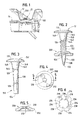
- an improved fastener 10 comprising a steel pin 100 in an improved form to be later described and a steel washer 200 in an improved form to be later described and constituting a preferred embodiment of this invention is useful for fastening a steel decking member 12, which is made from thin sheet steel oftentimes, to a steel bar joist 14.
- the decking member 12 is regarded as a workpiece
- the bar joist 14 is regarded as a substrate.
- the fastener 10 is shown in Figure 2, as assembled from the pin 100 and the washer 200, before the fastener 10 is driven.
- the fastener 10 can be forcibly driven by a fastener-driving tool, such as a powder-actuated tool, as exemplified by the powder-actuated, nosepiece-equipped, fastener-driving tool disclosed in U.S. Patents No. 5,193,729, No. 5,199,506, and No. 5,199,625. If such a tool is used, the fastener 10 is sized to be axially guided in its nosepiece, in a manner to be later described.
- a fastener-driving tool such as a powder-actuated tool, as exemplified by the powder-actuated, nosepiece-equipped, fastener-driving tool disclosed in U.S. Patents No. 5,193,729, No. 5,199,506, and No. 5,199,625. If such a tool is used, the fastener 10 is sized to be axially guided in its nosepiece, in a manner to be later described.
- the fastener 10 can be forcibly driven by a powder-actuated, fastener-driving tool, as exemplified by the powder-actuated, muzzle-equipped, fastener-driving tool disclosed in U.S. Patent No. 4,824,003. If such a tool is used, the fastener 10 is sized to enable the fastener 10 to be muzzle-loaded, in a manner disclosed therein.
- the steel pin 100 comprises a head 110, a shank 120, a point 130, and a transition zone 140 between the shank 120 and the head 110.
- the washer 200 is carried on the shank 120, in axially spaced relation to the head 110, and is movable toward the head 110 when the fastener 10 is driven forcibly through the decking member 12, into the bar joist 14, so that the washer 200 bears against the decking member 12.
- the tapered shank 120 of the steel pin 100 defines a conical angle (total taper), preferably in a range from about 2° to about 4°, and has a knurled surface 122, a smaller end 124, and a larger end 126.
- the smaller end 124 has a diameter smaller than the initial diameter of the predetermined length of carbon steel wire, preferably being about 0.6 times the initial diameter thereof.
- the larger end 126 has a diameter about 0.7 times the initial diameter of the predetermined length of carbon steel wire.
- the point 130 Being joined unitarily to the smaller end 124 of the tapered shank 120, the point 130 has a tip 132 and conforms except at the tip 132, which is rounded, substantially to a tangent ogive, which is tangent to the tapered shank 120.
- the transition zone 140 has a tapered portion 142 defining a comparatively larger conical angle, preferably a conical angle (total taper) of about 40°.
- the tapered portion 142 has a smaller end 144 joined unitarily to the larger end 126 of the tapered shank 120.
- the tapered portion 142 has a larger end 146 joined unitarily to the head 110, via a circumferential fillet 148, which is regarded as an integral part of the transition zone 140.
- the larger end 146 of the tapered portion of the transition zone has a diameter larger than the initial diameter of the predetermined length of carbon steel wire, preferably about 1.1 times the initial diameter thereof.
- the axial predetermined length of the transition zone 140 which includes the circumferential fillet 148, is less than about one half of the axial length of the tapered shank 120. It is convenient next to describe the material used to make the steel pin 100.
- the steel pin 100 is made from a predetermined length of carbon steel wire, which has a carbon content in a range from about the carbon content of AISI C 1038 steel, which has a carbon content from 0.35 percent to 0.38 percent, to about the carbon content of AISI C 1065 steel, which has a carbon content from 0.60 percent to 0.70 percent.
- a high-manganese carbon steel having a carbon content in a similar range such as AISI C 1062 high-manganese carbon steel, can be alternatively used.
- a predetermined length of AISI C 1062 steel wire is used, which has an initial diameter of about 0.208 inch.
- a lower core hardness for the pin may be used, so that a lower carbon wire may be used to create the pin.
- a more aggressive knurl may be preferred in this application, possibly a knurl with a slight helix.
- the steel pin 100 has novel proportions, which may be conveniently referenced to the initial diameter of the predetermined length of carbon steel wire used to make the pin 100.
- the head 110 has an outer diameter at least about 2.6 times greater than the initial diameter of the predetermined length of carbon steel wire.
- the tapered shank 120 has a larger end 126, which has a diameter about 0.7 times the initial diameter of the predetermined length of carbon steel wire, and the larger end of the tapered portion of the transition zone has a diameter about 1.1 times the initial diameter of the predetermined length of carbon steel wire.
- an initial step which is a forming step that may be also called a heading step and which is performed with conventional head-forming equipment for forming heads on pins or screws
- the predetermined length of carbon steel wire is formed so as to form an intermediate part 150, which is elongate and has a headed end 152 and an opposite end 154.
- Suitable head-forming equipment is available commercially from National Machinery Company of Tiffin, Ohio, under Model 56.
- the intermediate part 150 has the head 110, which is formed on the headed end 152, the shank 120, which is tapered but not yet knurled, the transition zone 140, which is disposed between the head 110 and the shank 120, and the opposite end 154.
- the point 130 is formed on the opposite end 154, and the tapered shank 120 may be knurled. It is preferred for the tapered shank 120 to be knurled.
- the intermediate part 150 is rolled between two rolling dies D 1 , D 2 , which employ the head 110 as a datum and which are configured suitably.
- Suitable form-rolling equipment is available commercially from E. W. Menn GmbH Maschinenfabrik of Hilgenbach, Germany, under Model GW 120-H.
- the intermediate part 150 is rolled so as to form the point 130 and so as to knurl the tapered shank 120, if the tapered shank 120 is to be knurled, whereby the pin 100 is formed.
- the point 130 has a tip 132 and conforms except at the tip 132, which is rounded, substantially to a tangent ogive, which is tangent to the tapered, knurled shank 120.
- a fragment 156 of the pointed end 154 is removed at the end of the die travel. It has been found that relatively long dies are preferable so that the movement of material in the pin is slow and the point of the pin is not overheated, and thus over work-hardened, whereby a uniform, smooth surface results, without laps or seams.
- the pin 100 is austempered so as to have a surface hardness not greater than about Rockwell C 48, or not greater than about Rockwell C 52 if the tapered shank 120 is not knurled, and a core hardness in a range from about Rockwell C 48 to about Rockwell C 58.
- Suitable heat treating equipment is available commercially from numerous sources.
- the pin 100 is decarburized in a conventional manner, after the rolling step, before the austempering step.
- the steel washer 200 is stamped from a sheet of carbon steel, such as AISI C 1038 steel, which is preferred. Being annular, the washer 200 has an annular periphery 202 and a central aperture 210, which has a margin 212 with a novel configuration. The washer 200 is solid between the annular periphery 202 and the margin 212 of the central aperture 210.
- the margin 212 of the central aperture 210 defines four pin-engaging protrusions 214, which have concave pin-engaging surfaces 216, which are similar to one another, and which are spaced angularly and regularly from one another by four similar recesses 218.
- each pin-engaging surface 216 conforms essentially to a section of an imaginary cylinder of a given diameter.
- Each recess 218 conforms essentially to a section of an imaginary cylinder of a larger diameter.
- the pin-engaging surfaces 216 encompass a minor portion of a complete cylinder. As shown, in the preferred mode for carrying out this invention, each pin-engaging surface 216 encompasses about 30°, which is one twelfth of a complete cylinder. Collectively, in the preferred mode for carrying out this invention, the pin-engaging surfaces 216 encompass about one third of a complete cylinder.
- the annular periphery 202 of the washer 200 has an outer diameter equal approximately to the outer diameter of the head 110 of the pin 100. Further, the central aperture 210 of the washer 200 enables the washer 200 to be tightly fitted over the tapered shank 120 of the pin 100, near the smaller end 124 of the tapered shank 120, when the fastener 10 is assembled. Thus, there is sufficient contact area that when the fastener 10 is driven by a powder-actuated tool or an equivalent tool and is accelerated, the washer 200 does not move significantly along the tapered shank 120 but stays near the point 130. Being spaced axially, the washer 200 and the head 100 of the pin guide the fastener 10 without permitting the fastener 10 to tumble in the nosepiece of a nosepiece-equipped, fastener-driving tool, as discussed above.
- the washer 200 when the fastener 10 is driven, the washer 200 is arranged to be forcibly moved along the tapered shank 120, toward the larger end 126 of the tapered shank 120, when the washer 200 engages a workpiece or a substrate. Because the pin-engaging surfaces 214 of the washer 200 encompass about one third of a complete cylinder, the pin-engaging surfaces 214 limit potential damage to the knurled surface 122 of the tapered shank 120 of the pin 100 when the washer 200 is moved along the tapered shank 120, toward the larger end 126 of the tapered shank 120.
Landscapes
- Engineering & Computer Science (AREA)
- General Engineering & Computer Science (AREA)
- Mechanical Engineering (AREA)
- Insertion Pins And Rivets (AREA)
- Joining Of Building Structures In Genera (AREA)
- Heat Treatment Of Articles (AREA)
- Slide Fasteners, Snap Fasteners, And Hook Fasteners (AREA)
- Portable Nailing Machines And Staplers (AREA)
- Mechanical Coupling Of Light Guides (AREA)
- Wire Processing (AREA)
Applications Claiming Priority (2)
| Application Number | Priority Date | Filing Date | Title |
|---|---|---|---|
| US08/994,521 US6171042B1 (en) | 1997-12-19 | 1997-12-19 | Hardened steel pin, pin and washer fastener, washer for fastener, and pin-making method |
| US994521 | 1997-12-19 |
Publications (2)
| Publication Number | Publication Date |
|---|---|
| EP0926361A1 EP0926361A1 (en) | 1999-06-30 |
| EP0926361B1 true EP0926361B1 (en) | 2003-05-28 |
Family
ID=25540752
Family Applications (1)
| Application Number | Title | Priority Date | Filing Date |
|---|---|---|---|
| EP98403215A Expired - Lifetime EP0926361B1 (en) | 1997-12-19 | 1998-12-18 | Pin, pin and washer fastener, washer for the fastener and pin-making method |
Country Status (9)
| Country | Link |
|---|---|
| US (3) | US6171042B1 (enExample) |
| EP (1) | EP0926361B1 (enExample) |
| JP (1) | JP4447683B2 (enExample) |
| AT (1) | ATE241764T1 (enExample) |
| AU (1) | AU711821B2 (enExample) |
| BR (1) | BR9804726A (enExample) |
| CA (1) | CA2254250C (enExample) |
| DE (1) | DE69815041T2 (enExample) |
| ES (1) | ES2200293T3 (enExample) |
Cited By (1)
| Publication number | Priority date | Publication date | Assignee | Title |
|---|---|---|---|---|
| US7374384B2 (en) | 2005-07-26 | 2008-05-20 | Stanley Fastening Systems, L.P. | Fasteners for securing pallet members together |
Families Citing this family (33)
| Publication number | Priority date | Publication date | Assignee | Title |
|---|---|---|---|---|
| DE10119800A1 (de) * | 2001-04-23 | 2002-10-24 | Hilti Ag | Befestigungselement |
| DE10119799A1 (de) * | 2001-04-23 | 2002-10-24 | Hilti Ag | Nagelförmiges Befestigungselement |
| US20030070736A1 (en) * | 2001-10-12 | 2003-04-17 | Borg Warner Inc. | High-hardness, highly ductile ferrous articles |
| KR100463086B1 (ko) * | 2002-01-12 | 2004-12-23 | 금성볼트공업 주식회사 | 목재 고정용 핀의 제조방법 |
| DE10205031B4 (de) * | 2002-02-07 | 2004-01-08 | Hilti Ag | Verfahren zum Herstellen eines, mittels eines Setzgerätes eintreibbaren Befestigungselementes sowie ein Setzgerät hierfür und ein Befestigungselement |
| US6739567B1 (en) * | 2002-10-11 | 2004-05-25 | Pacific Cascade Parking Equipment Corporation | Separable magnetic attachment assembly |
| US6872042B2 (en) * | 2003-05-08 | 2005-03-29 | Illinois Tool Works Inc. | Knurled fastener with cutting edges and removable head |
| DE10328197B3 (de) * | 2003-06-24 | 2004-04-08 | Hilti Ag | Befestigungselement |
| USD539638S1 (en) | 2004-03-25 | 2007-04-03 | Senior Industries, Inc. | Baseboard clip |
| US20050269756A1 (en) * | 2004-06-04 | 2005-12-08 | Robin Stevenson | Reconfigurable clamp for a flexible manufacturing system |
| US20050269757A1 (en) * | 2004-06-04 | 2005-12-08 | Robin Stevenson | Reconfigurable clamp for a flexible manufacturing system |
| US7207761B2 (en) * | 2004-07-26 | 2007-04-24 | Illinois Tool Works Inc. | Pin fastener for achieving metal-to-metal connections |
| AU2005333514B8 (en) | 2004-07-26 | 2009-04-23 | Illinois Tool Works Inc. | Pin fastener for achieving metal-to-metal connections |
| DE102004040701B3 (de) * | 2004-08-23 | 2005-07-14 | Hilti Ag | Befestigungselement |
| DE102004059638B3 (de) * | 2004-12-10 | 2006-08-03 | Hilti Ag | Vorrichtung und Verfahren zum Erzeugen einer Profilierung an einem Befestigungselement |
| JP4683932B2 (ja) * | 2005-01-14 | 2011-05-18 | 日本パワーファスニング株式会社 | 連結ピン |
| DE102006002238C5 (de) * | 2006-01-17 | 2019-02-28 | Böllhoff Verbindungstechnik GmbH | Verfahren zum Herstellen einer Nagelverbindung sowie Nagel hierfür |
| US20070217889A1 (en) * | 2006-03-14 | 2007-09-20 | Kevin Greene | Pin fastener having a sharp point |
| JP4739118B2 (ja) * | 2006-05-31 | 2011-08-03 | 日本パワーファスニング株式会社 | 打ち込み式連結ファスナー |
| WO2008034167A1 (en) * | 2006-09-20 | 2008-03-27 | Itw Construction Systems Australia Pty Ltd | A fastening pin and washer used with a fastening tool to secure a layer of insulation to a substrate |
| JP2008115995A (ja) * | 2006-11-07 | 2008-05-22 | Max Co Ltd | 段付きコンクリートピン |
| US20080172979A1 (en) * | 2007-01-19 | 2008-07-24 | Wilson Eric J | Reinforcing bar splice with cutting edge bolts |
| US20080247843A1 (en) * | 2007-03-26 | 2008-10-09 | Shluzas Robert J | Fastening system |
| JP5190885B2 (ja) * | 2008-12-02 | 2013-04-24 | 新日本ファスナー工業株式会社 | ローレットピンの成形方法及びその装置 |
| EP2438314B1 (en) * | 2009-06-04 | 2014-03-05 | Raimund Beck Nageltechnik GmbH | Screw nail for connecting plane material combinations in dry construction |
| US8449237B2 (en) * | 2010-01-29 | 2013-05-28 | Black & Decker Inc. | Knurled pin fastener and method of forming a knurled pin fastener |
| JP5779904B2 (ja) * | 2011-02-24 | 2015-09-16 | マックス株式会社 | 硬質の被打ち込み部材用締結ピン及びその成形方法 |
| US9945403B2 (en) * | 2013-03-04 | 2018-04-17 | Paul Fabis | Rigid foam board installation clip |
| US10443230B2 (en) * | 2016-02-10 | 2019-10-15 | Black & Decker, Inc. | Composite deck fastener |
| DE102018103205A1 (de) * | 2018-02-13 | 2019-08-14 | Ejot Gmbh & Co. Kg | Fügeelement |
| DE102018103326A1 (de) * | 2018-02-14 | 2019-08-14 | Ejot Gmbh & Co. Kg | Verbindungselement |
| US11047139B2 (en) | 2019-07-09 | 2021-06-29 | Schluter Systems L.P. | Veneer profile with fastening feature and related methods |
| DE102023123657A1 (de) | 2023-09-01 | 2025-03-06 | Technische Universität Ilmenau, Körperschaft des öffentlichen Rechts | VERFAHREN ZUR HERSTELLUNG VON RÜHRREIBSCHWEIßSTIFTEN DURCH UMFORMUNG MITTELS EINES WALZPROZESSES |
Family Cites Families (61)
| Publication number | Priority date | Publication date | Assignee | Title |
|---|---|---|---|---|
| US368688A (en) | 1887-08-23 | rogers | ||
| US387184A (en) | 1888-07-31 | rogers | ||
| DE1074519B (de) | 1960-01-28 | Schulz Me« mann Walter (RhId) | Verfahren zum Einschießen von Bolzen in aus Metall insbesondere aus Stahl bestehende Aut nahmewerkstucke und Setzbolzen zur Durchfuhrung des Verfahrens | |
| US328951A (en) | 1885-10-27 | Screw-swaging machine | ||
| US1273441A (en) | 1917-06-19 | 1918-07-23 | H H Mayhew Company | Method or process of nurling. |
| US1547162A (en) * | 1919-08-15 | 1925-07-28 | Kellogg Switchboard & Supply | Washer |
| US1913143A (en) | 1931-02-24 | 1933-06-06 | Peter L Robertson | Means for roll-threading and pointing screws |
| US2165007A (en) | 1933-01-14 | 1939-07-04 | Rosenberg Heyman | Art of forming ribbed fasteners |
| US2191771A (en) | 1937-09-16 | 1940-02-27 | Illinois Tool Works | Fastener |
| US2291751A (en) | 1940-05-02 | 1942-08-04 | Parker Kalon Corp | Manufacture of fastener devices |
| US2347350A (en) * | 1942-05-12 | 1944-04-25 | Aluminum Ind Inc | Knurling machine |
| US2342910A (en) * | 1942-08-04 | 1944-02-29 | Tinnerman Products Inc | Fastening device |
| US2751808A (en) * | 1953-05-04 | 1956-06-26 | Remington Arms Co Inc | Explosively driven stud having polished point |
| FR1081475A (fr) | 1953-07-21 | 1954-12-20 | Ile D Etude De Procedes De Sce | Bourre pour les projectiles des pistolets tamponneurs et goujonneurs |
| DE1181139B (de) * | 1958-05-24 | 1964-11-05 | Impex Essen Vertrieb | Bolzen zum Einschiessen oder Eintreiben in metallische Bauteile |
| US3019677A (en) | 1959-05-27 | 1962-02-06 | Italo J Cermatori | Rolling dies for threading, pointing and finishing screws |
| US3154075A (en) | 1960-11-02 | 1964-10-27 | Norwich Pharma Co | Vaginal applicator |
| US3154975A (en) | 1961-01-26 | 1964-11-03 | Rca Corp | Apparatus for pointing and severing wires or pins |
| US3137195A (en) * | 1961-11-20 | 1964-06-16 | American Internat Tool Corp | Centering and guiding means for metal studs |
| US3196654A (en) | 1962-06-11 | 1965-07-27 | Illinois Tool Works | Screw rolling die |
| NL292500A (enExample) | 1963-01-25 | |||
| GB1050026A (enExample) | 1963-11-06 | |||
| US3324542A (en) | 1964-12-18 | 1967-06-13 | Fur Montage Technik Anstalt | Method of fastening objects to hard material |
| US3320711A (en) * | 1965-02-16 | 1967-05-23 | Thomas B Johnson | Construction sheet and fastening means |
| US3405547A (en) | 1966-09-27 | 1968-10-15 | Reed Rolled Thread Die Co | Thread rolling die with twisted slug forming and removal surface |
| DE1575149C3 (de) | 1967-03-07 | 1980-06-26 | Hilti Ag, Schaan (Liechtenstein) | Nagel zum Eintreiben in hartes Aufnahmematerial |
| USRE26518E (en) | 1967-04-05 | 1969-01-14 | Thread and other form rolling dies | |
| AT294721B (de) | 1967-04-20 | 1971-12-10 | Hilti Ag | Bolzen, bzw. Nagel für pulverkraftbetriebene Bolzensetzgeräte zum Setzen in metallische Werkstoffe |
| US3538739A (en) | 1968-04-01 | 1970-11-10 | Reed Rolled Thread Die Co | Thread rolling die with cylindrical slug forming and removal surface |
| GB1269117A (en) | 1968-07-18 | 1972-04-06 | Rotary Profile Anstalt | Improvements in or relating to rolling headed articles |
| AU448868B2 (en) * | 1971-07-26 | 1974-05-14 | Ramsey Fasteners (Australia) Pty. Ltd | Fastener assembly |
| US3789643A (en) | 1972-02-10 | 1974-02-05 | Reed Rolled Thread Die Co | Double angle cutoff die and method for rolling screws |
| DE2237528C2 (de) | 1972-07-31 | 1983-12-08 | Hilti AG, 9494 Schaan | Nagel für pulverkraftbetriebene Setzgeräte |
| US3858478A (en) | 1972-08-24 | 1975-01-07 | Jr John J Boudreau | Concrete fastener |
| US3828604A (en) | 1973-06-08 | 1974-08-13 | Illinois Tool Works | Method and apparatus for forming tips of screws |
| FR2374143A1 (fr) * | 1976-12-17 | 1978-07-13 | Alsetex | Dispositif pyrotechnique pour la fixation d'un objet sur une paroi, notamment metallique |
| US4829800A (en) * | 1983-01-17 | 1989-05-16 | Anderson-Cook, Inc. | Method and apparatus for cold sizing a round workpiece having multiple diameters |
| US4621963A (en) * | 1984-03-26 | 1986-11-11 | Elco Industries, Inc. | Fastener for roof assemblies and the like |
| US4612501A (en) * | 1984-07-26 | 1986-09-16 | General Motors Corporation | Self-adjusting magnetic sensor |
| GB8507191D0 (en) * | 1985-03-20 | 1985-04-24 | Cladcolor Profiling Ltd | Support system |
| FR2608493B1 (fr) | 1986-12-23 | 1994-09-02 | Prospection & Inventions | Appareil de scellement a tir indirect |
| DE3707424A1 (de) | 1987-03-07 | 1988-09-15 | Hilti Ag | Befestigungselement mit nagel und huelse |
| DE3743049A1 (de) | 1987-12-18 | 1989-06-29 | Hilti Ag | Nagel mit stauchbarer huelse |
| BR8800864A (pt) | 1988-02-29 | 1989-09-26 | Amp Do Brasil Conectores Eletr | Aparelhos e processo para a fabricacao de pinos eletricos |
| DE3813245A1 (de) | 1988-04-20 | 1989-11-02 | Hilti Ag | Befestigungselement mit fuehrungsrondelle |
| US4881395A (en) | 1988-06-21 | 1989-11-21 | Yugen Kaisha Shinjo Seisakusho | Process and apparatus for fabricating stepped nails |
| DE3843391A1 (de) | 1988-12-23 | 1990-06-28 | Hilti Ag | Befestigungselement |
| US4936071A (en) * | 1989-09-05 | 1990-06-26 | Bridgestone/Firestone Inc. | Metal roof reroofing system and method |
| DE3931833A1 (de) | 1989-09-23 | 1991-04-04 | Hilti Ag | Befestigungselement zum befestigen von isolationsplatten |
| US5038529A (en) * | 1990-03-29 | 1991-08-13 | Conley's Manufacturing & Sales | Roof support structure |
| US5193729A (en) | 1991-09-26 | 1993-03-16 | Illinois Tool Works Inc. | Fastener-driving tool assembly with improved fastener-loading features |
| US5199625A (en) | 1991-09-26 | 1993-04-06 | Illinois Tool Works Inc. | Fastener-driving tool assembly with improved fastener-loading features |
| US5199506A (en) | 1991-09-26 | 1993-04-06 | Illinois Tool Works Inc. | Fastener-driving tool assembly with improved fastener-loading features |
| DE4135500A1 (de) | 1991-10-28 | 1993-04-29 | Hilti Ag | Nagel mit huelse und rondelle |
| DE4139653A1 (de) | 1991-12-02 | 1993-08-26 | Hilti Ag | Korrosionsbestaendiger nagel zum eintreiben in harte werkstoffe |
| US5292216A (en) * | 1993-03-12 | 1994-03-08 | Illinois Tool Works Inc. | Fastener assembly for a power actuated tool |
| DE4332355A1 (de) * | 1993-09-23 | 1995-03-30 | Hilti Ag | Befestigungselement |
| AU683745B2 (en) * | 1994-06-20 | 1997-11-20 | Illinois Tool Works Inc. | Steel pin and method for its manufacturing |
| US5851153A (en) * | 1994-06-20 | 1998-12-22 | Illinois Tool Works Inc. | Method for steel pin manufacture |
| DE19542949A1 (de) * | 1995-11-17 | 1997-07-17 | Hilti Ag | Bolzen zum Eintreiben in harte Aufnahmewerkstoffe |
| US6017274A (en) * | 1997-09-02 | 2000-01-25 | Automotive Racing Products, Inc. | Method of forming a fastener |
-
1997
- 1997-12-19 US US08/994,521 patent/US6171042B1/en not_active Expired - Fee Related
-
1998
- 1998-11-18 CA CA002254250A patent/CA2254250C/en not_active Expired - Fee Related
- 1998-11-20 BR BR9804726-4A patent/BR9804726A/pt not_active IP Right Cessation
- 1998-12-09 AU AU96971/98A patent/AU711821B2/en not_active Ceased
- 1998-12-18 AT AT98403215T patent/ATE241764T1/de not_active IP Right Cessation
- 1998-12-18 EP EP98403215A patent/EP0926361B1/en not_active Expired - Lifetime
- 1998-12-18 DE DE69815041T patent/DE69815041T2/de not_active Expired - Lifetime
- 1998-12-18 ES ES98403215T patent/ES2200293T3/es not_active Expired - Lifetime
- 1998-12-21 JP JP36325898A patent/JP4447683B2/ja not_active Expired - Fee Related
-
1999
- 1999-07-29 US US09/363,021 patent/US6203442B1/en not_active Expired - Fee Related
-
2000
- 2000-02-10 US US09/499,521 patent/US6305065B1/en not_active Expired - Lifetime
Cited By (1)
| Publication number | Priority date | Publication date | Assignee | Title |
|---|---|---|---|---|
| US7374384B2 (en) | 2005-07-26 | 2008-05-20 | Stanley Fastening Systems, L.P. | Fasteners for securing pallet members together |
Also Published As
| Publication number | Publication date |
|---|---|
| AU9697198A (en) | 1999-07-08 |
| JP4447683B2 (ja) | 2010-04-07 |
| JPH11257315A (ja) | 1999-09-21 |
| CA2254250A1 (en) | 1999-06-19 |
| ES2200293T3 (es) | 2004-03-01 |
| DE69815041T2 (de) | 2003-11-27 |
| CA2254250C (en) | 2003-01-21 |
| DE69815041D1 (de) | 2003-07-03 |
| US6171042B1 (en) | 2001-01-09 |
| EP0926361A1 (en) | 1999-06-30 |
| US6305065B1 (en) | 2001-10-23 |
| US6203442B1 (en) | 2001-03-20 |
| ATE241764T1 (de) | 2003-06-15 |
| BR9804726A (pt) | 1999-11-03 |
| AU711821B2 (en) | 1999-10-21 |
Similar Documents
| Publication | Publication Date | Title |
|---|---|---|
| EP0926361B1 (en) | Pin, pin and washer fastener, washer for the fastener and pin-making method | |
| JPH11257315A5 (enExample) | ||
| US5642974A (en) | Fastener and building assembly comprising workpiece, substrate, and fastener | |
| JP4114908B2 (ja) | ブラインド締結具 | |
| KR100959296B1 (ko) | 셀프 태핑 나사, 블랭크, 그 제조를 위한 방법 및 금형, 그리고 얇은 소재들을 결합하기 위한 방법 | |
| US4531871A (en) | Multigrip fastener | |
| JP2014043951A (ja) | ファスナ及びその装着方法 | |
| JP4051345B2 (ja) | ブラインド側ヘッドにクランプ支持しロックする部分を有するブラインドファスナー | |
| CN101589238B (zh) | 具有凹槽的紧固件 | |
| US4778318A (en) | Self-locking blind fastener | |
| CN101360920B (zh) | 低模压负载紧固系统及方法 | |
| JPS63254212A (ja) | 自己閉塞のブラインドリベット | |
| CA2347974A1 (en) | Lightweight threaded fastener and thread rolling die | |
| GB2444420A (en) | Low swage load fastening system and method | |
| JP2667790B2 (ja) | ブラインドファスナ、ブラインドファスナの製造方法およびブラインドファスナ製造用加工装置 | |
| US5733086A (en) | Combined rivet/nail components and methods for using same | |
| US3978758A (en) | Bolt and process of forming same | |
| CA2049566C (en) | Wire nail, strip of collated wire nails, and related apparatus | |
| US4630463A (en) | Rivet driving die and method | |
| US5860866A (en) | Steel pin and method for its manufacture | |
| AU719346B2 (en) | Hardened steel pin, pin and washer fastener, washer for fastener, and pin-making method | |
| GB1604504A (en) | Blind fastener | |
| US4263834A (en) | Rivet and construction thereof | |
| NZ500767A (en) | Making a steel pin for axial, non-rotational penetration of a steel, concrete or masonry substrate | |
| RU2095185C1 (ru) | Способ изготовления шаровых пальцевх |
Legal Events
| Date | Code | Title | Description |
|---|---|---|---|
| PUAI | Public reference made under article 153(3) epc to a published international application that has entered the european phase |
Free format text: ORIGINAL CODE: 0009012 |
|
| AK | Designated contracting states |
Kind code of ref document: A1 Designated state(s): AT BE CH CY DE DK ES FI FR GB GR IE IT LI LU NL PT SE |
|
| AX | Request for extension of the european patent |
Free format text: AL;LT;LV;MK;RO;SI |
|
| 17P | Request for examination filed |
Effective date: 19991221 |
|
| AKX | Designation fees paid |
Free format text: AT BE CH CY DE DK ES FI FR GB GR IE IT LI LU NL PT SE |
|
| 17Q | First examination report despatched |
Effective date: 20020507 |
|
| GRAH | Despatch of communication of intention to grant a patent |
Free format text: ORIGINAL CODE: EPIDOS IGRA |
|
| GRAH | Despatch of communication of intention to grant a patent |
Free format text: ORIGINAL CODE: EPIDOS IGRA |
|
| GRAA | (expected) grant |
Free format text: ORIGINAL CODE: 0009210 |
|
| AK | Designated contracting states |
Designated state(s): AT BE CH CY DE DK ES FI FR GB GR IE IT LI LU NL PT SE |
|
| PG25 | Lapsed in a contracting state [announced via postgrant information from national office to epo] |
Ref country code: LI Free format text: LAPSE BECAUSE OF FAILURE TO SUBMIT A TRANSLATION OF THE DESCRIPTION OR TO PAY THE FEE WITHIN THE PRESCRIBED TIME-LIMIT Effective date: 20030528 Ref country code: IT Free format text: LAPSE BECAUSE OF FAILURE TO SUBMIT A TRANSLATION OF THE DESCRIPTION OR TO PAY THE FEE WITHIN THE PRESCRIBED TIME-LIMIT;WARNING: LAPSES OF ITALIAN PATENTS WITH EFFECTIVE DATE BEFORE 2007 MAY HAVE OCCURRED AT ANY TIME BEFORE 2007. THE CORRECT EFFECTIVE DATE MAY BE DIFFERENT FROM THE ONE RECORDED. Effective date: 20030528 Ref country code: FI Free format text: LAPSE BECAUSE OF FAILURE TO SUBMIT A TRANSLATION OF THE DESCRIPTION OR TO PAY THE FEE WITHIN THE PRESCRIBED TIME-LIMIT Effective date: 20030528 Ref country code: CH Free format text: LAPSE BECAUSE OF FAILURE TO SUBMIT A TRANSLATION OF THE DESCRIPTION OR TO PAY THE FEE WITHIN THE PRESCRIBED TIME-LIMIT Effective date: 20030528 Ref country code: AT Free format text: LAPSE BECAUSE OF FAILURE TO SUBMIT A TRANSLATION OF THE DESCRIPTION OR TO PAY THE FEE WITHIN THE PRESCRIBED TIME-LIMIT Effective date: 20030528 |
|
| REG | Reference to a national code |
Ref country code: GB Ref legal event code: FG4D |
|
| REG | Reference to a national code |
Ref country code: CH Ref legal event code: EP |
|
| REG | Reference to a national code |
Ref country code: IE Ref legal event code: FG4D |
|
| REF | Corresponds to: |
Ref document number: 69815041 Country of ref document: DE Date of ref document: 20030703 Kind code of ref document: P |
|
| PG25 | Lapsed in a contracting state [announced via postgrant information from national office to epo] |
Ref country code: SE Free format text: LAPSE BECAUSE OF FAILURE TO SUBMIT A TRANSLATION OF THE DESCRIPTION OR TO PAY THE FEE WITHIN THE PRESCRIBED TIME-LIMIT Effective date: 20030828 Ref country code: PT Free format text: LAPSE BECAUSE OF FAILURE TO SUBMIT A TRANSLATION OF THE DESCRIPTION OR TO PAY THE FEE WITHIN THE PRESCRIBED TIME-LIMIT Effective date: 20030828 Ref country code: GR Free format text: LAPSE BECAUSE OF FAILURE TO SUBMIT A TRANSLATION OF THE DESCRIPTION OR TO PAY THE FEE WITHIN THE PRESCRIBED TIME-LIMIT Effective date: 20030828 Ref country code: DK Free format text: LAPSE BECAUSE OF FAILURE TO SUBMIT A TRANSLATION OF THE DESCRIPTION OR TO PAY THE FEE WITHIN THE PRESCRIBED TIME-LIMIT Effective date: 20030828 |
|
| REG | Reference to a national code |
Ref country code: CH Ref legal event code: PL |
|
| PG25 | Lapsed in a contracting state [announced via postgrant information from national office to epo] |
Ref country code: LU Free format text: LAPSE BECAUSE OF NON-PAYMENT OF DUE FEES Effective date: 20031218 Ref country code: IE Free format text: LAPSE BECAUSE OF NON-PAYMENT OF DUE FEES Effective date: 20031218 Ref country code: CY Free format text: LAPSE BECAUSE OF FAILURE TO SUBMIT A TRANSLATION OF THE DESCRIPTION OR TO PAY THE FEE WITHIN THE PRESCRIBED TIME-LIMIT Effective date: 20031218 |
|
| REG | Reference to a national code |
Ref country code: ES Ref legal event code: FG2A Ref document number: 2200293 Country of ref document: ES Kind code of ref document: T3 |
|
| ET | Fr: translation filed | ||
| PLBE | No opposition filed within time limit |
Free format text: ORIGINAL CODE: 0009261 |
|
| STAA | Information on the status of an ep patent application or granted ep patent |
Free format text: STATUS: NO OPPOSITION FILED WITHIN TIME LIMIT |
|
| 26N | No opposition filed |
Effective date: 20040302 |
|
| REG | Reference to a national code |
Ref country code: IE Ref legal event code: MM4A |
|
| PGFP | Annual fee paid to national office [announced via postgrant information from national office to epo] |
Ref country code: ES Payment date: 20050110 Year of fee payment: 7 |
|
| PG25 | Lapsed in a contracting state [announced via postgrant information from national office to epo] |
Ref country code: ES Free format text: LAPSE BECAUSE OF NON-PAYMENT OF DUE FEES Effective date: 20051219 |
|
| REG | Reference to a national code |
Ref country code: ES Ref legal event code: FD2A Effective date: 20051219 |
|
| PGFP | Annual fee paid to national office [announced via postgrant information from national office to epo] |
Ref country code: GB Payment date: 20071227 Year of fee payment: 10 |
|
| GBPC | Gb: european patent ceased through non-payment of renewal fee |
Effective date: 20081218 |
|
| PG25 | Lapsed in a contracting state [announced via postgrant information from national office to epo] |
Ref country code: GB Free format text: LAPSE BECAUSE OF NON-PAYMENT OF DUE FEES Effective date: 20081218 |
|
| PGFP | Annual fee paid to national office [announced via postgrant information from national office to epo] |
Ref country code: NL Payment date: 20091224 Year of fee payment: 12 |
|
| PGFP | Annual fee paid to national office [announced via postgrant information from national office to epo] |
Ref country code: DE Payment date: 20091230 Year of fee payment: 12 Ref country code: BE Payment date: 20100212 Year of fee payment: 12 |
|
| BERE | Be: lapsed |
Owner name: ILLINOIS *TOOL WORKS INC. Effective date: 20101231 |
|
| REG | Reference to a national code |
Ref country code: NL Ref legal event code: V1 Effective date: 20110701 |
|
| PG25 | Lapsed in a contracting state [announced via postgrant information from national office to epo] |
Ref country code: BE Free format text: LAPSE BECAUSE OF NON-PAYMENT OF DUE FEES Effective date: 20101231 |
|
| PG25 | Lapsed in a contracting state [announced via postgrant information from national office to epo] |
Ref country code: DE Free format text: LAPSE BECAUSE OF NON-PAYMENT OF DUE FEES Effective date: 20110701 |
|
| REG | Reference to a national code |
Ref country code: DE Ref legal event code: R119 Ref document number: 69815041 Country of ref document: DE Effective date: 20110701 |
|
| PG25 | Lapsed in a contracting state [announced via postgrant information from national office to epo] |
Ref country code: NL Free format text: LAPSE BECAUSE OF NON-PAYMENT OF DUE FEES Effective date: 20110701 |
|
| PGFP | Annual fee paid to national office [announced via postgrant information from national office to epo] |
Ref country code: FR Payment date: 20130110 Year of fee payment: 15 |
|
| REG | Reference to a national code |
Ref country code: FR Ref legal event code: ST Effective date: 20140829 |
|
| PG25 | Lapsed in a contracting state [announced via postgrant information from national office to epo] |
Ref country code: FR Free format text: LAPSE BECAUSE OF NON-PAYMENT OF DUE FEES Effective date: 20131231 |