EP0925997A2 - Siège de sécurité pour véhicules - Google Patents
Siège de sécurité pour véhicules Download PDFInfo
- Publication number
- EP0925997A2 EP0925997A2 EP98250445A EP98250445A EP0925997A2 EP 0925997 A2 EP0925997 A2 EP 0925997A2 EP 98250445 A EP98250445 A EP 98250445A EP 98250445 A EP98250445 A EP 98250445A EP 0925997 A2 EP0925997 A2 EP 0925997A2
- Authority
- EP
- European Patent Office
- Prior art keywords
- vehicle seat
- seat according
- safety vehicle
- reservoir
- occupant
- Prior art date
- Legal status (The legal status is an assumption and is not a legal conclusion. Google has not performed a legal analysis and makes no representation as to the accuracy of the status listed.)
- Withdrawn
Links
Images


Classifications
-
- B—PERFORMING OPERATIONS; TRANSPORTING
- B60—VEHICLES IN GENERAL
- B60R—VEHICLES, VEHICLE FITTINGS, OR VEHICLE PARTS, NOT OTHERWISE PROVIDED FOR
- B60R21/00—Arrangements or fittings on vehicles for protecting or preventing injuries to occupants or pedestrians in case of accidents or other traffic risks
- B60R21/02—Occupant safety arrangements or fittings, e.g. crash pads
- B60R21/16—Inflatable occupant restraints or confinements designed to inflate upon impact or impending impact, e.g. air bags
- B60R21/20—Arrangements for storing inflatable members in their non-use or deflated condition; Arrangement or mounting of air bag modules or components
- B60R21/207—Arrangements for storing inflatable members in their non-use or deflated condition; Arrangement or mounting of air bag modules or components in vehicle seats
-
- B—PERFORMING OPERATIONS; TRANSPORTING
- B60—VEHICLES IN GENERAL
- B60N—SEATS SPECIALLY ADAPTED FOR VEHICLES; VEHICLE PASSENGER ACCOMMODATION NOT OTHERWISE PROVIDED FOR
- B60N2/00—Seats specially adapted for vehicles; Arrangement or mounting of seats in vehicles
- B60N2/24—Seats specially adapted for vehicles; Arrangement or mounting of seats in vehicles for particular purposes or particular vehicles
- B60N2/42—Seats specially adapted for vehicles; Arrangement or mounting of seats in vehicles for particular purposes or particular vehicles the seat constructed to protect the occupant from the effect of abnormal g-forces, e.g. crash or safety seats
- B60N2/4207—Seats specially adapted for vehicles; Arrangement or mounting of seats in vehicles for particular purposes or particular vehicles the seat constructed to protect the occupant from the effect of abnormal g-forces, e.g. crash or safety seats characterised by the direction of the g-forces
- B60N2/4214—Seats specially adapted for vehicles; Arrangement or mounting of seats in vehicles for particular purposes or particular vehicles the seat constructed to protect the occupant from the effect of abnormal g-forces, e.g. crash or safety seats characterised by the direction of the g-forces longitudinal
- B60N2/4228—Seats specially adapted for vehicles; Arrangement or mounting of seats in vehicles for particular purposes or particular vehicles the seat constructed to protect the occupant from the effect of abnormal g-forces, e.g. crash or safety seats characterised by the direction of the g-forces longitudinal due to impact coming from the rear
-
- B—PERFORMING OPERATIONS; TRANSPORTING
- B60—VEHICLES IN GENERAL
- B60N—SEATS SPECIALLY ADAPTED FOR VEHICLES; VEHICLE PASSENGER ACCOMMODATION NOT OTHERWISE PROVIDED FOR
- B60N2/00—Seats specially adapted for vehicles; Arrangement or mounting of seats in vehicles
- B60N2/80—Head-rests
- B60N2/806—Head-rests movable or adjustable
- B60N2/865—Head-rests movable or adjustable providing a fore-and-aft movement with respect to the occupant's head
-
- B—PERFORMING OPERATIONS; TRANSPORTING
- B60—VEHICLES IN GENERAL
- B60N—SEATS SPECIALLY ADAPTED FOR VEHICLES; VEHICLE PASSENGER ACCOMMODATION NOT OTHERWISE PROVIDED FOR
- B60N2/00—Seats specially adapted for vehicles; Arrangement or mounting of seats in vehicles
- B60N2/80—Head-rests
- B60N2/888—Head-rests with arrangements for protecting against abnormal g-forces, e.g. by displacement of the head-rest
-
- B—PERFORMING OPERATIONS; TRANSPORTING
- B60—VEHICLES IN GENERAL
- B60R—VEHICLES, VEHICLE FITTINGS, OR VEHICLE PARTS, NOT OTHERWISE PROVIDED FOR
- B60R21/00—Arrangements or fittings on vehicles for protecting or preventing injuries to occupants or pedestrians in case of accidents or other traffic risks
- B60R21/02—Occupant safety arrangements or fittings, e.g. crash pads
- B60R21/16—Inflatable occupant restraints or confinements designed to inflate upon impact or impending impact, e.g. air bags
- B60R21/26—Inflatable occupant restraints or confinements designed to inflate upon impact or impending impact, e.g. air bags characterised by the inflation fluid source or means to control inflation fluid flow
- B60R21/26005—Inflatable occupant restraints or confinements designed to inflate upon impact or impending impact, e.g. air bags characterised by the inflation fluid source or means to control inflation fluid flow the inflation fluid being transferred to the inflatable member by the mechanical deformation of the fluid container during an impact
-
- B—PERFORMING OPERATIONS; TRANSPORTING
- B60—VEHICLES IN GENERAL
- B60R—VEHICLES, VEHICLE FITTINGS, OR VEHICLE PARTS, NOT OTHERWISE PROVIDED FOR
- B60R21/00—Arrangements or fittings on vehicles for protecting or preventing injuries to occupants or pedestrians in case of accidents or other traffic risks
- B60R2021/0002—Type of accident
- B60R2021/0011—Rear collision or recoiling bounce after frontal collision
-
- B—PERFORMING OPERATIONS; TRANSPORTING
- B60—VEHICLES IN GENERAL
- B60R—VEHICLES, VEHICLE FITTINGS, OR VEHICLE PARTS, NOT OTHERWISE PROVIDED FOR
- B60R21/00—Arrangements or fittings on vehicles for protecting or preventing injuries to occupants or pedestrians in case of accidents or other traffic risks
- B60R21/02—Occupant safety arrangements or fittings, e.g. crash pads
- B60R21/16—Inflatable occupant restraints or confinements designed to inflate upon impact or impending impact, e.g. air bags
- B60R21/20—Arrangements for storing inflatable members in their non-use or deflated condition; Arrangement or mounting of air bag modules or components
- B60R21/207—Arrangements for storing inflatable members in their non-use or deflated condition; Arrangement or mounting of air bag modules or components in vehicle seats
- B60R2021/2074—Arrangements for storing inflatable members in their non-use or deflated condition; Arrangement or mounting of air bag modules or components in vehicle seats in head rests
-
- B—PERFORMING OPERATIONS; TRANSPORTING
- B60—VEHICLES IN GENERAL
- B60R—VEHICLES, VEHICLE FITTINGS, OR VEHICLE PARTS, NOT OTHERWISE PROVIDED FOR
- B60R21/00—Arrangements or fittings on vehicles for protecting or preventing injuries to occupants or pedestrians in case of accidents or other traffic risks
- B60R21/02—Occupant safety arrangements or fittings, e.g. crash pads
- B60R21/16—Inflatable occupant restraints or confinements designed to inflate upon impact or impending impact, e.g. air bags
- B60R21/20—Arrangements for storing inflatable members in their non-use or deflated condition; Arrangement or mounting of air bag modules or components
- B60R21/215—Arrangements for storing inflatable members in their non-use or deflated condition; Arrangement or mounting of air bag modules or components characterised by the covers for the inflatable member
- B60R2021/21525—Arrangements for storing inflatable members in their non-use or deflated condition; Arrangement or mounting of air bag modules or components characterised by the covers for the inflatable member the lid being fixed on the bag, or forming part of the bag wall, or the bag itself being used as wall liner
Definitions
- the invention relates to a safety vehicle seat with a backrest and one of the backrests assigned headrest, at least the side facing the head of the occupant the headrest as a result of a crash-related load on the backrest forwards and upwards or is only moved forward and the headrest can be filled with a flowable medium Element is assigned.
- Headrests have the task to intercept the occupant's head if this is caused by a rear-end collision is thrown.
- the head travels a distance relative to the body, depending on the setting the headrest and seating position are of different lengths. The bigger this path is, the bigger is the risk of serious injury to the cervical spine.
- a gas source is located at the level of the occupant's head, which, when activated as a result of a collision, inflates the gas bag and thus the head supports. Suitable means are provided to stabilize the gas bag as it expands, that it can only expand in the direction of the occupant's head.
- a gas source gas generators are used, such as those associated with the development of airbags have become known. The activation takes place just like there with the usual pyrotechnic Means.
- a solution is known from DE 297 10 511 U1 in which a gas generator is also optional can be arranged in the backrest and a connection to that inserted in the headrest Has gas bag.
- a solution is known from US Pat. No. 5,378,043 that works on a different principle. Also the aim here is to make the movement of the headrest dependent on the intensity of the impact.
- the headrest is mounted in a lever system, with the at one end of the lever Headrests and a plate is arranged at the opposite end. The plate is in the Integrated backrest.
- the long response time of the system is disadvantageous.
- the reason for this is that the mechanics are too sluggish is. This also leads to a relatively large counterforce at the points where the force over the Back of the occupant is initiated. The headrest moves forward with a delay. The security effect is therefore small.
- the system also has the disadvantage that the triggering force is relative in the case of very strong crashes is high and the headrest is accelerated too much. This leads to a significant Force applied when the headrest hits the back of the occupant's head. Farther the mechanical elements require a relatively large amount of space. This will give the rear knee room seated passenger restricted or even at risk.
- the object of the invention is to eliminate the disadvantages mentioned above.
- the object is achieved in that at least one with the flowable in the backrest Medium-filled reservoir connected to the fillable element in the headrest is arranged and at least part of the shell of this reservoir is flexible.
- connection between the reservoir and the formed by the flowable medium element as an overflow channel.
- the overflow channel or check valves are arranged at the transitions to or from the overflow channel, that respond when the initialization pressure is matched to the system.
- the Check valves leave a small one for the purpose of compensation after activation Leakage current too.
- the internal pressure is maintained by suitable means receive.
- the system is preferably filled with a dry gas or with air.
- the reservoir is preferably filled with air.
- the shell consists of semi-permeable walls, a breathable material that provides high air resistance offers low leakage losses.
- the reservoir can be formed so that at least two guy lines or suspension systems that maintain its volume.
- the reservoir is arranged behind a movable plate.
- the reservoir can also preferably be formed by a support structure made of a compressible material an open-cell foam.
- the support structure has flow channels on, in connection with the element that can be filled by the flowable medium stand.
- the fillable element can be used as a cushion that can be extended towards the head of the occupant be formed, which consists of a flexible fabric that has a low elasticity. But it is also possible to design the pillow from an elastic material.
- the head extendable upholstery element in a further embodiment of the invention it is proposed to support the head extendable upholstery element to be arranged by one arranged within the headrest Piston is driven when pressurized. When contact with the occupant's head is made, the piston is locked.
- the piston is made of a light material, preferably Plastic.
- a support device the upward sliding of the occupant along the inclined backrest prevented and thus keeps the head in the area of the headrest.
- the reservoir with two chambers connected above the shoulder on either side of the occupant's neck can also be provided as a support device.
- An advantage of the invention is that the mode of operation is adapted to the strength of the rear impact given is.
- the acceleration forces the head thrown backwards is countered by an appropriate counterforce.
- the solution principle is inexpensive to implement because of complex sensor technology and its Evaluation technology can be dispensed with.
- Another advantage of the invention is that a very short response time can be achieved. This is due to the fact that the flowable medium which takes over the power transmission also its small mass can be accelerated very quickly. In contrast to those in the prior art Mechanical systems recognized by technology can place an unnecessary strain on the spine Back area to be avoided. The counterforce caused by the sluggish mechanical elements given for the introduction of force is negligible in the invention.
- the gas-filled reservoir at any, for the function of placing a favorable spot in the backrest. So can the reservoir itself extend over the entire backrest. This causes the occupant's back is particularly evenly loaded in a rear-end crash. A harmful relative movement The individual vertebral segments can be largely prevented.
- the reservoir can be designed so that by an optimized energy consumption a dampening of the occupant's movement when his body is shifted towards Vehicle seat take place and can thus be reduced in the load level.
- the reservoir embedded in the backrest can be designed so that it is at least partially Comfort functions can be taken over. So the total mass is compared reduced compared to conventional vehicle seats.
- FIG. 1 in conjunction with FIG. 2, one of the essential parts of a vehicle seat Seat cushion 1, a backrest 2 and a headrest 3 can be seen.
- FIG. 1 In the drawing is schematic an occupant 4 in normal sitting position, secured with a conventional seat belt 5, shown.
- a reservoir 6 is arranged as part of the backrest 2.
- the shell 7 is at least partially flexible.
- a dry gas is preferred as the flowable medium 15 Air, used.
- the reservoir 6 is connected to a fillable element 8 arranged in the headrest 3, which has a contact surface 11 which is expandable in the direction of the head 10 of the occupant 4.
- the connection between the headrest 3 and the fillable element 8 is via a Overflow channel 9, which overflows the flowable medium 15 into the fillable element 8 allows.
- FIG. 3 shows the function of the device according to the invention in the event of a rear-end collision shown.
- the occupant 4 is pressed into the backrest 2 by its inert mass and compresses the reservoir 6.
- the pressure inside the reservoir suddenly becomes increases, so that a pressure equalization between the reservoir 6 and the fillable element 8 in the headrest 3 takes place with simultaneous compression of the gas.
- the gas overflows the overflow channel 9 into the fillable element 8.
- the contact surface 11 is the Travel x moved towards the head 10 of the occupant 4.
- FIGS. 4 and 5 A device is shown in FIGS. 4 and 5 in which at least one in the overflow channel 9 Check valve 21 is arranged. This ensures that at the beginning of the impact phase ( Figure 4) unimpeded inflow of gas into the fillable element 8. The direction of flow of the gas is indicated in Figure 4 by arrows. After pressure equalization, at the end of the impact phase ( Figure 5), the check valve 21 blocks the overflow channel and thus prevents the gas flows back into the reservoir 6 and thus secures the position or the travel path x.
- the check valves 21 can be designed so that they achieve a targeted Cushioning of the surcharge and / or to enable the system to be automatically reset, Allow defined leakage currents 29.
- Figure 6 shows one of the possible configurations of the backrest 2.
- the reservoir 6 is embedded between a guy 12 and a Layer of comfort foam 13.
- the shell 7 consists of an almost air-impermeable flexible Material that seals the reservoir 6 largely hermetically from the ambient air.
- suitable means e.g. a compressor, not shown here, leakage losses in the Reservoir 6 balanced. It is also possible to add comfort to the needs of the occupant 4 adapt.
- the entire backrest 2 is enclosed by a hard shell 16 made of metal or thermoplastic and by a supporting metal frame 17, a part of the vehicle seat frame, supported.
- the backrest 2 On the front, the backrest 2 is on its contact side with the occupant 4 with a cover 18 provided.
- the size of the reservoir 6 depends on the required pressure-volume ratios and according to the concrete design of the size of the fillable element and the cross section of the Overflow duct 9.
- FIG. 7 shows a section through the headrest 3.
- the element 8 that can be filled is advantageous here a pillow 19 filled with dry gas, in particular air, is used, which in the case of a crash expands and the contact surface 11 moves towards the head 10.
- a dry one Gas is used to prevent the formation of mold and mold stains and around to avoid condensation.
- the drawing shows the condition when the safety device is not activated.
- the cushion 19 is stored in the headrest 2 in the non-activated state and extendable towards head 10 in the event of a crash.
- the material of the pillow 19 is preferred a fabric with low elasticity that is compressed or folded takes up little space and assumes the desired shape when used.
- elastic materials can also be used. This is it is possible that the cushion 19 after actuation without the use of additional means in the Starting position can return. Also, the impact of the elastic training Pillow 19 on the head 10 of the occupant 4 can be made softer.
- Figures 8 and 9 show this arrangement at the moment of the final phase of the compression. Since the comfort foam 13 is provided with a defined elasticity, this is also compressed. Its shape change is only slight, so that the energy predominantly is transferred to the reservoir 6.
- FIGS. 10 and 11 A further advantageous embodiment of the reservoir 6 is shown in FIGS. 10 and 11. It it is an open system, which is characterized by at least two guying 12, suspensions or foam layers 30 during normal operation in its position and shape is held. In the event of a crash (FIG. 11), these guying means 12 are deformed and thus that Reservoir compressed as described above. At the end of this phase the Guyings 12 return to their starting position and span the reservoir 6 again, so that the original room and pressure conditions are restored.
- the interior of the reservoir 6 is in contact with the ambient air Connection.
- a semipermeable material is selected for the cover 7. That is, the shell 7 consists of a material, preferably a fabric, which occurs at slow flow velocities is permeable to air. This material offers at high flow rates on the other hand, with low leakage losses, a high flow resistance. This is the shell breathable, the moisture is drained off and stick or mold formation is avoided. If there is a sudden and brief increase in pressure as a result of the rear impact, the fabric will hold this pressure stood and fulfills its function. Breathable in particular come for this application Materials in question as they are used in sports and leisure clothing.
- FIG. 12 shows a further embodiment.
- a movable plate 20 is arranged between the reservoir 6 and the Comfort foam layer 13, a movable plate 20 is arranged. If necessary, this can Transfer large area of the back of the occupant 4 to a small cross section of the gas volume and thus generate higher pressures.
- the reservoir is considered a hermetic closed system shown. But it is also possible to consider this application as an open one System.
- FIGS. 7 Another open system is described in FIGS.
- the envelope encloses here 7 shows a support structure 22 made of a compressible material, for example a foam 31.
- the support structure is designed so that flow channels 23 remain in one Collection channel 24 open.
- the collecting channel 24 merges into the overflow channel 9.
- FIGS. 16 to 18 A further embodiment of the invention can be seen from FIGS. 16 to 18. It is in Area above the shoulder 25 of the occupant 4, left and right of the neck 26, one chamber each 27 provided. The chambers 27 become as described above in the event of a rear impact filled by the gas so that they expand and form the support pads 28. This support the body of the occupant 4 upwards, since this strives to be inclined set backrest 2 to slide upwards. This way, this movement can be additional can be met and the head 10 can be in the effective range of the expanding head restraints 3 being held.
- gas-filled cushion 19 it is also possible for the gas-filled cushion 19 to be extended by others (not shown here) Replacing elements such as with padded supports. These are preferably over Pistons actuated, which can be acted upon by the gas.
- FIGS. 19 and 20 A further embodiment variant is shown in FIGS. 19 and 20. It is about around a bellows 32, which is pressure-resistant by reinforcing rings 33.
- the bellows 32 has preferably a round cross section.
- FIG. 19 shows the device in the non-actuated state.
- actuated i.e. when Rear impact
- the contact surface 11 moves due to the increased pressure level in the fillable Element 8 towards the head (see Figure 20).
- the reinforcement rings 33 are arranged that only the movement of the contact surface 11 in the direction of the head 10th is possible.
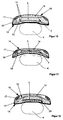
- FIG. 21 shows the arrangement of the reinforcement rings in detail.
- the bellows is replaced by a telescopic arrangement of several rings 34.
- the rings 34 are either sealed against one another or the cushion 19 already described is arranged as a fillable element inside the rings 34.
- FIG. 23 shows the arrangement of the rings 34 in detail.
- an extendable cushion element which is connected to a piston.
- a light material preferably plastic, is used as the material for the piston.
- the piston can be acted upon by the gas and realizes the desired movement. He is locked in the position in which contact is made with the head of the occupant.
- An arrangement for locking the position reached in each case in which the contact to the head 10 is made is, can be analog for all of the above-described design variants or also for actuation the support pads are provided.
Landscapes
- Engineering & Computer Science (AREA)
- Mechanical Engineering (AREA)
- Aviation & Aerospace Engineering (AREA)
- Transportation (AREA)
- Physics & Mathematics (AREA)
- Fluid Mechanics (AREA)
- Seats For Vehicles (AREA)
- Chair Legs, Seat Parts, And Backrests (AREA)
Applications Claiming Priority (2)
| Application Number | Priority Date | Filing Date | Title |
|---|---|---|---|
| DE19757533 | 1997-12-23 | ||
| DE19757533A DE19757533C2 (de) | 1997-12-23 | 1997-12-23 | Sicherheits-Fahrzeugsitz |
Publications (2)
| Publication Number | Publication Date |
|---|---|
| EP0925997A2 true EP0925997A2 (fr) | 1999-06-30 |
| EP0925997A3 EP0925997A3 (fr) | 1999-12-08 |
Family
ID=7853184
Family Applications (1)
| Application Number | Title | Priority Date | Filing Date |
|---|---|---|---|
| EP98250445A Withdrawn EP0925997A3 (fr) | 1997-12-23 | 1998-12-22 | Siège de sécurité pour véhicules |
Country Status (2)
| Country | Link |
|---|---|
| EP (1) | EP0925997A3 (fr) |
| DE (1) | DE19757533C2 (fr) |
Cited By (11)
| Publication number | Priority date | Publication date | Assignee | Title |
|---|---|---|---|---|
| DE19938698A1 (de) * | 1999-08-14 | 2001-02-15 | Volkswagen Ag | Fahrzeugsitz |
| GB2363323A (en) * | 2000-06-15 | 2001-12-19 | Autoliv Dev | Head-rest |
| EP1176049A2 (fr) | 2000-07-26 | 2002-01-30 | DaimlerChrysler AG | Appui-tête |
| GB2339385B (en) * | 1998-07-10 | 2002-02-27 | Autoliv Dev | Improvements in or relating to a vehicle seat |
| DE10025657A1 (de) * | 2000-05-24 | 2002-03-28 | Lear Corp Gmbh & Co Kg | Fahrzeugsitz |
| US6715829B2 (en) | 2000-06-15 | 2004-04-06 | Autoliv Development Ab | Head-rest |
| EP1486384A2 (fr) * | 2003-06-12 | 2004-12-15 | Takata Corporation | Siège d'enfant avec airbag |
| EP1795428A1 (fr) * | 2005-12-12 | 2007-06-13 | Inventus Engineering GmbH | Dispositif d'absorption d'énergie avec un liquide |
| US8408370B2 (en) | 2005-12-12 | 2013-04-02 | Inventus Engineering Gmbh | Energy absorbing element |
| CN103386946A (zh) * | 2013-07-04 | 2013-11-13 | 长春富维—江森自控汽车饰件系统有限公司 | 气压式联动座椅防鞭打系统 |
| CN114084093A (zh) * | 2021-11-12 | 2022-02-25 | 合众新能源汽车有限公司 | 一种汽车座椅的防鞭打机构 |
Families Citing this family (27)
| Publication number | Priority date | Publication date | Assignee | Title |
|---|---|---|---|---|
| DE19800078B4 (de) * | 1998-01-02 | 2008-07-10 | Volkswagen Ag | Fahrzeugsitz mit einer Kopfstütze |
| GB2347078B (en) * | 1999-02-26 | 2002-12-18 | Autoliv Dev | Improvements in or relating to a head-rest |
| SE9900756L (sv) * | 1999-03-03 | 2000-04-03 | Gustaf Bodin | Säkerhetsstol för fordon |
| DE19910666A1 (de) * | 1999-03-11 | 2000-09-14 | Volkswagen Ag | Sitz für einen Insassen eines Kraftfahrzeuges |
| DE29916167U1 (de) | 1999-09-14 | 2001-01-25 | Johnson Controls GmbH, 51399 Burscheid | Aktive Kopfstütze mit Gassackmodul |
| DE19946404C2 (de) * | 1999-09-28 | 2003-10-30 | Siemens Restraint Systems Gmbh | System zur schlagartigen Reduzierung des Abstandes zwischen Kopfstütze und Kopf eines Fahrzeuginsassen |
| DE19961172A1 (de) * | 1999-12-17 | 2001-06-28 | Volkswagen Ag | Fahrzeugsitz |
| FR2802484B1 (fr) * | 1999-12-20 | 2002-02-15 | Faure Bertrand Equipements Sa | Siege de vehicule dote d'un systeme de protection du cou en cas de choc arriere |
| DE10004766B4 (de) * | 2000-02-03 | 2004-10-28 | Keiper Gmbh & Co. Kg | Kopfstütze für einen Fahrzeugsitz |
| DE10006906B4 (de) * | 2000-02-16 | 2004-02-05 | Faurecia Autositze Gmbh & Co. Kg | Rückenlehne eines Fahrzeugsitzes mit einer Kopfstütze |
| DE10028717A1 (de) * | 2000-06-09 | 2002-02-14 | Daimler Chrysler Ag | Rückenlehne mit Kopfstütze eines Kraftfahrzeugsitzes |
| DE10031232A1 (de) * | 2000-06-27 | 2002-01-31 | Wolfgang Stelzenmueller | Sicherheitssitz |
| DE10033913B4 (de) * | 2000-07-05 | 2009-07-09 | Volkswagen Ag | Kopfstütze für einen Fahrzeugsitz, insbesondere für einen Kraftfahrzeugsitz |
| DE10035762A1 (de) | 2000-07-22 | 2002-01-31 | Daimler Chrysler Ag | Abgasturbolader für eine Brennkraftmaschine und Verfahren zum Betrieb eines Abgasturboladers |
| DE20100155U1 (de) | 2001-01-05 | 2001-05-10 | TRW Occupant Restraint Systems GmbH & Co. KG, 73553 Alfdorf | Fahrzeugsitz |
| WO2002068237A1 (fr) | 2001-02-24 | 2002-09-06 | Keiper, Gmbh & Co | Appui-tete pour un siege de vehicule |
| EP1327557B8 (fr) * | 2002-01-14 | 2007-07-04 | Seat, S.A. | Appui-tête pour sièges d'automobile |
| DE10215054B4 (de) | 2002-04-05 | 2007-01-18 | Keiper Gmbh & Co.Kg | Kopfstütze für einen Fahrzeugsitz |
| KR101011079B1 (ko) | 2002-12-21 | 2011-01-25 | 카이퍼 게엠베하 운트 코. 카게 | 충격-작동식 머리받침 |
| DE10325472A1 (de) | 2003-06-05 | 2004-12-30 | Keiper Gmbh & Co. Kg | Crashaktive Kopfstütze |
| DE102004035582B3 (de) | 2004-07-22 | 2006-02-02 | Keiper Gmbh & Co.Kg | Crashaktive Kopfstütze |
| DE102007036466A1 (de) | 2006-12-18 | 2008-06-19 | Brose Fahrzeugteile Gmbh & Co. Kommanditgesellschaft, Coburg | Crash-optimierter Kraftfahrzeugsitz |
| DE102007044824B4 (de) | 2007-09-20 | 2019-07-04 | Autoliv Development Ab | Sicherheitseinrichtung für einen Kraftfahrzeugsitz und Kraftfahrzeugsitz |
| DE102008024871A1 (de) * | 2008-05-23 | 2009-11-26 | GM Global Technology Operations, Inc., Detroit | Kraftfahrzeugsitz mit einem be- und entlüftbaren Kissen und einer Ventilanordnung für das Kissen |
| IT1393551B1 (it) * | 2009-04-07 | 2012-04-27 | Toscana Gomma S P A | Cuscino smorzante per la protezione da colpo di frusta |
| DE102009052397B9 (de) * | 2009-11-10 | 2014-01-23 | Autoliv Development Ab | Fahrzeugsitz mit mehreren integrierten Airbageinrichtungen und Verfahren zur Ansteuerung eines Fahrzeugsitzes mit mehreren integrierten Airbageinrichtungen |
| FR3017081A1 (fr) * | 2014-02-04 | 2015-08-07 | Peugeot Citroen Automobiles Sa | Dispositif d'appui d'une tete et/ou d'un cou, a housse et piece extensibles en cas de choc, pour un dossier de siege |
Citations (4)
| Publication number | Priority date | Publication date | Assignee | Title |
|---|---|---|---|---|
| DE3900495A1 (de) | 1989-01-10 | 1990-07-26 | Bayerische Motoren Werke Ag | Kopfstuetze fuer einen kraftfahrzeugsitz |
| US5378043A (en) | 1993-06-01 | 1995-01-03 | General Motors Corporation | Vehicle pivotal headrest |
| DE29601798U1 (de) | 1996-02-02 | 1996-05-30 | Trw Occupant Restraint Systems Gmbh, 73551 Alfdorf | Fahrzeugsitz mit einem in der Rückenlehne angeordneten Gassack |
| DE29710511U1 (de) | 1997-06-16 | 1997-10-16 | Trw Occupant Restraint Systems Gmbh, 73551 Alfdorf | Fahrzeugsitz mit einer Kopfstütze |
Family Cites Families (5)
| Publication number | Priority date | Publication date | Assignee | Title |
|---|---|---|---|---|
| EP0593845A1 (fr) * | 1992-10-23 | 1994-04-27 | Tandberg Data A/S | Air bag pour appui-tête d'un véhicule activé par des chocs arrière |
| SE9402877L (sv) * | 1994-08-30 | 1996-05-15 | Autosafe Automobile I Stockhol | Anordning för att motverka pisksnärtskador |
| SE9601835D0 (sv) * | 1996-05-14 | 1996-05-14 | Ltg Safecontrol Automotive Ab | Fordonssäte med variabel elasticitet |
| DE29614978U1 (de) * | 1996-08-28 | 1997-01-02 | Trw Occupant Restraint Systems Gmbh, 73551 Alfdorf | Fahrzeugsitz mit einer an der Rückenlehne verstellbaren Kopfstütze |
| DE19739093B4 (de) * | 1996-09-21 | 2006-08-24 | Volkswagen Ag | Höhenverstellbare Kopfstütze für einen Kraftfahrzeugsitz |
-
1997
- 1997-12-23 DE DE19757533A patent/DE19757533C2/de not_active Expired - Lifetime
-
1998
- 1998-12-22 EP EP98250445A patent/EP0925997A3/fr not_active Withdrawn
Patent Citations (4)
| Publication number | Priority date | Publication date | Assignee | Title |
|---|---|---|---|---|
| DE3900495A1 (de) | 1989-01-10 | 1990-07-26 | Bayerische Motoren Werke Ag | Kopfstuetze fuer einen kraftfahrzeugsitz |
| US5378043A (en) | 1993-06-01 | 1995-01-03 | General Motors Corporation | Vehicle pivotal headrest |
| DE29601798U1 (de) | 1996-02-02 | 1996-05-30 | Trw Occupant Restraint Systems Gmbh, 73551 Alfdorf | Fahrzeugsitz mit einem in der Rückenlehne angeordneten Gassack |
| DE29710511U1 (de) | 1997-06-16 | 1997-10-16 | Trw Occupant Restraint Systems Gmbh, 73551 Alfdorf | Fahrzeugsitz mit einer Kopfstütze |
Cited By (18)
| Publication number | Priority date | Publication date | Assignee | Title |
|---|---|---|---|---|
| GB2339385B (en) * | 1998-07-10 | 2002-02-27 | Autoliv Dev | Improvements in or relating to a vehicle seat |
| DE19938698A1 (de) * | 1999-08-14 | 2001-02-15 | Volkswagen Ag | Fahrzeugsitz |
| DE10025657A1 (de) * | 2000-05-24 | 2002-03-28 | Lear Corp Gmbh & Co Kg | Fahrzeugsitz |
| GB2363323B (en) * | 2000-06-15 | 2004-02-18 | Autoliv Dev | Improvements in or relating to a head-rest |
| GB2363323A (en) * | 2000-06-15 | 2001-12-19 | Autoliv Dev | Head-rest |
| US6715829B2 (en) | 2000-06-15 | 2004-04-06 | Autoliv Development Ab | Head-rest |
| US6824211B2 (en) | 2000-07-26 | 2004-11-30 | Daimlerchrysler Ag | Head restraint and method of making and using same |
| EP1176049A3 (fr) * | 2000-07-26 | 2004-01-28 | DaimlerChrysler AG | Appui-tête |
| EP1176049A2 (fr) | 2000-07-26 | 2002-01-30 | DaimlerChrysler AG | Appui-tête |
| EP1486384A2 (fr) * | 2003-06-12 | 2004-12-15 | Takata Corporation | Siège d'enfant avec airbag |
| EP1486384A3 (fr) * | 2003-06-12 | 2005-01-19 | Takata Corporation | Siège d'enfant avec airbag |
| US7293828B2 (en) | 2003-06-12 | 2007-11-13 | Takata Corporation | Child seat with deployable side airbags |
| EP1795428A1 (fr) * | 2005-12-12 | 2007-06-13 | Inventus Engineering GmbH | Dispositif d'absorption d'énergie avec un liquide |
| US7677370B2 (en) | 2005-12-12 | 2010-03-16 | Inventus Engineering Gmbh | Energy absorbing device |
| US8292048B2 (en) | 2005-12-12 | 2012-10-23 | Inventus Engineering Gmbh | Energy absorbing device operating with a free-flowing medium |
| US8408370B2 (en) | 2005-12-12 | 2013-04-02 | Inventus Engineering Gmbh | Energy absorbing element |
| CN103386946A (zh) * | 2013-07-04 | 2013-11-13 | 长春富维—江森自控汽车饰件系统有限公司 | 气压式联动座椅防鞭打系统 |
| CN114084093A (zh) * | 2021-11-12 | 2022-02-25 | 合众新能源汽车有限公司 | 一种汽车座椅的防鞭打机构 |
Also Published As
| Publication number | Publication date |
|---|---|
| DE19757533A1 (de) | 1998-10-01 |
| EP0925997A3 (fr) | 1999-12-08 |
| DE19757533C2 (de) | 2000-02-10 |
Similar Documents
| Publication | Publication Date | Title |
|---|---|---|
| DE19757533C2 (de) | Sicherheits-Fahrzeugsitz | |
| DE102008029617B4 (de) | Fahrzeugsitzanordnung mit einer Energieabsorptionsvorrichtung | |
| EP1077154B1 (fr) | Siège de véhicule | |
| DE69821513T2 (de) | Kissenvorrichtung für sich bewegenden personen | |
| DE102010036315B4 (de) | Airbag-Baugruppe | |
| DE19800078B4 (de) | Fahrzeugsitz mit einer Kopfstütze | |
| DE19927403C2 (de) | Rückenlehne für einen Fahrzeugsitz | |
| DE102009037778A1 (de) | Kopfstütze | |
| EP2144787A1 (fr) | Système d'assise d'un véhicule automobile et procédé de protection d'un passager | |
| DE19952771A1 (de) | Aktiver Sicherheits-Autokindersitz | |
| DE102011076702A1 (de) | Kindersitz für ein Kraftfahrzeug | |
| DE2036355A1 (de) | Luftsack fur die Verwendung im Innen raum von Kraftfahrzeugen, wobei der unter Atmospharendruck oder etwas über Atmos pharendruck stehende Luftsack vor den Fahr zeuginsassen am Armaturenbrett des Kraft fahrzeuges befestigt ist | |
| DE3829368A1 (de) | Sicherheits-airbagsystem | |
| DE202007010364U1 (de) | Insassenschutzeinrichtung für ein Kraftfahrzeug | |
| EP1176049A2 (fr) | Appui-tête | |
| DE2125923A1 (de) | Vorrichtung zum Schutz von Fahrzeuginsassen bei Unfällen | |
| DE102006000887A1 (de) | Sicherheitseinrichtung | |
| DE2447874A1 (de) | Sicherheitseinrichtung | |
| DE19628836A1 (de) | Gassackanordnung mit Ventilationsregelung | |
| DE9017104U1 (de) | Schutzausrüstung | |
| DE102008011246A1 (de) | Fahrzeugsitz, insbesondere Kraftfahrzeugsitz | |
| DE2046426A1 (de) | Sicherheitsvorrichtung für in Landoder Luftfahrzeugen befindliche Personen | |
| DE102021202474A1 (de) | Verstellanordnung zur Verstellung mindestens eines Sitzkonturbereichs eines Fahrzeugsitzes für ein Fahrzeug, Fahrzeugsitz mit der Verstellanordnung und Fahrzeug mit dem Fahrzeugsitz | |
| DE19611588C2 (de) | Kindersicherheitssitz für Kraftfahrzeuge | |
| WO2020074171A1 (fr) | Siège de véhicule |
Legal Events
| Date | Code | Title | Description |
|---|---|---|---|
| PUAI | Public reference made under article 153(3) epc to a published international application that has entered the european phase |
Free format text: ORIGINAL CODE: 0009012 |
|
| AK | Designated contracting states |
Kind code of ref document: A2 Designated state(s): AT BE CH CY DE DK ES FI FR GB GR IE IT LI LU MC NL PT SE |
|
| AX | Request for extension of the european patent |
Free format text: AL;LT;LV;MK;RO;SI |
|
| PUAL | Search report despatched |
Free format text: ORIGINAL CODE: 0009013 |
|
| AK | Designated contracting states |
Kind code of ref document: A3 Designated state(s): AT BE CH CY DE DK ES FI FR GB GR IE IT LI LU MC NL PT SE |
|
| AX | Request for extension of the european patent |
Free format text: AL;LT;LV;MK;RO;SI |
|
| AKX | Designation fees paid | ||
| REG | Reference to a national code |
Ref country code: DE Ref legal event code: 8566 |
|
| STAA | Information on the status of an ep patent application or granted ep patent |
Free format text: STATUS: THE APPLICATION IS DEEMED TO BE WITHDRAWN |
|
| 18D | Application deemed to be withdrawn |
Effective date: 20000609 |