EP0925887B1 - Object separating method, and method of manufacturing semiconductor substrate - Google Patents
Object separating method, and method of manufacturing semiconductor substrate Download PDFInfo
- Publication number
- EP0925887B1 EP0925887B1 EP19980310411 EP98310411A EP0925887B1 EP 0925887 B1 EP0925887 B1 EP 0925887B1 EP 19980310411 EP19980310411 EP 19980310411 EP 98310411 A EP98310411 A EP 98310411A EP 0925887 B1 EP0925887 B1 EP 0925887B1
- Authority
- EP
- European Patent Office
- Prior art keywords
- layer
- substrate
- jet
- bonded substrate
- pressure
- Prior art date
- Legal status (The legal status is an assumption and is not a legal conclusion. Google has not performed a legal analysis and makes no representation as to the accuracy of the status listed.)
- Expired - Lifetime
Links
Images


Classifications
-
- H—ELECTRICITY
- H01—ELECTRIC ELEMENTS
- H01L—SEMICONDUCTOR DEVICES NOT COVERED BY CLASS H10
- H01L21/00—Processes or apparatus adapted for the manufacture or treatment of semiconductor or solid state devices or of parts thereof
-
- H—ELECTRICITY
- H01—ELECTRIC ELEMENTS
- H01L—SEMICONDUCTOR DEVICES NOT COVERED BY CLASS H10
- H01L21/00—Processes or apparatus adapted for the manufacture or treatment of semiconductor or solid state devices or of parts thereof
- H01L21/67—Apparatus specially adapted for handling semiconductor or electric solid state devices during manufacture or treatment thereof; Apparatus specially adapted for handling wafers during manufacture or treatment of semiconductor or electric solid state devices or components ; Apparatus not specifically provided for elsewhere
- H01L21/683—Apparatus specially adapted for handling semiconductor or electric solid state devices during manufacture or treatment thereof; Apparatus specially adapted for handling wafers during manufacture or treatment of semiconductor or electric solid state devices or components ; Apparatus not specifically provided for elsewhere for supporting or gripping
- H01L21/6835—Apparatus specially adapted for handling semiconductor or electric solid state devices during manufacture or treatment thereof; Apparatus specially adapted for handling wafers during manufacture or treatment of semiconductor or electric solid state devices or components ; Apparatus not specifically provided for elsewhere for supporting or gripping using temporarily an auxiliary support
-
- B—PERFORMING OPERATIONS; TRANSPORTING
- B26—HAND CUTTING TOOLS; CUTTING; SEVERING
- B26F—PERFORATING; PUNCHING; CUTTING-OUT; STAMPING-OUT; SEVERING BY MEANS OTHER THAN CUTTING
- B26F3/00—Severing by means other than cutting; Apparatus therefor
- B26F3/004—Severing by means other than cutting; Apparatus therefor by means of a fluid jet
-
- H—ELECTRICITY
- H01—ELECTRIC ELEMENTS
- H01L—SEMICONDUCTOR DEVICES NOT COVERED BY CLASS H10
- H01L21/00—Processes or apparatus adapted for the manufacture or treatment of semiconductor or solid state devices or of parts thereof
- H01L21/67—Apparatus specially adapted for handling semiconductor or electric solid state devices during manufacture or treatment thereof; Apparatus specially adapted for handling wafers during manufacture or treatment of semiconductor or electric solid state devices or components ; Apparatus not specifically provided for elsewhere
- H01L21/67005—Apparatus not specifically provided for elsewhere
- H01L21/67011—Apparatus for manufacture or treatment
- H01L21/67092—Apparatus for mechanical treatment
-
- H—ELECTRICITY
- H01—ELECTRIC ELEMENTS
- H01L—SEMICONDUCTOR DEVICES NOT COVERED BY CLASS H10
- H01L2924/00—Indexing scheme for arrangements or methods for connecting or disconnecting semiconductor or solid-state bodies as covered by H01L24/00
- H01L2924/30—Technical effects
- H01L2924/301—Electrical effects
- H01L2924/30105—Capacitance
-
- Y—GENERAL TAGGING OF NEW TECHNOLOGICAL DEVELOPMENTS; GENERAL TAGGING OF CROSS-SECTIONAL TECHNOLOGIES SPANNING OVER SEVERAL SECTIONS OF THE IPC; TECHNICAL SUBJECTS COVERED BY FORMER USPC CROSS-REFERENCE ART COLLECTIONS [XRACs] AND DIGESTS
- Y10—TECHNICAL SUBJECTS COVERED BY FORMER USPC
- Y10S—TECHNICAL SUBJECTS COVERED BY FORMER USPC CROSS-REFERENCE ART COLLECTIONS [XRACs] AND DIGESTS
- Y10S156/00—Adhesive bonding and miscellaneous chemical manufacture
- Y10S156/934—Apparatus having delaminating means adapted for delaminating a specified article
- Y10S156/941—Means for delaminating semiconductive product
-
- Y—GENERAL TAGGING OF NEW TECHNOLOGICAL DEVELOPMENTS; GENERAL TAGGING OF CROSS-SECTIONAL TECHNOLOGIES SPANNING OVER SEVERAL SECTIONS OF THE IPC; TECHNICAL SUBJECTS COVERED BY FORMER USPC CROSS-REFERENCE ART COLLECTIONS [XRACs] AND DIGESTS
- Y10—TECHNICAL SUBJECTS COVERED BY FORMER USPC
- Y10T—TECHNICAL SUBJECTS COVERED BY FORMER US CLASSIFICATION
- Y10T156/00—Adhesive bonding and miscellaneous chemical manufacture
- Y10T156/11—Methods of delaminating, per se; i.e., separating at bonding face
- Y10T156/1126—Using direct fluid current against work during delaminating
-
- Y—GENERAL TAGGING OF NEW TECHNOLOGICAL DEVELOPMENTS; GENERAL TAGGING OF CROSS-SECTIONAL TECHNOLOGIES SPANNING OVER SEVERAL SECTIONS OF THE IPC; TECHNICAL SUBJECTS COVERED BY FORMER USPC CROSS-REFERENCE ART COLLECTIONS [XRACs] AND DIGESTS
- Y10—TECHNICAL SUBJECTS COVERED BY FORMER USPC
- Y10T—TECHNICAL SUBJECTS COVERED BY FORMER US CLASSIFICATION
- Y10T156/00—Adhesive bonding and miscellaneous chemical manufacture
- Y10T156/12—Surface bonding means and/or assembly means with cutting, punching, piercing, severing or tearing
- Y10T156/1374—Surface bonding means and/or assembly means with cutting, punching, piercing, severing or tearing with means projecting fluid against work
-
- Y—GENERAL TAGGING OF NEW TECHNOLOGICAL DEVELOPMENTS; GENERAL TAGGING OF CROSS-SECTIONAL TECHNOLOGIES SPANNING OVER SEVERAL SECTIONS OF THE IPC; TECHNICAL SUBJECTS COVERED BY FORMER USPC CROSS-REFERENCE ART COLLECTIONS [XRACs] AND DIGESTS
- Y10—TECHNICAL SUBJECTS COVERED BY FORMER USPC
- Y10T—TECHNICAL SUBJECTS COVERED BY FORMER US CLASSIFICATION
- Y10T156/00—Adhesive bonding and miscellaneous chemical manufacture
- Y10T156/19—Delaminating means
-
- Y—GENERAL TAGGING OF NEW TECHNOLOGICAL DEVELOPMENTS; GENERAL TAGGING OF CROSS-SECTIONAL TECHNOLOGIES SPANNING OVER SEVERAL SECTIONS OF THE IPC; TECHNICAL SUBJECTS COVERED BY FORMER USPC CROSS-REFERENCE ART COLLECTIONS [XRACs] AND DIGESTS
- Y10—TECHNICAL SUBJECTS COVERED BY FORMER USPC
- Y10T—TECHNICAL SUBJECTS COVERED BY FORMER US CLASSIFICATION
- Y10T29/00—Metal working
- Y10T29/49—Method of mechanical manufacture
- Y10T29/49815—Disassembling
- Y10T29/49821—Disassembling by altering or destroying work part or connector
-
- Y—GENERAL TAGGING OF NEW TECHNOLOGICAL DEVELOPMENTS; GENERAL TAGGING OF CROSS-SECTIONAL TECHNOLOGIES SPANNING OVER SEVERAL SECTIONS OF THE IPC; TECHNICAL SUBJECTS COVERED BY FORMER USPC CROSS-REFERENCE ART COLLECTIONS [XRACs] AND DIGESTS
- Y10—TECHNICAL SUBJECTS COVERED BY FORMER USPC
- Y10T—TECHNICAL SUBJECTS COVERED BY FORMER US CLASSIFICATION
- Y10T83/00—Cutting
- Y10T83/364—By fluid blast and/or suction
Definitions
- the present invention relates to a method of separating an object and to a method of manufacturing a semiconductor substrate employing such method.
- a substrate (SOI substrate) having an SOI (Silicon On Insulator) structure is known as a substrate having a single-crystal Si layer on an insulating layer.
- SOI substrate Silicon On Insulator
- a device using this SOI substrate has many advantages that cannot be achieved by ordinary Si substrates. Examples of the advantages are as follows.
- an SOS Silicon On Sapphire
- CVD Chemical Vapor Deposition
- This SOS technology was once recognized as the most matured SOI technology.
- the SOS technology has not been put into practical use to date because, e.g., a large amount of crystal defects are produced by lattice mismatch in the interface between the Si layer and the underlying sapphire substrate, aluminum that forms the sapphire substrate mixes in the Si layer, the substrate is expensive, and it is difficult to obtain a large area.
- the present applicant has disclosed a new SOI technology in Japanese Patent Laid-Open No. 5-21338.
- a first substrate obtained by forming a non-porous single-crystal layer on a single-crystal semiconductor substrate having a porous layer is bonded to a second substrate via an insulating layer (SiO 2 ), and the two substrates are separated from the porous layer to transfer the non-porous single-crystal layer to the second substrate.
- This technology is advantageous in that the SOI layer has high film thickness uniformity, the crystal defect density in the SOI layer can be decreased, the SOI layer has high surface planarity, no expensive special fabrication apparatus is necessary, and SOI substrates having SOI films about a few hundred ⁇ to 10 ⁇ m thick can be fabricated by the same fabrication apparatus.
- the present applicant has disclosed another technology in Japanese Patent Laid-Open No.7-302889 in which, after the first and second substrates described above are bonded, the first substrate is separated from the second substrate without breaking, and the separated first substrate is reused by smoothening the surface and again forming a porous layer. Since the first substrate can be economically used, this technology has the advantages that the fabrication cost can be largely reduced and the fabrication process is also simple.
- the present invention has been made in consideration of the above situation, and has as its object to apply a method as defined in claim 1 suitable to separate semiconductor substrates or other objects, and a method of manufacturing a semiconductor substrate.
- a method of separating an object which is performed by ejecting a jet of fluid from a jet unit onto the object to be separated.
- the object to be separated is one that has a fragile layer as a separation layer.
- the fragile layer may be, for example, a porous layer or a microcavitied layer (i.e. a layer having a distribution of microcavities.
- the method of the present invention is further characterised by a control step of changing the pressure of the fluid ejected from the jet unit in accordance with progress of object separation processing, while the object separation processing progresses from a peripheral portion of the object to a central portion of the object.
- Japanese Laid Open Patent Application JP 09 167724A (and also United States Patent US 5783022, a family member thereof) describes a debonding method in which a pressurized liquid jet is directed at the interface between bonded wafers with sufficient pressure to overcome the wafer bonding and separate the two wafers. It is said to be preferable that the jetting pressure should be at least twice the bonding strength between wafers.
- the pressurized fluid is used neither to overcome bonding forces, nor to remove material by milling, but instead to generate and propagate a fault in a fragile layer, thus breaking the fragile layer and effecting separation.
- the object to be separated may be of plate shape, in which case it may be separated by injecting the fluid against the plate shaped object in a planar direction thereof.
- control step preferably comprises reducing the pressure of the fluid ejected from the jet unit from a set pressure as object separation processing progresses from the vicinity of the peripheral portion of the separation layer of the object to be separated.
- control step preferably comprises raising the pressure of the fluid ejected from the jet unit from a set pressure as object separation processing progresses to the vicinity of the central portion of the separation layer of the object to be separated.
- control step preferably comprises setting the pressure of the fluid ejected from the jet unit to be higher as object separation processing progresses in the vicinities of the peripheral and central portions of the separation layer of the object and setting the pressure of the fluid ejected from the jet unit to be lower as object separation processing progresses in an intermediate portion of the separation layer of the object between the vicinities of the peripheral and the central portions thereof.
- control step may comprise changing the pressure of the fluid from the jet unit in accordance with the relative positional relationship between the jet unit and the object.
- control step may comprise changing the pressure of the fluid ejected from the jet unit as a function of time.
- the separating method preferably further comprises performing separation processing for the object while scanning the jet unit along the separation layer of the object to be separated.
- the separating method preferably further comprises performing separation processing for the object while rotating the object about an axis perpendicular to the separation layer of the object.
- a method of manufacturing a semiconductor substrate comprising steps of:
- the step of preparing the substrate may be performed by:
- the step of preparing the substrate may be performed by:
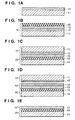
- Figs. 1A to 1E are views for explaining a method of manufacturing an SOI substrate according to the first embodiment of the present invention.
- a single-crystal Si substrate 11 is prepared, and a porous Si layer 12 is formed by anodizing on the surface of the single-crystal Si substrate 11.
- a single-crystal Si layer 13 as a non-porous layer is epitaxially grown on the porous Si layer 12. After this, the surface of the single-crystal Si layer 13 is oxidized to form an SiO 2 layer 15. With this process, a first substrate 10 is formed.
- a single-crystal Si substrate 14 is prepared as a second substrate 20.
- the first and the second substrates 10 and 20 are brought into contact with each other at room temperature such that the SiO 2 layer 15 of the first substrate 10 faces the second substrate 20.
- the first and the second substrates 10 and 20 are bonded by anode bonding, pressing, heating, or a combination thereof. With this process, the second substrate 20 and the SiO 2 layer 15 are firmly bonded.
- the SiO 2 layer 15 may be formed on the single-crystal Si substrate 11 side, as described above, or may be formed on the second substrate 20 or on both the single-crystal Si substrate 11 and the second substrate 20 sides as far as the state shown in Fig. 1C is obtained by bringing the first and second substrates into contact.
- Fig. 1D the two substrates bonded to each other are separated at the porous Si layer 12.
- the second substrate side has a multilayered structure of porous Si layer 12", single-crystal Si layer 13, SiO 2 layer 15, and single-crystal Si substrate 14.
- a porous Si layer 12' is formed on the single-crystal Si substrate 11.
- the remaining porous Si layer 12' is removed from the substrate 10'.
- the surface of the substrate 10' is planarized, as needed, so the substrate 10' is used again as a single-crystal Si substrate 11 for forming a first substrate 10.
- the porous layer 12" on the second substrate side (10" + 20) is selectively removed.
- a substrate having a multilayered structure of single-crystal Si layer 13, insulating layer 15, and single-crystal Si substrate 14, i.e., an SOI structure is obtained.
- a separating apparatus for selectively ejecting a high-pressure liquid or gas (fluid) to the porous Si layer as a separation region is used to separate the substrate stack into two substrates at the separation region.
- This separating apparatus uses a water jet method.
- the water jet method ejects a high-speed, high-pressure stream of water upon an object to, e.g., cut or process a ceramic, a metal, a concrete, a resin, a rubber, or a wood member, remove a coating film from the surface, or clean the surface ("Water Jet", Vol. 1, No. 1, page 4, (1984)).
- This separating apparatus ejects a high-speed, high-pressure stream of fluid to the porous layer (separation region) of the bonded substrate stack as a fragile structure portion in the direction of substrate surface to selectively break the porous layer, thereby separating the substrate at the porous layer.
- the stream will be referred to as a "jet” hereinafter.
- the fluid forming a jet will be referred to as a "jet medium".
- the jet medium it is possible to use an water, organic solvent such as alcohol, an acid such as fluoric acid or nitric acid, an alkali such as potassium hydroxide, a gas such as air, nitrogen gas, carbonic acid gas, rare gas, or an etching gas, or a plasma.
- a jet is ejected to the porous layer (separation region) exposed to the side surface of the bonded substrate stack, thereby removing the porous layer from the peripheral portion to the central portion.
- the bonded substrate stack is separated into two substrates by removing only the separation region with low mechanical strength without damaging the main body. Even when the side surface of the bonded substrate stack is covered with some thin layer, and the porous layer is not exposed, the thin layer can be removed by the jet, so the bonded substrate stack can be separated by the above-described method.
- Figs. 2A and 2B are views showing a force acting on the bonded substrate stack in the presence and absence of a V-shaped groove.
- Fig. 2A shows a bonded substrate stack having a V-shaped groove 22.
- Fig. 2B shows a bonded substrate stack having no V-shaped groove.
- a force (to be referred to as a separation force hereinafter) is applied outward from the center of the bonded substrate stack, as indicated by an arrow 23.
- a force is applied inward from the side surface of the bonded substrate stack, as indicated by an arrow 24.
- the separation force does not act unless the side surface of the porous layer 12 as the separation region is removed by a jet 21.
- the separation force acts on the bonded substrate stack as far as the bonded substrate stack has the V-shaped groove 22, as shown in Fig. 2A, so the thin layer can be easily broken.
- a width W1 of the V-shaped groove 22 is preferably equal to or larger than a diameter d of the jet 21.
- a diameter d of the jet 21 For example, assume that each of the first substrate 10 and the second substrate 20 has a thickness of about 1 mm, and the bonded substrate stack has a thickness of 2 mm. Since the width W1 of the V-shaped groove 22 is normally 1 mm, the diameter of the jet is preferably 1 mm or less. Since a general water jet apparatus uses a jet with a diameter of 0.1 to 0.5 mm, such a general water jet apparatus (e.g., a water jet nozzle) can be used.
- the nozzle for ejecting a jet can have not only a circular shape but any other shapes.
- a slit-like nozzle is employed to eject a jet having a long rectangular section, the jet is efficiently injected into the separation region (inserted between the two substrates).
- the jet ejection conditions are determined in accordance with the type of separation region (e.g., a porous layer) or the shape of the side surface of the bonded substrate stack.
- Important parameters as the jet ejection conditions are the pressure applied to the jet medium, the jet scanning speed, the width or diameter of the nozzle (the nozzle diameter is almost the same as the jet diameter), the nozzle shape, the distance between the nozzle and the separation region, and the flow rate of the jet medium.
- the following techniques are used to separate the bonded substrate stack. 1) The jet is injected into the separation layer in a direction parallel to the bonding interface while the nozzle is scanned along the separation layer. 2) The jet is injected into the separation layer in a direction parallel to the bonding interface while the bonded substrate stack is scanned. 3) The jet is injected into the separation layer in a direction parallel to the bonding interface and simultaneously scanned in a fan shape at a pivot near the nozzle. 4) The jet is injected into the separation layer in a direction parallel to the bonding interface while the bonded substrate stack is rotated about nearly the centre of the bonded substrate stack (this technique is particularly effective when the bonded substrate stack has a disk shape).
- the jet is injected into the separation layer in a direction parallel to the bonding interface while the jet nozzle directing the centre of the bonded substrate stack is scanned along the side surface of the bonded substrate stack.
- the jet need not always be ejected to be perfectly parallel to the bonding interface.
- the separation force applied to the bonded substrate stack in the axial direction is preferably several hundred gf per cm 2 .
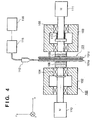
- FIG. 3 is a view showing the schematic arrangement of a separating apparatus according to the preferred embodiment of the present invention.
- a separating apparatus 100 injects a jet into the porous layer of the bonded substrate stack to separate the bonded substrate stack into two substrates.
- the separating apparatus 100 has substrate holding portions 108 and 109 having vacuum chuck mechanisms 108a and 109a.
- a bonded substrate stack 101 is sandwiched by the substrate holding portions 108 and 109 and held.
- the bonded substrate stack 101 has a porous layer 101b as a fragile structure.
- the separating apparatus 100 separates the bonded substrate stack into two substrates 101a and 101c at the porous layer 101b.
- the bonded substrate stack is set such that the substrate 101a is placed on the first substrate 10' side in Fig. 1D and the substrate 101c is placed on the second substrate (10" + 20) side in Fig. 1D.
- the substrate holding portions 108 and 109 are present on the same central axis.
- the substrate holding portion 108 is coupled to one end of a rotary shaft 106 which is rotatably axially supported by a support base 102 through bearings 104.
- the other end of the rotary shaft 106 is coupled to the rotary shaft of a driving source (e.g., a motor) 110 fixed on the support portion 110.
- the rotational force generated by the driving source 110 rotates the bonded substrate stack 101 vacuum-chucked by the substrate holding portion 108.
- the driving source 110 rotates the rotary shaft 106 at a designated rotation speed in accordance with an instruction from a controller (not shown).
- the substrate holding portion 109 is coupled to one end of a rotary shaft 107 which is rotatably and slidably axially supported by a support portion 103 through bearings 105.
- the other end of the rotary shaft 107 is coupled to a driving source (e.g., a motor) 111.
- the speed at which the driving source 110 rotates the rotary shaft 106 and that at which the driving source 111 rotates the rotary shaft 107 must apparently equal each other to prevent the bonded substrate stack 101 from twisting.
- Both the driving sources 110 and 111 need not always be prepared, and either one of them may suffice.
- the driving source 110 when only the driving source 110 is used, before the bonded substrate stack 101 is separated, the rotary shaft 106, substrate holding portion 108, bonded substrate stack 101, substrate holding portion 109, and rotary shaft 107 integrally rotate. After the bonded substrate stack 101 is separated into two substrates, the members on the rotary shaft 107 side come to a halt.
- the rotational force generated by one driving source may be branched into two forces so that the rotary shafts 106 and 107 are rotated by the branched rotational forces, respectively.
- a spring 113 for pressing the bonded substrate stack 101 is attached to the support portion 103 supporting the rotary shaft 107. Therefore, even when the bonded substrate stack 101 is not chucked by the vacuum chuck mechanisms 108a and 109a, the two substrates separated by the jet ejected from a jet nozzle 112 do not drop. In addition, when the bonded substrate stack 101 is separated while being pressed, the bonded substrate stack 101 can be stably held during separation.
- a spring for pressing the bonded substrate stack 101 may also be arranged on the rotary shaft 106 side.
- the separating apparatus 100 has an adjustment mechanism for adjusting the interval between the substrate holding portions 108 and 109.
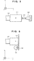
- Fig. 5 is a view showing the first arrangement of the adjustment mechanism.
- Fig. 5 shows an adjustment mechanism using an air cylinder 122.
- the air cylinder 122 is fixed on, e.g., the support portion 103.
- the driving source 111 is moved by a piston rod 121.
- the air cylinder 122 is controlled to move the driving source 111 in a direction in which the interval between the substrate holding portions 108 and 109 increases (in the positive direction of X-axis). In this state, the bonded substrate stack 101 is set between the substrate holding portions 108 and 109, and driving of the piston rod 121 by the air cylinder 122 is canceled.
- the substrate holding portion 109 presses the bonded substrate stack 101 by the action of the spring 113.
- Fig. 6 is a view showing the second arrangement of the adjustment mechanism.
- Fig. 6 shows an adjustment mechanism using an eccentric cam 131 and a motor.
- the eccentric cam 131 is coupled to the motor (not shown).
- the interval between the substrate holding portions 108 and 109 is adjusted by reciprocally moving a driving plate 132 coupled to the rear end of the motor 111.
- the spring 113 applies a force to the rotary shaft 107 in the negative direction of X-axis.
- a gap is formed between the eccentric cam 131 and the driving plate 132. Therefore, when the bonded substrate stack 101 is to be held, a press force acts on the bonded substrate stack 101.
- the above mechanism for adjusting the interval between the substrate holding portions 108 and 109 may also be mounted on the substrate holding portion 108 side.
- a high-pressure pump 115 is coupled to the jet nozzle 112.
- a high-pressure jet medium e.g., water
- a jet is ejected from the jet nozzle 112.
- the pressure applied to the jet medium by the high-pressure pump 115 is controlled by a pressure control section 116.
- the bonded substrate stack 101 is inserted between the substrate holding portions 108 and 109 by a conveyor robot and held while the center of the bonded substrate stack 101 matches that of the substrate holding portions 108 and 109.
- the bonded substrate stack 101 is vacuum-chucked by the substrate holding portion 108.
- the substrate holding portion 109 is pressed against the bonded substrate stack 101 by the force of the spring 113. More specifically, when the adjustment mechanism shown in Fig. 5 is employed to adjust the interval between the substrate holding portions 108 and 109, driving of the piston rod 121 by the air cylinder 122 is canceled. When the adjustment mechanism shown in Fig. 6 is employed, the eccentric cam 131 is rotated such that the press force of the spring 113 acts on the bonded substrate stack 101.
- the bonded substrate stack 101 When separation processing is to be executed, the bonded substrate stack 101 need not always be vacuum-chucked by the vacuum chuck mechanisms 108a and 109a. This is because the bonded substrate stack 101 is held by the press force of the spring 113. However, when a weak press force is used, the bonded substrate stack 101 is preferably vacuum-chucked.
- the rotary shafts 106 and 107 are rotated by the driving sources 110 and 111 in synchronism with each other.
- the high-pressure jet medium e.g., water
- the high-pressure pump 115 is sent from the high-pressure pump 115 to the jet nozzle 112 while the pressure is controlled by the pressure control section 116, thereby ejecting a high-speed, high-pressure jet from the jet nozzle 112.
- the ejected jet is injected into the separation region of the bonded substrate stack 101.
- the porous layer 101b or the fragile structure of the bonded substrate stack 101 is broken, so the bonded substrate stack 101 is separated into two substrates at the porous layer 101b.
- the two separated substrates 101a and 101c are physically split from each other. More specifically, when the adjustment mechanism shown in Fig. 5 is employed to adjust the interval between the substrate holding portions 108 and 109, the piston rod 121 is driven by the air cylinder 122 in the positive direction of X-axis (direction in which the spring 113 compresses) while the substrates are vacuum-chucked by the substrate holding portions 108 and 109, respectively.
- the adjustment mechanism shown in Fig. 5 is employed to adjust the interval between the substrate holding portions 108 and 109
- the piston rod 121 is driven by the air cylinder 122 in the positive direction of X-axis (direction in which the spring 113 compresses) while the substrates are vacuum-chucked by the substrate holding portions 108 and 109, respectively.
- the adjustment mechanism shown in Fig. 5 is employed to adjust the interval between the substrate holding portions 108 and 109, the piston rod 121 is driven by the air cylinder 122 in the positive direction of X-axis (direction in which the spring
- the eccentric cam 131 is rotated to drive the rotary shaft 107 in the positive direction of X-axis (direction in which the spring 113 compresses) while the substrates are vacuum-chucked by the substrate holding portions 108 and 109, respectively.
- the substrates 101a and 101c are completely split, as shown in Fig. 4, jet ejection is stopped, and the substrates are detached from the substrate holding portions 108 and 109 by, e.g., the conveyor robot.
- the jet nozzle 112 may be fixed in position but is preferably movable. This is because the position of the jet nozzle 112 is preferably adjusted in accordance with the type or size of bonded substrate stack 101.
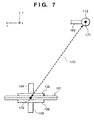
- Fig. 7 is a view showing the driving robot of the jet nozzle 112.
- a driving robot 160 shown in Fig. 7 moves the jet nozzle 112 along a path 170.
- the driving robot 160 moves the jet nozzle 112 to a retreat position 171.
- the driving robot 160 moves the jet nozzle 112 to an operation position 172.
- the jet nozzle 112 when the jet nozzle 112 is retreated in attaching/detaching the bonded substrate stack 101, the operation of attaching/detaching the bonded substrate stack 101 and, more particularly, the operation of attaching/detaching the bonded substrate stack 101 using the conveyor robot can be efficiently performed.
- the bonded substrate stack 101 can be separated well without rotating it.
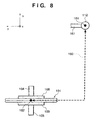
- Fig. 8 is a view showing another example of the driving robot of the jet nozzle 112.
- a driving robot 161 shown in Fig. 8 moves the jet nozzle 112 along a path 180.
- the driving robot 161 moves the jet nozzle 112 to a retreat position 181.
- the driving robot 161 moves the jet nozzle 112 to an operation position 182.
- the jet nozzle 112 when the jet nozzle 112 is retreated in attaching/detaching the bonded substrate stack 101, the operation of attaching/detaching the bonded substrate stack 101 and, more particularly, the operation of attaching/detaching the bonded substrate stack 101 using the conveyor robot can be efficiently performed.
- the bonded substrate stack 101 can be separated well without rotating it.
- the separating apparatus 100 separates the bonded substrate stack while appropriately changing the jet pressure. The reason for this is as follows.
- the jet pressure required to separate the bonded substrate stack 101 changes depending on the portion of the separation region of the bonded substrate stack. For example, the separation force acting on the bonded substrate stack changes between the peripheral and the central portions of the bonded substrate stack 101, so the jet pressure necessary for separation changes between the peripheral and the central portions.
- a high-pressure jet must be used throughout the separation processing. In this case, the bonded substrate stack or separated substrates may break or be damaged, resulting in a low yield.
- the mechanical strength of the separation region can be lowered.
- the separation region readily breaks in the step of bonding or cleaning the two substrates (first and second substrates), so it becomes difficult to manufacture a substrate with desired quality.
- particles may be generated from the broken separation region to contaminate the manufacturing apparatus and the like.
- the pressure is controlled on the basis of the positional relationship between the jet nozzle 112 and the bonded substrate stack 101 or in accordance with time.
- Figs. 9 to 11 are charts showing examples of jet pressure control during separation processing.
- the pressure control section 116 controls the pressure (jet pressure) generated by the high-pressure pump 115, on the basis of one of the control procedures shown in Figs. 9 to 11.
- Fig. 9 shows a control example in which separation processing is executed while fixing the jet nozzle 112 at the operation position 172 or 182 shown in Fig. 7 or 8 and rotating the bonded substrate stack 101.
- the jet pressure is adjusted in three steps.
- a period T1 the peripheral portion of the bonded substrate stack 101 is mainly separated.
- the jet injected into the bonded substrate stack 101 is easily discharged, and the separation force hardly acts on the bonded substrate stack 101, so the jet pressure is set to be high.
- the jet medium is easily discharged, as described above. For this reason, even when the jet pressure is set to be relatively high, the bonded substrate stack 101 does not break.
- the intermediate portion between the peripheral portion and the central portion of the bonded substrate stack 101 (to be simply referred to as an intermediate portion hereinafter) is mainly separated. Since the speed of jet lowers at the intermediate portion, the function of separating the bonded substrate stack 101 weakens due to the impact of the jet medium hitting the porous layer. However, at the intermediate portion, the discharge paths of the jet medium injected into the bonded substrate stack 101 decrease. The separation force due to the pressure of the jet medium injected into the bonded substrate stack 101 increases, and the bonded substrate stack 101 is separated mainly by this separation force. When the same pressure as that for the peripheral portion is applied to the jet medium, the bonded substrate stack 101 may break. For this reason, the pressure of the jet medium is set to be relatively low at the intermediate portion.
- the central portion of the bonded substrate stack 101 is mainly separated.
- the separated portion of the bonded substrate stack 101 warps to increase the discharge paths of the jet medium.
- the pressure of the jet medium is reduced as compared to that in separating the intermediate portion, resulting in a smaller separation force.
- the pressure of the jet medium is preferably set to be higher than that in separating the intermediate portion.
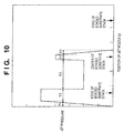
- Fig. 10 shows a control example in which separation processing is executed while scanning the jet nozzle 112 along the separation region of the bonded substrate stack 101 and simultaneously rotating the bonded substrate stack 101.
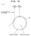
- Fig. 12 is a view showing the force of jet acting on the bonded substrate stack 101.
- the jet is injected toward the peripheral portion of the bonded substrate stack 101, the jet injected against the bonded substrate stack 101 is easily discharged outward, as shown in Fig. 12, and the separation force of jet does not efficiently act on the bonded substrate stack 101.
- the jet is injected toward the central portion of the bonded substrate stack 101, the jet injected against the bonded substrate stack 101 efficiently separates the bonded substrate stack 101.
- the jet pressure is preferably changed in accordance with the positional relationship between the jet nozzle 112 and the bonded substrate stack 101.
- a section Y1 the jet pressure is stabilized.
- the peripheral portion of the bonded substrate stack 101 is mainly separated.
- the jet pressure is preferably set to be relatively high, as described above.
- a section Y3 the intermediate portion of the bonded substrate stack 101 is mainly separated.
- the jet pressure is preferably set to be lower than that in the section Y2 to prevent damage to the bonded substrate stack 101.
- the central portion of the bonded substrate stack 101 is mainly separated.
- the separated portion is close to the central portion by scanning the jet nozzle 112
- the separated portion of the bonded substrate stack 101 warps to increase the discharge paths of the jet medium.
- the pressure of the jet medium is reduced as compared to that in separating the intermediate portion, resulting in a smaller separation force.
- the pressure of the jet medium is preferably set to be higher than that in separating the intermediate portion.
- the bonded substrate stack 101 is separated while rotating it. Hence, separation of the bonded substrate stack 101 is complete when the jet nozzle 112 is scanned from the peripheral portion to the central portion of the bonded substrate stack 101.
- the pressure of the high-pressure pump is gradually reduced to stop the pump operation.
- Fig. 11 shows another control example in which separation processing is executed while scanning the jet nozzle 112 along the separation region of the bonded substrate stack and simultaneously rotating the bonded substrate stack 101.
- the jet pressure is more smoothly changed in the section from the peripheral portion to the intermediate portion and in the section from the intermediate portion to the central portion, as compared to the control example shown in Fig. 10.
- the jet pressure is stabilized.
- the peripheral portion of the bonded substrate stack 101 is mainly separated.
- the jet pressure is preferably set to be relatively high, as described above.
- the intermediate portion of the bonded substrate stack 101 is mainly separated.
- the jet pressure is gradually reduced.
- the jet pressure is gradually raised.
- the central portion of the bonded substrate stack 101 is mainly separated.
- the pressure of the high-pressure pump is gradually reduced to stop the pump operation.
- the bonded substrate stack 101 can be separated by a jet having a more appropriate pressure.
- the methods of changing the pressure of jet ejected from the jet nozzle 112 are not limited to the above three examples.
- the method can be appropriately changed in accordance with the type or size of bonded substrate stack, the type or size of separation layer, or the bonded substrate stack holding method.
- Fig. 13 is a view showing the arrangement of this separating apparatus.
- a separating apparatus 400 has substrate holding portions 404 and 406 having vacuum chucks.
- a bonded substrate stack 101 is sandwiched by the substrate holding portions 404 and 406 and held.
- the bonded substrate stack 101 has a porous layer 101b as a fragile structure.
- the separating apparatus 400 separates the bonded substrate stack into two substrates 101a and 101c at the porous layer 101b.
- the bonded substrate stack is set such that the substrate 101a is placed on the first substrate 10' side in Fig. 1D and the substrate 101c is placed on the second substrate (10" + 20) side in Fig. 1D.
- the substrate holding portion 404 is coupled to one end of a rotary shaft 403 which is rotatably axially supported by a support base 401 through a bearing 405.
- the other end of the rotary shaft 403 is coupled to the rotary shaft of a motor 402.
- the rotational force generated by the motor 402 rotates the bonded substrate stack 101 vacuum-chucked by the substrate holding portion 404.
- the motor 402 rotates the rotary shaft 403 at a designated rotation speed in accordance with an instruction from a controller (not shown).
- the substrate holding portion 406 is coupled to one end of a rotary shaft 408 which is rotatably and slidably axially supported by the support base 401 through a bearings 407.
- a compression spring 409 is attached to the other end of the rotary shaft 408.
- the rotational force of the rotary shaft 403 is transmitted to the substrate holding portion 406 through the bonded substrate stack 101.
- the rotary shaft 403, substrate holding portion 404, bonded substrate stack 101, substrate holding portion 406, rotary shaft 408, and compression spring 409 integrally rotate.
- An air cylinder 411 is arranged on the rear end side (in the X-axis direction) of the rotary shaft 408.
- the air cylinder 411 pushes a piston rod to move the rear end of the rotary shaft 408 in a direction (negative direction of X-axis) in which the compression spring 409 compresses (the state shown in Fig. 13).
- the air cylinder 411 retracts the piston rod 410 (moves the piston rod 410 in the X-axis direction) to allow to separate the bonded substrate stack 101. That is, the air cylinder 411 pushes the piston rod 410 in setting the bonded substrate stack 101 between the substrate holding portions 404 and 406 and retracts the piston rod 410 upon completing setting.
- the bonded substrate stack 101 is mounted on a groove portion 412a of an alignment shaft 412 axially supported by the support base 401 through bearings 413 and 414, and then, the piston rod 410 is pushed to bring the substrate holding portion 406 into contact with the bonded substrate stack 101, as described above. In this state, the vacuum chucks of the substrate holding portions 404 and 406 are actuated.
- Two alignment shafts 412 are preferably arranged along the Y-axis. In this case, only by placing the bonded substrate stack 101 on the two alignment shafts 412, the position of the bonded substrate stack 101 with respect to the three directions, i.e., the X-, Y-, and Z-directions can be defined. This facilitates manual setting of the bonded substrate stack 101. In addition, if a conveyor robot is to be employed, the arrangement of the conveyor robot can be simplified.
- the substrate 101a side moves in the X-axis direction upon completing separation processing to split the two substrates.
- the two substrates are held by, e.g., the conveyor robot, and the suction by the vacuum chucks of the substrate holding portions 404 and 406 is released.
- a high-pressure pump 419 is coupled to the jet nozzle 418.
- a high-pressure jet medium is sent from the high-pressure pump 419 to the jet nozzle 418, a jet is ejected from the jet nozzle 418.
- the pressure applied to the jet medium by the high-pressure pump 419 is controlled by a pressure control section 420 in accordance with one of the control procedures shown in Figs. 9 to 11.
- a shutter 415 is used to prevent the jet from hitting the bonded substrate stack 101 before the jet pressure reaches a predetermined pressure.
- the jet pressure is appropriately controlled while the bonded substrate stack is separated.
- the jet pressure is controlled on the basis of the positional relationship between the jet nozzle 418 and the bonded substrate stack 101 or in accordance with time.
- the control examples shown in Figs. 9 to 11 can also be applied to the separating apparatus 400.
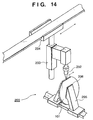
- Fig. 14 is a view showing the arrangement of this separating apparatus.
- substrate holding portions 205 hold a bonded substrate stack 101 fixed in position
- a jet nozzle 202 is scanned by a horizontal driving mechanism 204 along the separation layer of the bonded substrate stack 101.
- Vertical position adjustment of the jet nozzle 202 is performed by a vertical driving mechanism 203.
- the jet pressure is preferably adjusted in accordance with the strength.
- Each of the above separating apparatuses can be applied to separate not only a semiconductor substrate such as a bonded substrate stack but also various objects.
- the object preferably has a fragile structure as a separation layer.
- Each of the above separating apparatuses processes one bonded substrate stack. However, when a plurality of bonded substrate stacks are aligned along the planar direction, and the jet nozzle of the separating apparatus is scanned in the planar direction, the plurality of bonded substrate stacks can be separated at once.
- the plurality of bonded substrate stacks can be sequentially separated.
- the separating apparatuses are especially suitable to separate a substrate having a fragile layer as a separation layer.
- a porous layer, a microcavity layer formed by ion implantation, or a heteroepitaxial layer with distortion or defects concentrated at the crystal lattice can be used.
- the separation layer may be formed from a plurality of layers having different structures, e.g., a plurality of layers having different porosities.
- a first p- or n-type single-crystal Si substrate having a size of 6 inches and a resistivity of 0.01 ⁇ cm was anodized in an HF solution to form a porous Si layer (corresponding to the step shown in Fig. 1A).
- the porous Si is used to form a high-quality epitaxial Si layer on the porous Si layer and also serves as a separation layer.
- the thickness of the porous Si layer is not limited to the above thickness and is preferably several hundred to 0.1 ⁇ m.
- This substrate was oxidized in an oxygen atmosphere at 400°C for 1 hr.
- the inner wall of each pore of the porous Si layer was covered with a thermal oxide film.
- the surface of the porous Si layer was treated with hydrofluoric acid to remove only the oxide film on the surface of the porous Si layer while leaving the oxide film on the inner wall of each pore.
- single-crystal Si was epitaxially grown on the porous Si layer to 0.3 ⁇ m by CVD (Chemical Vapor Deposition).
- the growing conditions were as follows. Source gas SiH 2 Cl 2 /H 2 Gas flow rate 0.5/180 (l/min) Gas pressure 80 (Torr) Temperature 950 (°C) Growth rate 0.3 ( ⁇ m/min)
- an oxide film (SiO 2 layer) having a thickness of 200 nm was formed on the surface of the epitaxial Si layer by thermal oxidation (corresponding to the step shown in Fig. 1B).
- the first substrate and a second Si substrate which was independently prepared were stacked and brought into contact with each other such that the surface of the SiO 2 layer of the first substrate opposed the surface of the second substrate.
- the resultant structure was subjected to a heat treatment at 1,100°C for 1 hr to bond the two substrates (corresponding to the step shown in Fig. 1C).
- the resultant bonded substrate stack 101 was separated using the separating apparatus 200 shown in Fig. 14 (corresponding to the step shown in Fig. 1D). Details will be described below.
- the bonded substrate stack 101 was sandwiched by the substrate holding portions 205 and vertically held. Pure water was ejected from the jet nozzle 202 having a diameter of 0.15 mm at a pressure of 2,200 kgf/cm 2 .
- the jet nozzle 202 was scanned, by the horizontal driving mechanism 204, immediately above the bonded substrate stack 101 along the concave portion of the bevelling at a predetermined speed of 10 mm/sec.
- the jet nozzle 202 moved from a portion immediately above the edge of the bonded substrate stack 101 toward the center (in the scanning direction) of the bonded substrate stack 101 by 15 mm, the jet pressure was maintained at 2,200 kgf/cm 2 .
- the jet pressure was continuously reduced.
- the rate of pressure reduction was -100 kgf/cm 2 per cm of the moving distance of the jet nozzle 202.
- the jet pressure was 1,600 kgf/cm 2 .
- the jet pressure was raised at a rate of 100 kgf/cm 2 per cm of the moving distance of the jet nozzle 202.
- the jet pressure was fixed at 2,200 kgf/cm 2 .
- An elastic member 206 (e.g., Viton, perfluoro rubber, or silicone rubber) is preferably placed at the contact portion between the substrate holding portion 205 and the bonded substrate stack 101.
- the jet can be easily injected against the bonded substrate stack 101 supported by the substrate holding portions 205.
- the bonded substrate stack 101 was separated into two substrates at the porous layer as a separation layer.
- the bonded substrate stack 101 may be held from both sides or held by a substrate holding portion with a vacuum chuck. In the latter case, the bonded substrate stack 101 may be pulled to both sides and held. With this arrangement, the two substrates which are physically separated are immediately split, so damage due to friction between the two substrates can be prevented.
- part of the porous Si layer was transferred to the second substrate side.
- the porous Si layer was left on the surface of the first substrate.
- the porous Si layer transferred to the second substrate was selectively etched under stirring in a mixed solution of 49% hydrofluoric acid and 30% hydrogen peroxide (corresponding to the step shown in Fig. 1E).
- the single-crystal Si layer of the second substrate served as an etch stop layer.
- the porous Si layer was selectively etched and completely removed.
- the etching rate of the non-porous Si single crystal for the above etchant is very low.
- the selectivity ratio to the etching rate of the porous layer is 10 5 or more.
- the etching amount of the non-porous layer (about several ten ⁇ ) is allowable for practical use.
- an SOI substrate having a 0.2- ⁇ m thick single-crystal Si layer on the Si oxide film was formed.
- the thickness of the single-crystal Si layer after the porous Si layer was selectively etched was measured at 100 points on the entire surface. The thickness was 201 nm ⁇ 4 nm.
- the resultant structure was subjected to a heat treatment in hydrogen at 1,100°C for 1 hr, and the surface roughness was evaluated with an atomic force microscope.
- the mean square roughness in a 50- ⁇ m square area was about 0.2 nm. This almost equals that of a commercially available Si wafer.
- the porous Si layer left on the first substrate side was selectively etched under stirring in a mixed solution of water, 40% hydrofluoric acid, and 30% hydrogen peroxide.
- a surface treatment such as hydrogen annealing or surface polishing, the substrate could be recycled as the first or second substrate.
- one bonded substrate stack was processed.
- the jet nozzle of the separating apparatus is scanned in the planar direction, the plurality of bonded substrate stacks can be separated at once.
- the plurality of bonded substrate stacks can be sequentially separated.
- the jet nozzle was scanned.
- the bonded substrate stack may be scanned while the jet nozzle is fixed in position.
- the separating apparatus 200 shown in Fig. 14 was used.
- the separating apparatus 100 shown in Fig. 3 or the separating apparatus 400 shown in Fig. 13 may be used.
- a first p- or n-type single-crystal Si substrate having a resistivity of 0.01 ⁇ cm was subjected to two-step anodizing in an HF solution to form two porous layers (step shown in Fig. 1A).
- the anodizing conditions were as follows.
- a porous Si layer having a two-layered structure was formed.
- the surface porous Si layer anodized at a low current first was used to form a high-quality epitaxial Si layer, and the lower porous Si layer (layer with high porosity) anodized at a high current was used as a separation layer, so the functions of the two layers were separated.
- the thickness of the porous Si layer formed at a low current is not limited to the above thickness (4.5 ⁇ m) and is suitably several hundred to 0.1 ⁇ m.
- the thickness of the porous Si layer formed at a high current is also not limited to the above thickness (2 ⁇ m) as far as a thickness at which the bonded substrate stack can be separated by jet is ensured.
- a third layer or more layers having different porosities may be formed.
- This substrate was oxidized in an oxygen atmosphere at 400°C for 1 hr.
- the inner wall of each pore of the porous Si layer was covered with a thermal oxide film.
- the surface of the porous Si layer was treated with hydrofluoric acid to remove only the oxide film on the surface of the porous Si layer while leaving the oxide film on the inner wall of each pore.
- single-crystal Si was epitaxially grown on the porous Si layer to 0.3 ⁇ m by CVD (Chemical Vapor Deposition).
- the growing conditions were as follows. Source gas SiH 2 Cl 2 /H 2 Gas flow rate 0.5/180 (l/min) Gas pressure 80 (Torr) Temperature 900 (°C) Growth rate 0.3 ( ⁇ m/min)
- an oxide film (SiO 2 layer) having a thickness of 200 nm was formed on the surface of the epitaxial Si layer by thermal oxidation (corresponding to the step shown in Fig. 1B).
- the first substrate and a second Si substrate which was independently prepared were stacked such that the surface of the SiO 2 layer opposed the surface of the second substrate.
- the resultant structure was subjected to a heat treatment at 1,100°C for 1 hr to bond the two substrates (corresponding to the step shown in Fig. 1C).
- the resultant bonded substrate stack 101 was separated using the separating apparatus 400 shown in Fig. 13 (corresponding to the step shown in Fig. 1D). Details will be described below.
- the bonded substrate stack 101 was held vertically between the substrate holding portions 404 and 406, and the piston rod 410 was pushed to bring the substrate holding portion 406 into contact with the bonded substrate stack 101.
- the vacuum chucks of the substrate holding portions 404 and 406 were actuated.
- the distance between the bonded substrate stack 101 and the jet nozzle 418 is preferably 10 to 30 mm. In this example, the distance was set to be 15 mm.
- water as a jet medium was sent from the high-pressure pump 419 to the jet nozzle 418, and stabilization of the jet was waited.
- the jet pressure was set to be 500 kgf/cm 2 under the control of the pressure control section 420.
- the shutter 415 was opened to inject the jet against the concave portion of the bevelling of the bonded substrate stack 101.
- the substrate holding portion 404 was rotated by the motor 402 to rotate the bonded substrate stack 101.
- Separation processing was performed by controlling the high-pressure pump 419 in accordance with the procedure shown in Fig. 9. First, separation processing was started while maintaining the jet pressure at 500 kgf/cm 2 . For a period of 20 to 80 sec after the start of separation processing, separation processing was continued while maintaining the jet pressure at 200 kgf/cm 2 . For a period of 80 to 100 sec after the start of separation processing, the unseparated portion was separated at a higherjet pressure of 400 kgf/cm 2 .
- the bonded substrate stack 101 was separated into two substrates by an appropriate separation force without being damaged.
- the separating apparatus 400 since the two substrates separated from the bonded substrate stack 101 are immediately split from each other, the two substrates after separation are unlikely to bedamaged due to friction.
- the bonded substrate stack can be separated using a low-pressure jet when the bonded substrate stack 101 is separated while being rotated, as in the separating apparatus 400 shown in Fig. 13.
- a jet having a pressure in the neighborhood of 2,000 kgf/cm 2 is required.
- the bonded substrate stack can be separated using a jet having a pressure of several hundred kgf/cm 2 . This is because when the jet is injected against the central portion of the bonded substrate stack 101, the separation force efficiently acts on the internal portion of the bonded substrate stack 101.
- a twisting force may act on the bonded substrate stack 101. If this force poses a problem, another motor is preferably coupled to the substrate holding portion 406 side to drive the substrate holding portions 404 and 406 in synchronism with each other.
- the porous Si layer transferred to the second substrate was selectively etched under stirring in a mixed solution of 49% hydrofluoric acid and 30% hydrogen peroxide (corresponding to the step shown in Fig. 1E).
- the single-crystal Si layer served as an etch stop layer.
- the porous Si layer was selectively etched and completely removed.
- the etching rate of the non-porous Si single crystal for the above etchant is very low.
- the selectivity ratio to the etching rate of the porous layer is 10 5 or more.
- the etching amount of the non-porous layer (about several ten ⁇ ) is allowable for practical use.
- an SOI substrate having a 0.2- ⁇ m thick single-crystal Si layer on the Si oxide film was formed.
- the thickness of the single-crystal Si layer after the porous Si layer was selectively etched was measured at 100 points on the entire surface. The thickness was 201 nm ⁇ 4 nm.
- the resultant structure was subjected to a heat treatment in hydrogen at 1,100°C for 1 hr, and the surface roughness was evaluated with an atomic force microscope.
- the mean square roughness in a 50- ⁇ m square area was about 0.2 nm. This almost equals that of a commercially available Si wafer.
- the porous Si layer left on the first substrate side was selectively etched under stirring in a mixed solution of water, 40% hydrofluoric acid, and 30% hydrogen peroxide.
- a surface treatment such as hydrogen annealing or surface polishing, the substrate could be recycled as the first or second substrate.
- An oxide film (SiO 2 layer) having a thickness of 400 nm was formed on the surface of a first single-crystal Si substrate by thermal oxidation as an insulating layer.
- ions were implanted from the surface of the first substrate such that the projection range stayed in the Si substrate.
- a layer serving as a separation layer was formed as a distortion layer due to a microcavity layer or a heavily doped ion species layer at a depth corresponding to the projection range.
- the first substrate and a second Si substrate which was independently prepared were brought into contact such that the surface of the SiO 2 layer opposed the surface of the second substrate.
- the resultant structure was subjected to a heat treatment at 600°C for 10 hrs to bond the two substrates. Before the two substrates were bonded, the substrates were treated by N 2 plasma or the like to increase the bonding strength.
- the resultant bonded substrate stack 101 was separated using the separating apparatus 400 shown in Fig. 13. Separation processing was executed under the same conditions as those in Example 2 except that the jet pressure was raised by about 150 kgf/cm 2 throughout processing.
- part of the separation layer was transferred to the second substrate side.
- the separation layer was left on the surface of the first substrate.
- the separation surface of the separated second substrate was polished by about 300 nm by a CMP (Chemical Mechanical Polishing) apparatus to remove the damage layer formed upon ion implantation and separation processing and was planarized.
- CMP Chemical Mechanical Polishing
- an SOI substrate having a 0.2- ⁇ m thick single-crystal Si layer on the Si oxide film was formed.
- the thickness of the single-crystal Si layer was measured at 100 points on the entire surface. The thickness was 201 nm ⁇ 4 nm.
- the resultant structure was subjected to a heat treatment in hydrogen at 1,100°C for 1 hr, and the surface roughness was evaluated with an atomic force microscope.
- the mean square roughness in a 50- ⁇ m square area was about 0.3 nm. This almost equals that of a commercially available Si wafer.
- the surface region of the single-crystal Si substrate (first substrate) is transferred to the second substrate via the separation layer formed by ion implantation.
- an epitaxial wafer may be used. A separation layer is formed at the lower portion of the epitaxial layer by ion implantation, and the epitaxial layer is transferred to the second substrate by separating the substrate at the separation layer.
- the SiO 2 layer on the surface of the first substrate maybe removed.
- the first substrate is bonded to the second substrate, and the substrate is separated at the separation layer, thereby transferring the epitaxial layer and SiO 2 layer to the second substrate.
- An SOI substrate was manufactured by the same method as in Example 2 except that separation processing was executed while scanning the jet nozzle on the separation region of the bonded substrate stack.
- a substrate 101 formed by the same method as in Example 2 was separated using the separating apparatus shown in Fig. 3. Details will be described below.
- the bonded substrate stack 101 was vertically held between the substrate holding portions 108 and 109 while being pressed by the substrate holding portion 109.
- the distance between the bonded substrate stack 101 and the jet nozzle 112 is preferably 10 to 30 mm. In this example, the distance was set to be 15 mm.
- the jet pressure was controlled on the basis of the control example shown in Fig. 10.
- the jet nozzle 112 was retreated to a position where the jet ejected from the jet nozzle 112 did not hit the bonded substrate stack 101 (the jet nozzle 112 may be retreated in advance) .
- a jet medium was sent from the high-pressure pump 115 to the jet nozzle 112 to eject a jet from the jet nozzle 112, and at the same time, scanning of the jet nozzle 112 was started (section Y1). In the section Y1, the jet pressure was raised to 500 kgf/cm 2 .
- the peripheral portion of the bonded substrate stack 101 was mainly separated while maintaining the jet pressure at 500 kgf/cm 2 .
- the separation force can be efficiently applied to the bonded substrate stack 101.
- the section Y3 was set for 10 to 90 mm from the edge portion of the bonded substrate stack 101, i.e., the portion where separation was started (to be referred to as a separation start position).
- the jet pressure was set to be 200 kgf/cm 2 .
- the section Y4 was set for 90 to 100 mm from the separation start position of the bonded substrate stack 101.
- the jet pressure was raised to 400 kgf/cm 2 to separate the unseparated portion.
- an appropriate separation force can be applied to the internal portion of the bonded substrate stack 101. For this reason, the bonded substrate stack 101 can be efficiently separated while preventing damage to it.
- This example is the same as in Example 4 except that the jet pressure was controlled on the basis of the control example shown in Fig. 11.
- the bonded substrate stack 101 formed by the same method as in Example 2 was vertically supported between the substrate holding portions 108 and 109 while being pressed by the substrate holding portion 109.
- the distance between the bonded substrate stack 101 and the jet nozzle 112 is preferably 10 to 30 mm. In this example, the distance was set to be 15 mm.
- the jet pressure was controlled on the basis of the control example shown in Fig. 11.
- the jet nozzle 112 was retreated to a position where the jet ejected from the jet nozzle 112 did not hit the bonded substrate stack 101 (the jet nozzle 112 may be retreated in advance) .
- a jet medium was sent from the high-pressure pump 115 to the jet nozzle 112 to eject a jet from the jet nozzle 112, and at the same time, scanning of the jet nozzle 112 was started (section Y1). In the section Y1, the jet pressure was raised to 500 kgf/cm 2 .
- the peripheral portion of the bonded substrate stack 101 was mainly separated while maintaining the jet pressure at 500 kgf/cm 2 .
- the separation force can be efficiently applied to the bonded substrate stack 101.
- the section Y3 was set for 10 to 60 mm from the separation start position of the bonded substrate stack 101.
- separation processing was executed while reducing the jet pressure from 500 kgf/cm 2 to 200 kgf/cm 2 .
- damage to the stack can be prevented.
- the section Y4 was set for 60 to 90 mm from the separation start position, and separation processing was executed while gradually raising the jet pressure to 400 kgf/cm 2 .
- the reason why the jet pressure is gradually raised in the section Y4 is as follows. As the separation region comes close to the central portion of the bonded substrate stack 101, the discharge paths of the jet medium injected into the bonded substrate stack 101 increase, and accordingly, the separation force acting on the internal portion of the bonded substrate stack 101 weakens. To efficiently perform separation processing, the separation force must be compensated.
- the section Y5 was set for 90 to 100 mm from the separation start position of the bonded substrate stack 101.
- the unseparated portion was separated while raising the jet pressure to 400 kgf/cm 2 .
- the jet pressure is raised in separating the central portion of the bonded substrate stack 101, an appropriate separation force can be applied to the internal portion of the bonded substrate stack 101, so the bonded substrate stack 101 can be efficiently separated while preventing damage to it.
Landscapes
- Engineering & Computer Science (AREA)
- Computer Hardware Design (AREA)
- Power Engineering (AREA)
- Microelectronics & Electronic Packaging (AREA)
- Physics & Mathematics (AREA)
- Condensed Matter Physics & Semiconductors (AREA)
- General Physics & Mathematics (AREA)
- Manufacturing & Machinery (AREA)
- Life Sciences & Earth Sciences (AREA)
- Forests & Forestry (AREA)
- Mechanical Engineering (AREA)
- Mechanical Treatment Of Semiconductor (AREA)
- Container, Conveyance, Adherence, Positioning, Of Wafer (AREA)
- Weting (AREA)
- Electrical Discharge Machining, Electrochemical Machining, And Combined Machining (AREA)
- Inorganic Insulating Materials (AREA)
- Materials For Photolithography (AREA)
- Perforating, Stamping-Out Or Severing By Means Other Than Cutting (AREA)
Applications Claiming Priority (2)
| Application Number | Priority Date | Filing Date | Title |
|---|---|---|---|
| JP36101497 | 1997-12-26 | ||
| JP36101497A JP4323577B2 (ja) | 1997-12-26 | 1997-12-26 | 分離方法および半導体基板の製造方法 |
Publications (2)
| Publication Number | Publication Date |
|---|---|
| EP0925887A1 EP0925887A1 (en) | 1999-06-30 |
| EP0925887B1 true EP0925887B1 (en) | 2003-08-06 |
Family
ID=18471832
Family Applications (1)
| Application Number | Title | Priority Date | Filing Date |
|---|---|---|---|
| EP19980310411 Expired - Lifetime EP0925887B1 (en) | 1997-12-26 | 1998-12-18 | Object separating method, and method of manufacturing semiconductor substrate |
Country Status (9)
| Country | Link |
|---|---|
| US (1) | US6436226B1 (enExample) |
| EP (1) | EP0925887B1 (enExample) |
| JP (1) | JP4323577B2 (enExample) |
| KR (1) | KR19990063514A (enExample) |
| CN (1) | CN1153264C (enExample) |
| AT (1) | ATE246577T1 (enExample) |
| AU (1) | AU736845B2 (enExample) |
| DE (1) | DE69816955T2 (enExample) |
| SG (1) | SG76581A1 (enExample) |
Families Citing this family (22)
| Publication number | Priority date | Publication date | Assignee | Title |
|---|---|---|---|---|
| US6382292B1 (en) * | 1997-03-27 | 2002-05-07 | Canon Kabushiki Kaisha | Method and apparatus for separating composite member using fluid |
| TW508690B (en) | 1999-12-08 | 2002-11-01 | Canon Kk | Composite member separating method, thin film manufacturing method, and composite member separating apparatus |
| JP2002075915A (ja) * | 2000-08-25 | 2002-03-15 | Canon Inc | 試料の分離装置及び分離方法 |
| JP2002075917A (ja) * | 2000-08-25 | 2002-03-15 | Canon Inc | 試料の分離装置及び分離方法 |
| KR100383265B1 (ko) * | 2001-01-17 | 2003-05-09 | 삼성전자주식회사 | 웨이퍼 보호 테이프 제거용 반도체 제조장치 |
| FR2823373B1 (fr) * | 2001-04-10 | 2005-02-04 | Soitec Silicon On Insulator | Dispositif de coupe de couche d'un substrat, et procede associe |
| JP2002340989A (ja) * | 2001-05-15 | 2002-11-27 | Semiconductor Energy Lab Co Ltd | 測定方法、検査方法及び検査装置 |
| JP2002353423A (ja) * | 2001-05-25 | 2002-12-06 | Canon Inc | 板部材の分離装置及び処理方法 |
| JP2003017667A (ja) * | 2001-06-29 | 2003-01-17 | Canon Inc | 部材の分離方法及び分離装置 |
| JP2003017668A (ja) * | 2001-06-29 | 2003-01-17 | Canon Inc | 部材の分離方法及び分離装置 |
| US7187162B2 (en) * | 2002-12-16 | 2007-03-06 | S.O.I.Tec Silicon On Insulator Technologies S.A. | Tools and methods for disuniting semiconductor wafers |
| US20050150597A1 (en) * | 2004-01-09 | 2005-07-14 | Silicon Genesis Corporation | Apparatus and method for controlled cleaving |
| DE102010010334B4 (de) * | 2010-03-04 | 2012-01-19 | Satisloh Ag | Vorrichtung zum Abblocken von optischen Werkstücken, insbesondere Brillengläsern |
| US9765289B2 (en) * | 2012-04-18 | 2017-09-19 | Taiwan Semiconductor Manufacturing Company, Ltd. | Cleaning methods and compositions |
| JP6145415B2 (ja) * | 2014-02-27 | 2017-06-14 | 東京エレクトロン株式会社 | 剥離方法、プログラム、コンピュータ記憶媒体、剥離装置及び剥離システム |
| KR102305505B1 (ko) * | 2014-09-29 | 2021-09-24 | 삼성전자주식회사 | 웨이퍼 서포팅 시스템 디본딩 이니시에이터 및 웨이퍼 서포팅 시스템 디본딩 방법 |
| DE102014118017A1 (de) * | 2014-12-05 | 2016-06-09 | Ev Group E. Thallner Gmbh | Substratstapelhalterung, Container und Verfahren zur Trennung eines Substratstapels |
| CN105931997B (zh) * | 2015-02-27 | 2019-02-05 | 胡迪群 | 暂时性复合式载板 |
| CN109148333A (zh) * | 2018-08-03 | 2019-01-04 | 武汉新芯集成电路制造有限公司 | 一种晶圆分离装置及方法 |
| KR102204732B1 (ko) * | 2019-11-11 | 2021-01-19 | (주)더숨 | Soi 기판 제조 방법 |
| WO2024039868A1 (en) * | 2022-08-19 | 2024-02-22 | Lumileds Llc | Open-ended holder device for removing sapphire substrate |
| WO2024204570A1 (ja) * | 2023-03-31 | 2024-10-03 | 芝浦メカトロニクス株式会社 | 基板分離装置、基板処理装置および基板分離方法 |
Family Cites Families (13)
| Publication number | Priority date | Publication date | Assignee | Title |
|---|---|---|---|---|
| US4507898A (en) * | 1981-04-13 | 1985-04-02 | International Harvester Company | Abrasive liquid jet cutting apparatus |
| US4702042A (en) * | 1984-09-27 | 1987-10-27 | Libbey-Owens-Ford Co. | Cutting strengthened glass |
| US4703591A (en) * | 1985-04-15 | 1987-11-03 | Libbey-Owens-Ford Co. | Ultra-high pressure abrasive jet cutting of glass |
| US4962879A (en) | 1988-12-19 | 1990-10-16 | Duke University | Method for bubble-free bonding of silicon wafers |
| KR950014609B1 (ko) | 1990-08-03 | 1995-12-11 | 캐논 가부시끼가이샤 | 반도체부재 및 반도체부재의 제조방법 |
| FR2681472B1 (fr) | 1991-09-18 | 1993-10-29 | Commissariat Energie Atomique | Procede de fabrication de films minces de materiau semiconducteur. |
| US5212451A (en) | 1992-03-09 | 1993-05-18 | Xerox Corporation | Single balanced beam electrostatic voltmeter modulator |
| FR2699852B1 (fr) * | 1992-12-29 | 1995-03-17 | Gaz De France | Procédé et dispositif d'usinage à jet de fluide haute pression asservi. |
| US5339715A (en) * | 1993-09-02 | 1994-08-23 | Davidson Textron Inc. | Programmable pressure control system |
| JP3257580B2 (ja) | 1994-03-10 | 2002-02-18 | キヤノン株式会社 | 半導体基板の作製方法 |
| FR2725074B1 (fr) | 1994-09-22 | 1996-12-20 | Commissariat Energie Atomique | Procede de fabrication d'une structure comportant une couche mince semi-conductrice sur un substrat |
| KR0165467B1 (ko) * | 1995-10-31 | 1999-02-01 | 김광호 | 웨이퍼 디본더 및 이를 이용한 웨이퍼 디본딩법 |
| US6048411A (en) * | 1997-05-12 | 2000-04-11 | Silicon Genesis Corporation | Silicon-on-silicon hybrid wafer assembly |
-
1997
- 1997-12-26 JP JP36101497A patent/JP4323577B2/ja not_active Expired - Fee Related
-
1998
- 1998-12-15 SG SG1998005834A patent/SG76581A1/en unknown
- 1998-12-15 US US09/211,876 patent/US6436226B1/en not_active Expired - Lifetime
- 1998-12-18 DE DE1998616955 patent/DE69816955T2/de not_active Expired - Lifetime
- 1998-12-18 EP EP19980310411 patent/EP0925887B1/en not_active Expired - Lifetime
- 1998-12-18 AT AT98310411T patent/ATE246577T1/de not_active IP Right Cessation
- 1998-12-24 AU AU98187/98A patent/AU736845B2/en not_active Ceased
- 1998-12-25 CN CNB981263356A patent/CN1153264C/zh not_active Expired - Fee Related
- 1998-12-26 KR KR1019980058986A patent/KR19990063514A/ko not_active Ceased
Also Published As
| Publication number | Publication date |
|---|---|
| EP0925887A1 (en) | 1999-06-30 |
| AU736845B2 (en) | 2001-08-02 |
| CN1221973A (zh) | 1999-07-07 |
| ATE246577T1 (de) | 2003-08-15 |
| KR19990063514A (ko) | 1999-07-26 |
| JPH11195569A (ja) | 1999-07-21 |
| JP4323577B2 (ja) | 2009-09-02 |
| DE69816955D1 (de) | 2003-09-11 |
| DE69816955T2 (de) | 2004-06-17 |
| CN1153264C (zh) | 2004-06-09 |
| AU9818798A (en) | 1999-07-15 |
| US6436226B1 (en) | 2002-08-20 |
| SG76581A1 (en) | 2000-11-21 |
Similar Documents
| Publication | Publication Date | Title |
|---|---|---|
| EP0925887B1 (en) | Object separating method, and method of manufacturing semiconductor substrate | |
| US6900114B2 (en) | Separating apparatus, separating method, and method of manufacturing semiconductor substrate | |
| US6521078B2 (en) | Sample separating apparatus and method, and substrate manufacturing method | |
| US6746559B2 (en) | Method and apparatus for separating composite member using fluid | |
| US6427747B1 (en) | Apparatus and method of separating sample and substrate fabrication method | |
| US6653205B2 (en) | Composite member separating method, thin film manufacturing method, and composite member separating apparatus | |
| US6540861B2 (en) | Member separating apparatus and processing apparatus | |
| JPH11274018A (ja) | 複合部材の分離方法および半導体基体の作製方法 | |
| JPH11195570A (ja) | 物体の分離装置及びその方法並びに半導体基体の製造方法 |
Legal Events
| Date | Code | Title | Description |
|---|---|---|---|
| PUAI | Public reference made under article 153(3) epc to a published international application that has entered the european phase |
Free format text: ORIGINAL CODE: 0009012 |
|
| AK | Designated contracting states |
Kind code of ref document: A1 Designated state(s): AT BE DE ES FR GB IT NL SE |
|
| AX | Request for extension of the european patent |
Free format text: AL;LT;LV;MK;RO;SI |
|
| 17P | Request for examination filed |
Effective date: 19991115 |
|
| AKX | Designation fees paid |
Free format text: AT BE DE ES FR GB IT NL SE |
|
| 17Q | First examination report despatched |
Effective date: 20020220 |
|
| GRAH | Despatch of communication of intention to grant a patent |
Free format text: ORIGINAL CODE: EPIDOS IGRA |
|
| GRAH | Despatch of communication of intention to grant a patent |
Free format text: ORIGINAL CODE: EPIDOS IGRA |
|
| GRAA | (expected) grant |
Free format text: ORIGINAL CODE: 0009210 |
|
| AK | Designated contracting states |
Designated state(s): AT BE DE ES FR GB IT NL SE |
|
| PG25 | Lapsed in a contracting state [announced via postgrant information from national office to epo] |
Ref country code: NL Free format text: LAPSE BECAUSE OF FAILURE TO SUBMIT A TRANSLATION OF THE DESCRIPTION OR TO PAY THE FEE WITHIN THE PRESCRIBED TIME-LIMIT Effective date: 20030806 Ref country code: ES Free format text: LAPSE BECAUSE OF FAILURE TO SUBMIT A TRANSLATION OF THE DESCRIPTION OR TO PAY THE FEE WITHIN THE PRESCRIBED TIME-LIMIT Effective date: 20030806 Ref country code: BE Free format text: LAPSE BECAUSE OF FAILURE TO SUBMIT A TRANSLATION OF THE DESCRIPTION OR TO PAY THE FEE WITHIN THE PRESCRIBED TIME-LIMIT Effective date: 20030806 Ref country code: AT Free format text: LAPSE BECAUSE OF FAILURE TO SUBMIT A TRANSLATION OF THE DESCRIPTION OR TO PAY THE FEE WITHIN THE PRESCRIBED TIME-LIMIT Effective date: 20030806 |
|
| REG | Reference to a national code |
Ref country code: GB Ref legal event code: FG4D |
|
| RTI1 | Title (correction) |
Free format text: OBJECT SEPARATING METHOD, AND METHOD OF MANUFACTURING SEMICONDUCTOR SUBSTRATE |
|
| REF | Corresponds to: |
Ref document number: 69816955 Country of ref document: DE Date of ref document: 20030911 Kind code of ref document: P |
|
| PG25 | Lapsed in a contracting state [announced via postgrant information from national office to epo] |
Ref country code: SE Free format text: LAPSE BECAUSE OF FAILURE TO SUBMIT A TRANSLATION OF THE DESCRIPTION OR TO PAY THE FEE WITHIN THE PRESCRIBED TIME-LIMIT Effective date: 20031106 |
|
| NLV1 | Nl: lapsed or annulled due to failure to fulfill the requirements of art. 29p and 29m of the patents act | ||
| ET | Fr: translation filed | ||
| PLBE | No opposition filed within time limit |
Free format text: ORIGINAL CODE: 0009261 |
|
| STAA | Information on the status of an ep patent application or granted ep patent |
Free format text: STATUS: NO OPPOSITION FILED WITHIN TIME LIMIT |
|
| 26N | No opposition filed |
Effective date: 20040507 |
|
| PGFP | Annual fee paid to national office [announced via postgrant information from national office to epo] |
Ref country code: FR Payment date: 20110107 Year of fee payment: 13 |
|
| PGFP | Annual fee paid to national office [announced via postgrant information from national office to epo] |
Ref country code: IT Payment date: 20101217 Year of fee payment: 13 Ref country code: GB Payment date: 20101223 Year of fee payment: 13 |
|
| PGFP | Annual fee paid to national office [announced via postgrant information from national office to epo] |
Ref country code: DE Payment date: 20101231 Year of fee payment: 13 |
|
| GBPC | Gb: european patent ceased through non-payment of renewal fee |
Effective date: 20111218 |
|
| REG | Reference to a national code |
Ref country code: FR Ref legal event code: ST Effective date: 20120831 |
|
| REG | Reference to a national code |
Ref country code: DE Ref legal event code: R119 Ref document number: 69816955 Country of ref document: DE Effective date: 20120703 |
|
| PG25 | Lapsed in a contracting state [announced via postgrant information from national office to epo] |
Ref country code: GB Free format text: LAPSE BECAUSE OF NON-PAYMENT OF DUE FEES Effective date: 20111218 Ref country code: DE Free format text: LAPSE BECAUSE OF NON-PAYMENT OF DUE FEES Effective date: 20120703 |
|
| PG25 | Lapsed in a contracting state [announced via postgrant information from national office to epo] |
Ref country code: IT Free format text: LAPSE BECAUSE OF NON-PAYMENT OF DUE FEES Effective date: 20111218 |
|
| PG25 | Lapsed in a contracting state [announced via postgrant information from national office to epo] |
Ref country code: FR Free format text: LAPSE BECAUSE OF NON-PAYMENT OF DUE FEES Effective date: 20120102 |