EP0924133B1 - Vorrichtung zum kontinuierlichen und luftdichten Umhüllen von Ballen - Google Patents
Vorrichtung zum kontinuierlichen und luftdichten Umhüllen von Ballen Download PDFInfo
- Publication number
- EP0924133B1 EP0924133B1 EP98122820A EP98122820A EP0924133B1 EP 0924133 B1 EP0924133 B1 EP 0924133B1 EP 98122820 A EP98122820 A EP 98122820A EP 98122820 A EP98122820 A EP 98122820A EP 0924133 B1 EP0924133 B1 EP 0924133B1
- Authority
- EP
- European Patent Office
- Prior art keywords
- film
- sensing element
- winding arm
- sensor
- detection
- Prior art date
- Legal status (The legal status is an assumption and is not a legal conclusion. Google has not performed a legal analysis and makes no representation as to the accuracy of the status listed.)
- Expired - Lifetime
Links
- 238000000034 method Methods 0.000 claims abstract description 18
- 230000033001 locomotion Effects 0.000 claims abstract description 7
- 238000001514 detection method Methods 0.000 claims description 25
- 238000004804 winding Methods 0.000 claims description 17
- 239000010902 straw Substances 0.000 claims description 4
- 230000005540 biological transmission Effects 0.000 claims description 3
- 238000010276 construction Methods 0.000 claims description 3
- 238000006243 chemical reaction Methods 0.000 claims 6
- 239000004459 forage Substances 0.000 claims 1
- 230000008054 signal transmission Effects 0.000 claims 1
- 230000003068 static effect Effects 0.000 abstract 1
- 239000000523 sample Substances 0.000 description 5
- 230000006835 compression Effects 0.000 description 3
- 238000007906 compression Methods 0.000 description 3
- 239000011888 foil Substances 0.000 description 3
- 238000013461 design Methods 0.000 description 2
- 238000011161 development Methods 0.000 description 2
- 230000001960 triggered effect Effects 0.000 description 2
- 239000002699 waste material Substances 0.000 description 2
- 239000000853 adhesive Substances 0.000 description 1
- 230000002411 adverse Effects 0.000 description 1
- 239000003795 chemical substances by application Substances 0.000 description 1
- 238000005520 cutting process Methods 0.000 description 1
- 230000006735 deficit Effects 0.000 description 1
- 238000000151 deposition Methods 0.000 description 1
- 238000009826 distribution Methods 0.000 description 1
- 239000000428 dust Substances 0.000 description 1
- 230000003203 everyday effect Effects 0.000 description 1
- 238000004519 manufacturing process Methods 0.000 description 1
- 238000012986 modification Methods 0.000 description 1
- 230000004048 modification Effects 0.000 description 1
- 238000005096 rolling process Methods 0.000 description 1
- 229920006300 shrink film Polymers 0.000 description 1
- 230000011664 signaling Effects 0.000 description 1
- 239000004460 silage Substances 0.000 description 1
- 238000003860 storage Methods 0.000 description 1
- 238000012549 training Methods 0.000 description 1
Images



Classifications
-
- A—HUMAN NECESSITIES
- A01—AGRICULTURE; FORESTRY; ANIMAL HUSBANDRY; HUNTING; TRAPPING; FISHING
- A01F—PROCESSING OF HARVESTED PRODUCE; HAY OR STRAW PRESSES; DEVICES FOR STORING AGRICULTURAL OR HORTICULTURAL PRODUCE
- A01F15/00—Baling presses for straw, hay or the like
- A01F15/07—Rotobalers, i.e. machines for forming cylindrical bales by winding and pressing
- A01F15/071—Wrapping devices
-
- B—PERFORMING OPERATIONS; TRANSPORTING
- B65—CONVEYING; PACKING; STORING; HANDLING THIN OR FILAMENTARY MATERIAL
- B65B—MACHINES, APPARATUS OR DEVICES FOR, OR METHODS OF, PACKAGING ARTICLES OR MATERIALS; UNPACKING
- B65B11/00—Wrapping, e.g. partially or wholly enclosing, articles or quantities of material, in strips, sheets or blanks, of flexible material
- B65B11/04—Wrapping, e.g. partially or wholly enclosing, articles or quantities of material, in strips, sheets or blanks, of flexible material the articles being rotated
-
- B—PERFORMING OPERATIONS; TRANSPORTING
- B65—CONVEYING; PACKING; STORING; HANDLING THIN OR FILAMENTARY MATERIAL
- B65B—MACHINES, APPARATUS OR DEVICES FOR, OR METHODS OF, PACKAGING ARTICLES OR MATERIALS; UNPACKING
- B65B57/00—Automatic control, checking, warning, or safety devices
- B65B57/02—Automatic control, checking, warning, or safety devices responsive to absence, presence, abnormal feed, or misplacement of binding or wrapping material, containers, or packages
- B65B57/04—Automatic control, checking, warning, or safety devices responsive to absence, presence, abnormal feed, or misplacement of binding or wrapping material, containers, or packages and operating to control, or to stop, the feed of such material, containers, or packages
-
- A—HUMAN NECESSITIES
- A01—AGRICULTURE; FORESTRY; ANIMAL HUSBANDRY; HUNTING; TRAPPING; FISHING
- A01F—PROCESSING OF HARVESTED PRODUCE; HAY OR STRAW PRESSES; DEVICES FOR STORING AGRICULTURAL OR HORTICULTURAL PRODUCE
- A01F15/00—Baling presses for straw, hay or the like
- A01F15/07—Rotobalers, i.e. machines for forming cylindrical bales by winding and pressing
- A01F15/071—Wrapping devices
- A01F2015/0725—Film dispensers for film rollers in a satellite type wrapper, e.g. holding and tensioning means for the film roller
-
- A—HUMAN NECESSITIES
- A01—AGRICULTURE; FORESTRY; ANIMAL HUSBANDRY; HUNTING; TRAPPING; FISHING
- A01F—PROCESSING OF HARVESTED PRODUCE; HAY OR STRAW PRESSES; DEVICES FOR STORING AGRICULTURAL OR HORTICULTURAL PRODUCE
- A01F15/00—Baling presses for straw, hay or the like
- A01F15/07—Rotobalers, i.e. machines for forming cylindrical bales by winding and pressing
- A01F15/071—Wrapping devices
- A01F2015/073—Features related to the horizontal rotating arm of a wrapping device of the satellite type
-
- A—HUMAN NECESSITIES
- A01—AGRICULTURE; FORESTRY; ANIMAL HUSBANDRY; HUNTING; TRAPPING; FISHING
- A01F—PROCESSING OF HARVESTED PRODUCE; HAY OR STRAW PRESSES; DEVICES FOR STORING AGRICULTURAL OR HORTICULTURAL PRODUCE
- A01F15/00—Baling presses for straw, hay or the like
- A01F15/07—Rotobalers, i.e. machines for forming cylindrical bales by winding and pressing
- A01F15/071—Wrapping devices
- A01F2015/076—Wrapping device incorporating sensors
Definitions
- the invention relates to a device for continuous and airtight wrapping of crop bales made of hay, straw or withered green waste with a stretchy and self-adhesive Foil according to the preamble of claim 1.
- a wrapping process requires the crop bale in a rotary motion about its horizontal axis of rotation to move.
- the supply roll has to be wrapped of the crop bale with film in a rotary movement by one vertical axis around the crop bale.
- the device is known from DE 44 04 225 A1.
- EP 0 688 287 B1 describes a hydraulic wrapping device discloses a slide over a pair Stretching rollers, which serve to stretch the film around a bale is wrapped out of silage.
- a lack of the above Wrapping device is that no means for Control of the wrapping process are provided. That means, that, for example, a tear of the film or the end of a supply roll only visually through the Driver or operator can be determined. This fact is clear Adversely noticeable especially in combination devices which the wrapping device immediately behind a round baler is arranged and thus by the driver or operator is no longer visible. A tear off the slide or the end of one The supply roll is therefore only determined when a not fully covered crop bales already on the field is filed.
- the light sensors are stationary outside the wrapping device provided.
- Such a device can be used in devices for wrapping crop bales do not provide, because in the rough everyday operation of such Device during field work one with a reflection mirror working signaling device due to the accruing Dust and dirt impairments after a short time Use can no longer work reliably.
- the object of the invention is therefore a device for continuous and airtight wrapping of agricultural crop bales to create, with the help of an easy to manufacture, inexpensive and robust device detection a film tear or the end of the one provided on the supply roll Reliable film during the wrapping process is made possible.
- the device stands out for the continuous and airtight wrapping of crop bales from hay, straw or withered greenery of the above-mentioned Kind by those specified in the characterizing part of claim 1 Characteristics.
- the invention is referred to claims 2 to 12.
- a device for continuous and airtight wrapping of crop bales made of hay, straw, withered Green waste or the like.
- Agricultural stalk or leaf crops is in the path of a film strip between one Storage roll and a crop bale to be wrapped a film stretching device provided, which is arranged downstream of a deflecting element is that by deflecting the film strip during the wrapping process transferred from a rest position to a prestressed position can be. This provides a signal from the information about the operating status during the wrapping process can be derived.
- the signal provided by the deflecting element a reliable one for the rough agricultural Use of suitable recording and forming equipment to perform in which this signal in an operating state descriptive and processable information can be implemented.
- one Wrapping device with one around the body led supply role assumed that a non-contact Detection and reshaping of the deflection element provided signal in an operating state descriptive during the wrapping process and processable information from a rotating Wrapping arm on a stationary frame assembly is achievable.
- An advantageous embodiment of the Invention assumes that the detection and forming device Detection means, which at the stationary Frame assembly are attached, as well as a Resiliently flexible probe element assigned to the wrap arm includes.
- the sensing element and the detection means assigned to each other so that during a Rotation of the wrapping arm around the crop bale at least once an acquisition and reshaping of the of the Deflection signal provided are performed can. It is preferably provided as an angle-like shaped tab formed probe element in one opposite a support tube of the winding arm Position that spatially an area of a extension of the attachment end of the Carrier tube at the transmission output of the frame assembly includes. In the event of a film tear, for example Wrapping arm at the earliest after half a turn and at the latest after one and a half turn in one defined starting position are stopped.
- a simple implementation of the invention includes construction elements, preferably a wire rope with which the provided as a distance from the deflecting element Signal in a purely mechanical way of recording and Forming device can be fed.
- a prone to failure electrical unit, such as a Power source in a battery, generator version or the like. for setting up a circuit on the wrap arm is not needed.
- the contact-free detection is preferably carried out and reshaping that provided by the deflecting element Signals in that in the case of an error-free Sequence of the wrapping process in one large distance when the winding arm rotates the detection agent (s) passes through the crop bales and therefore no switching process on the detection means triggers.
- the detection device (s) at a short distance a switching process on the detection means is triggered.
- the probe element in an advantageous development of the invention it is also conceivable to design the probe element as a circular, resilient in their distance from the detection means attached counter to train that on your Perimeter, for example, with an even distribution Elongated holes is provided. This results in, that the wrap arm, for example in the event of a film tear always the next time the defined one is run Starting position can be stopped.
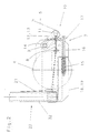
- FIG. 1 in a direction F in the direction of travel Viewing direction shown device for wrapping a crop bale 1 with film is an embodiment with a fixed Changing table 2 for receiving a bale of crop 1 in a rotary motion with a direction of rotation D1 a vertical axis 3 during the wrapping process a supply roll 4 is guided around, a film strip 5 withdrawn from the supply roll 4 and around about a horizontal axis of rotation 6 with a Direction of rotation D2 rotating crop bale 1 wrapped becomes.
- the directions of rotation D1 and D2 in Fig.1 are free chosen and can also be directed in opposite directions his.
- a film stretching device 7 attached, which at least two vertically arranged Includes stretching rollers 8.9.
- the film stretcher 7 is one with the supply roll 4 Unit summarized, the film stretching device 7 and the supply roll 4 in Fig.1 in a defined starting position for the wrapping process are located. That means that in such a Position of the film stretching device 7 and the supply roll 4 neither picking up or depositing a crop bale 1 on or from the changing table 2, another Applying the film strip 5 to a not shown Holding and cutting device is hindered.
- the Film stretching device 7 a deflection element 10 subordinate, that by the deflection of the film strip 5 resilient from a rest position can be transferred into a prestressed position.
- the Deflection element 10 around a deflection roller 11, which at its Ends in holding tabs 12, 13 and over this pivotable about a rotation axis 14 of the stretching roller 9 is stored. It is preferably of a width the deflection roller 11 is based on the width of the film strip 5 corresponds. However, it is conceivable also to perform the guide roller 11 in a smaller width.
- a compression spring 15 is provided, which via a pull rod 16 to one on the upper retaining tab 12 attached bracket 17 acts.
- the rest position the deflection roller 11 is reached when the bracket 17 on holding plates 18, 19 of the film stretching device 7 is present.
- Detection and forming device 20 serve construction elements such as a wire rope 21, the Length adapted to different film widths can be.
- the detection and forming device 20 essentially from one arranged on a rotating winding arm 22 probe 23 and a detection means 24 which is attached to a stationary frame assembly 25.
- a feeler element 23 is shaped as an angle element Tab 26 provided in its lower area an L-shaped section 27 and in its upper region has a U-shaped section 28 and by means of a screw connection 29 and a compression spring 30, which also has a restoring force on the deflecting element 10 exercises, on a retaining tab 31 of the winding arm 22nd is resiliently attached.
- the tactile element 23 and the one or more detection means 24 each other assigned so that during one revolution of the winding arm 22 around the crop bale 1 at least once detection and reshaping of the deflection element 10 provided signal can be performed. It is preferably provided that the angle-like shaped tab 26 formed sensing element 23 in one a support tube 32 of the winding arm 22 opposite Position that spatially an area of a extension of the attachment end of the Support tube 32 at the transmission output of the frame assembly 25 includes.
- a film tear for example the wrap arm 22 with the film stretching device 7 and the supply roll 4 at the earliest after half a turn and at the latest after one and a half turn stopped in the defined starting position (Fig. 1) become.
- A for example, can be used as the detection means 24 electronic sensor 33 are used, in which a Switching process is triggered when, as shown in Fig. 4, mechanically via the wire rope 21 and with the help of the spring force of the compression spring 30 a leg of the U-shaped section 28 with respect to its vertical Distance is brought closer to the sensor 33.
- This makes contact-free recording and reshaping of the signal provided by the deflecting element 10 enables.
- the probe element 23 as a circular, at a distance from the means of detection 24 resiliently attached counter to train with, for example Provide evenly spaced elongated holes is. It follows that the wrap arm 22 with the Film stretching device 7 and the supply roll 4, for example in the event of a film tear, always at next run of the defined starting position stopped can be.
Landscapes
- Engineering & Computer Science (AREA)
- Mechanical Engineering (AREA)
- Life Sciences & Earth Sciences (AREA)
- Environmental Sciences (AREA)
- Storage Of Harvested Produce (AREA)
- Auxiliary Devices For And Details Of Packaging Control (AREA)
- Basic Packing Technique (AREA)
Description
In der Zeichnung stellt im einzelnen dar:
- Fig. 1
- eine perspektivische teilweise schematische Darstellung einer erfindungsgemäßen Vorrichtung zum kontinuierlichen und luftdichten Umhüllen von Körpern in einer in Fahrtrichtung weisenden Betrachtungsrichtung;
- Fig. 2
- eine vergrößerte Darstellung einer Folienstreckvorrichtung in einer Betrachtungsrichtung gemäß Pfeil A in Fig.1;
- Fig. 3
- eine vergrößerte Darstellung einer Erfassungs- und Umformeinrichtung in einer Betrachtungsrichtungsrichtung gemäß Pfeil B in Fig. 1 während des Umhüllungsvorganges;
- Fig. 4
- eine Darstellung ähnlich Fig. 3 zum Zeitpunkt der Erkennung beispielsweise eines Folienabrisses;
Claims (12)
- Vorrichtung zum kontinuierlichen und luftdichten Umhüllen von Erntegutballen (1) aus Heu, Stroh oder angewelktem Grüngut mit einer dehnbaren und selbstanhaftenden Folie, wobei der Umhüllungsvorgang ein Abrollen eines Folienstreifens (5) von einer mittels eines um eine vertikale achse (3) rotierend angetriebenen Wickelarmes (22) um den Erntegutballen (1) in einer Drehbewegung um eine vertikale Achse geführten Vorratsrolle (4) sowie ein schraubenlinienförmiges Umhüllen der vollständigen Oberfläche des Erntegutballens (1) einschließt, mit einer zumindest zwei Streckwalzen (8,9) umfassenden und zwischen der Vorratsrolle (4) und dem Erntegutballen (1) angebrachten Folienstreckvorrichtung (7), dadurch gekennzeichnet, daß der Folienstreckvorrichtung (7) ein Umlenkelement (10) nachgeordnet ist, welches durch die Umlenkung des Folienstreifens (5) beim Umhüllungsvorgang aus einer Ruhelage in eine vorgespannte Lage überführbar ist, und daß das Umlenkelement (10) bei einer Überführung aus seiner Ruhelage in eine vorgespannte Lage und aus einer vorgespannten Lage in seine Ruhelage über rein mechanisch wirkende Konstruktionselemente (21, 23, 26) ein am Wickelarm (22) angeordnetes Tastelement (23) einer Erfassungs- und Umformeinrichtung (20) zur Umformung bzw. Übertragung eines Signals in seiner Lage verändert und eine berührungsfreie Umformung bzw. Übertragung eines Signals von dem Tastelement (23) auf einen an einer ortsfesten Rahmenbaugruppe (25) vorgesehenen Sensor (24,33) der Erfassungs- und Umformeinrichtung (20) erfolgt, wobei das Tastelement (23) und der Sensor (24, 23) innerhalb der Kreisbewegungsbahn des Wickelarmes (22) angeordnet und diese einander derart zugeordnet sind, daß während einer Umdrehung des Wickelarmes (22) um den Erntegutballen (1) zumindest einmal eine Erfassung und Umformung des von dem Umlenkelement (10) bereitgestellten Signals durchführbar ist, und wobei dem Sensor (24, 33) zumindest ein weiteres Erkennungsmittel (34) zum Abfragen des Erreichens einer definierten Ausgangsstellung des Wickelarmes zugeordnet ist.
- Vorrichtung nach Anspruch 1, dadurch gekennzeichnet, daß der Sensor (24, 33) bei sich in der Ausgangsstellung (Fig. 1) befindlichen Baueinheit aus Folienstreckvorrichtung (7) und Vorratsrolle (4) an der ortsfesten Rahmenbaugruppe (25) in einem Bereich zwischen der vertikalen Achse (3) der Antriebsverbindung des Wickelarmes (22) und der Baueinheit aus Folienstreckvorrichtung (7) und Vorratsrolle (4) befindet.
- Vorrichtung nach Anspruch 1 oder 2, dadurch gekennzeichnet, daß der Sensor (24, 33) und das Tastelement (23) zur vertikalen Achse (3) gegenüberliegend und in der Höhe versetzt angeordnet sind.
- Vorrichtung nach einem der Ansprüche 1 bis 3, dadurch gekennzeichnet, daß das Umlenkelement (10) in der Ruhelage entgegen der Federkraft einer Druckfeder (15 ; 30) nachgiebig abgestützt ist.
- Vorrichtung nach einem der Ansprüche 1 bis 4, dadurch gekennzeichnet, daß das Umlenkelement (10) als eine Umlenkrolle ausgebildet ist, welche um eine vertikale Rotationsachse (14) einer der Streckwalzen (8,9) der Folienstreckvorrichtung (7) schwenkbar gelagert ist.
- Vorrichtung nach einem der Ansprüche 1 bis 5, dadurch gekennzeichnet, daß die Erfassungs- und Umformeinrichtung (20) ein Tastelement (23) aufweist, das federnd nachgiebig am Wickelarm (22) gehaltert ist.
- Vorrichtung nach einem der Ansprüche 1 bis 6, dadurch gekennzeichnet, daß das Tastelement (23) als eine winkelähnlich geformte Lasche (26) ausgeführt ist.
- Vorrichtung nach Anspruch 7, dadurch gekennzeichnet, daß das als Lasche (26) geformte Tastelement (23) im unteren Bereichen einen L-förmigen Abschnitt (27) und im oberen Bereich einen U-förmigen Abschnitt (28) aufweist.
- Vorrichtung nach Anspruch 7 oder 8, dadurch gekennzeichnet, daß das Tastelement mittels einer Schraubverbindung (29) und einer Druckfeder (30) an einer Haltelasche (31) des Wickelarmes (22) federnd nachgiebig befestigt ist.
- Vorrichtung nach einem der Ansprüche 1 bis 9, dadurch gekennzeichnet, daß bei einem einarmig ausgebildeten, mit seinem Tragrohr (32) am Getriebeausgang der Rahmenbaugruppe (25) befestigten und angetriebenen Wickelarm (22) das Tastelement (23) im Bereich einer gedanklichen Verlängerung des Befestigungsendes des Tragrohres (32) gehaltert ist.
- Vorrichtung nach einem der Ansprüche 1 bis 6, dadurch gekennzeichnet, daß das Tastelement (23) als eine kreisrunde Zählscheibe ausgebildet ist, die in ihrem Abstand zu dem Sensor (24, 33) federnd nachgiebig am Wickelarm (22) angeordnet ist.
- Vorrichtung nach einem der Ansprüche 1 bis 11, dadurch gekennzeichnet, daß während einer Umdrehung des Wickelarmes (22) um den Erntegutballen (1) eine Erfassung und Umformung des von dem Umlenkelement (10) bereitgestellten Signals zwei oder mehrmals erfolgt.
Applications Claiming Priority (2)
| Application Number | Priority Date | Filing Date | Title |
|---|---|---|---|
| DE19755605A DE19755605C1 (de) | 1997-12-15 | 1997-12-15 | Vorrichtung zum kontinuierlichen und luftdichten Umhüllen von Körpern |
| DE19755605 | 1997-12-15 |
Publications (2)
| Publication Number | Publication Date |
|---|---|
| EP0924133A1 EP0924133A1 (de) | 1999-06-23 |
| EP0924133B1 true EP0924133B1 (de) | 2001-10-31 |
Family
ID=7851910
Family Applications (1)
| Application Number | Title | Priority Date | Filing Date |
|---|---|---|---|
| EP98122820A Expired - Lifetime EP0924133B1 (de) | 1997-12-15 | 1998-12-01 | Vorrichtung zum kontinuierlichen und luftdichten Umhüllen von Ballen |
Country Status (4)
| Country | Link |
|---|---|
| EP (1) | EP0924133B1 (de) |
| AT (1) | ATE207836T1 (de) |
| DE (2) | DE19755605C1 (de) |
| DK (1) | DK0924133T3 (de) |
Families Citing this family (12)
| Publication number | Priority date | Publication date | Assignee | Title |
|---|---|---|---|---|
| EP1090543A1 (de) * | 1999-10-05 | 2001-04-11 | Lely Research Holding AG | Vorrichtung und Verfahren zum Umhüllen von Körpern, insbesondere von Erntegutballen |
| DE20015540U1 (de) | 2000-09-07 | 2001-04-12 | Schuster, Thomas, 87754 Kammlach | Folienwickelvorrichtung |
| EP1222851B1 (de) | 2001-01-12 | 2006-05-10 | Lely Enterprises AG | Ballenwickelgerät |
| EP1310155B1 (de) * | 2001-11-09 | 2007-12-19 | Welger Maschinenfabrik GmbH | Vorrichtung und Verfahren zum Umhüllen von Körpern, insbesondere von Erntegutballen |
| EP1310152A1 (de) * | 2001-11-09 | 2003-05-14 | Lely Enterprises AG | Vorrichtung und verfahren zum Umhüllen von Körpern insbesondere von Erntegutballen |
| EP1310154B1 (de) | 2001-11-09 | 2007-12-19 | Welger Maschinenfabrik GmbH | Vorrichtung zum Umhüllen von Körpern, insbesondere von Erntegutballen |
| EP1310153A1 (de) | 2001-11-09 | 2003-05-14 | Lely Enterprises AG | Vorrichtung zum Umhüllen von Körpern, insbesondere von Erntegutballen |
| DE10322545B4 (de) * | 2003-05-20 | 2012-08-30 | Deere & Company | Vorrichtung zum Überwachen des Laufs von bahnförmigem Material |
| DE10334740A1 (de) * | 2003-07-30 | 2005-03-10 | Deere & Co | Vorrichtung zum Überwachen des Laufs von bahnförmigem Material |
| FI126244B (sv) * | 2014-04-16 | 2016-08-31 | Oy El-Ho Ab | Lantbruksmaskin |
| KR102317665B1 (ko) * | 2015-07-28 | 2021-10-27 | 크버네랜드 그룹 라베나 에스.알.엘. | 베일 포장 기기와, 수확 산물로부터 만들어진 베일을 포장하는 방법 |
| ES2611962B1 (es) * | 2017-03-20 | 2018-02-14 | Condearena, S.L. | Rodillo para máquinas envolvedoras de pacas de forraje y máquina que incorpora dicho rodillo |
Family Cites Families (4)
| Publication number | Priority date | Publication date | Assignee | Title |
|---|---|---|---|---|
| DE9006375U1 (de) * | 1990-06-06 | 1990-09-06 | Develog, Reiner Hannen & Cie, Courtelary | Vorrichtung zum Umwickeln eines Gutstapels mit einer gedehnten Folie |
| WO1994017653A1 (en) * | 1993-02-15 | 1994-08-18 | Kverneland Underhaug A/S | Bale wrapper apparatus |
| GB2275905A (en) * | 1993-03-12 | 1994-09-14 | Kenneth Stephen Eddin Orpen | Hydraulic bale wrapper |
| DE4413838C2 (de) * | 1993-05-06 | 1996-09-26 | Nuetro Maschinen & Anlagen | Verfahren und Vorrichtung zum Umwickeln von Verpackungsgut |
-
1997
- 1997-12-15 DE DE19755605A patent/DE19755605C1/de not_active Expired - Fee Related
-
1998
- 1998-12-01 AT AT98122820T patent/ATE207836T1/de not_active IP Right Cessation
- 1998-12-01 DE DE59801940T patent/DE59801940D1/de not_active Expired - Fee Related
- 1998-12-01 EP EP98122820A patent/EP0924133B1/de not_active Expired - Lifetime
- 1998-12-01 DK DK98122820T patent/DK0924133T3/da active
Also Published As
| Publication number | Publication date |
|---|---|
| EP0924133A1 (de) | 1999-06-23 |
| ATE207836T1 (de) | 2001-11-15 |
| DE19755605C1 (de) | 1999-08-26 |
| DE59801940D1 (de) | 2001-12-06 |
| DK0924133T3 (da) | 2002-01-28 |
Similar Documents
| Publication | Publication Date | Title |
|---|---|---|
| DE2930590C2 (de) | Umhüllvorrichtung | |
| DE60224154T2 (de) | Vorrichtung zum Umhüllen von Körpern, insbesondere von Erntegutballen | |
| DE3424567C2 (de) | ||
| DE4227820A1 (de) | Vorrichtung zur entdeckung von eindringlingen | |
| DE8915767U1 (de) | Automatische Rundballen-Umwickelvorrichtung | |
| EP3984896A1 (de) | Maschine zum schonenden banderolieren empfindlicher güter | |
| DE69601233T2 (de) | Hilfseinrichtung zum Einstellen der Falzabmessungen in einer Falz-Kuvertiermaschine | |
| EP0765809A1 (de) | Verfahren und Vorrichtung zum Verpacken einer Materialbahnrolle | |
| DE19755605C1 (de) | Vorrichtung zum kontinuierlichen und luftdichten Umhüllen von Körpern | |
| EP0958734B1 (de) | Rundballenpresse für landwirtschaftliches Erntegut. | |
| DE1499046A1 (de) | Vorrichtung zum Auf- und Abrollen von Bedeckungselementen wie Planen,Vorhaenge,Geflechte oder Strohmatten | |
| EP0499913B1 (de) | Bindevorrichtung | |
| DE102005001406B4 (de) | Hüllmittelanzeigevorrichtung | |
| DE102010005721B3 (de) | Verfahren und Vorrichtung zum Abschalten oder Abbremsen von Drahtverarbeitungsmaschinen bei Drahtendenerkennung | |
| EP1502493B1 (de) | Vorrichtung zum Umhüllen oder Verpacken von insbesondere landwirtschaftlichen Erntegutballen | |
| EP3081072B1 (de) | Vorrichtung zum umwickeln von erntegutballen | |
| EP0618160A2 (de) | Papierrolle, Papierrollenauspackstation und Verfahren zum Auspacken einer Papierrolle | |
| EP1541008B1 (de) | Umwickeln mit nur einem Folienende | |
| EP0849180B1 (de) | Vorrichtung zum Verpacken einer Materialbahnrolle | |
| EP0668228A2 (de) | Einrichtung zum Herstellen einer Bahnverbindung | |
| EP0815719B1 (de) | Rundballenpresse | |
| DE8321610U1 (de) | Großballenpresse für landwirtschaftliches Erntegut | |
| DE4012741C1 (en) | Crop baling and wrapping machine - incorporates measuring and release unit with adjuster responding to size of bale | |
| DE102005001405B4 (de) | Hüllvorrichtung, insbesondere einer Rundballenpresse | |
| DE1499046C (de) | Verfahrbare Vorrichtung zum Auf- und Abrollen von Bedeckungselementen wie Planen, Vorhänge, Geflechte oder Strohmatten |
Legal Events
| Date | Code | Title | Description |
|---|---|---|---|
| PUAI | Public reference made under article 153(3) epc to a published international application that has entered the european phase |
Free format text: ORIGINAL CODE: 0009012 |
|
| AK | Designated contracting states |
Kind code of ref document: A1 Designated state(s): AT BE CH DE DK ES FI FR GB IE IT LI NL SE |
|
| AX | Request for extension of the european patent |
Free format text: AL;LT;LV;MK;RO;SI |
|
| 17P | Request for examination filed |
Effective date: 19991216 |
|
| AKX | Designation fees paid |
Free format text: AT BE CH DE DK ES FI FR GB IE IT LI NL SE |
|
| RAP1 | Party data changed (applicant data changed or rights of an application transferred) |
Owner name: MASCHINENFABRIK BERNARD KRONE GMBH |
|
| 17Q | First examination report despatched |
Effective date: 20000322 |
|
| GRAG | Despatch of communication of intention to grant |
Free format text: ORIGINAL CODE: EPIDOS AGRA |
|
| GRAG | Despatch of communication of intention to grant |
Free format text: ORIGINAL CODE: EPIDOS AGRA |
|
| GRAH | Despatch of communication of intention to grant a patent |
Free format text: ORIGINAL CODE: EPIDOS IGRA |
|
| GRAH | Despatch of communication of intention to grant a patent |
Free format text: ORIGINAL CODE: EPIDOS IGRA |
|
| GRAA | (expected) grant |
Free format text: ORIGINAL CODE: 0009210 |
|
| AK | Designated contracting states |
Kind code of ref document: B1 Designated state(s): AT BE CH DE DK ES FI FR GB IE IT LI NL SE |
|
| PG25 | Lapsed in a contracting state [announced via postgrant information from national office to epo] |
Ref country code: GB Free format text: LAPSE BECAUSE OF FAILURE TO SUBMIT A TRANSLATION OF THE DESCRIPTION OR TO PAY THE FEE WITHIN THE PRESCRIBED TIME-LIMIT Effective date: 20011031 |
|
| REF | Corresponds to: |
Ref document number: 207836 Country of ref document: AT Date of ref document: 20011115 Kind code of ref document: T |
|
| REG | Reference to a national code |
Ref country code: CH Ref legal event code: EP |
|
| REF | Corresponds to: |
Ref document number: 59801940 Country of ref document: DE Date of ref document: 20011206 |
|
| REG | Reference to a national code |
Ref country code: IE Ref legal event code: FG4D Free format text: GERMAN |
|
| REG | Reference to a national code |
Ref country code: CH Ref legal event code: NV Representative=s name: PATENTANWAELTE FELDMANN & PARTNER AG |
|
| REG | Reference to a national code |
Ref country code: DK Ref legal event code: T3 |
|
| PG25 | Lapsed in a contracting state [announced via postgrant information from national office to epo] |
Ref country code: SE Free format text: LAPSE BECAUSE OF FAILURE TO SUBMIT A TRANSLATION OF THE DESCRIPTION OR TO PAY THE FEE WITHIN THE PRESCRIBED TIME-LIMIT Effective date: 20020131 |
|
| ET | Fr: translation filed | ||
| PG25 | Lapsed in a contracting state [announced via postgrant information from national office to epo] |
Ref country code: ES Free format text: LAPSE BECAUSE OF FAILURE TO SUBMIT A TRANSLATION OF THE DESCRIPTION OR TO PAY THE FEE WITHIN THE PRESCRIBED TIME-LIMIT Effective date: 20020430 |
|
| GBV | Gb: ep patent (uk) treated as always having been void in accordance with gb section 77(7)/1977 [no translation filed] |
Effective date: 20011031 |
|
| REG | Reference to a national code |
Ref country code: IE Ref legal event code: FD4D |
|
| PLBE | No opposition filed within time limit |
Free format text: ORIGINAL CODE: 0009261 |
|
| STAA | Information on the status of an ep patent application or granted ep patent |
Free format text: STATUS: NO OPPOSITION FILED WITHIN TIME LIMIT |
|
| 26N | No opposition filed | ||
| PGFP | Annual fee paid to national office [announced via postgrant information from national office to epo] |
Ref country code: DE Payment date: 20030110 Year of fee payment: 5 |
|
| PGFP | Annual fee paid to national office [announced via postgrant information from national office to epo] |
Ref country code: IE Payment date: 20031017 Year of fee payment: 6 |
|
| PGFP | Annual fee paid to national office [announced via postgrant information from national office to epo] |
Ref country code: FI Payment date: 20031222 Year of fee payment: 6 Ref country code: DK Payment date: 20031222 Year of fee payment: 6 |
|
| PGFP | Annual fee paid to national office [announced via postgrant information from national office to epo] |
Ref country code: NL Payment date: 20031231 Year of fee payment: 6 Ref country code: BE Payment date: 20031231 Year of fee payment: 6 |
|
| PG25 | Lapsed in a contracting state [announced via postgrant information from national office to epo] |
Ref country code: DE Free format text: LAPSE BECAUSE OF NON-PAYMENT OF DUE FEES Effective date: 20040701 |
|
| PG25 | Lapsed in a contracting state [announced via postgrant information from national office to epo] |
Ref country code: IE Free format text: LAPSE BECAUSE OF NON-PAYMENT OF DUE FEES Effective date: 20041201 |
|
| PG25 | Lapsed in a contracting state [announced via postgrant information from national office to epo] |
Ref country code: FI Free format text: LAPSE BECAUSE OF NON-PAYMENT OF DUE FEES Effective date: 20041204 |
|
| PGFP | Annual fee paid to national office [announced via postgrant information from national office to epo] |
Ref country code: FR Payment date: 20041230 Year of fee payment: 7 |
|
| PG25 | Lapsed in a contracting state [announced via postgrant information from national office to epo] |
Ref country code: BE Free format text: LAPSE BECAUSE OF NON-PAYMENT OF DUE FEES Effective date: 20041231 |
|
| PG25 | Lapsed in a contracting state [announced via postgrant information from national office to epo] |
Ref country code: DK Free format text: LAPSE BECAUSE OF NON-PAYMENT OF DUE FEES Effective date: 20050103 |
|
| PGFP | Annual fee paid to national office [announced via postgrant information from national office to epo] |
Ref country code: CH Payment date: 20050323 Year of fee payment: 7 |
|
| BERE | Be: lapsed |
Owner name: MASCHINENFABRIK BERNARD *KRONE G.M.B.H. Effective date: 20041231 |
|
| PG25 | Lapsed in a contracting state [announced via postgrant information from national office to epo] |
Ref country code: NL Free format text: LAPSE BECAUSE OF NON-PAYMENT OF DUE FEES Effective date: 20050701 |
|
| REG | Reference to a national code |
Ref country code: DK Ref legal event code: EBP |
|
| NLV4 | Nl: lapsed or anulled due to non-payment of the annual fee |
Effective date: 20050701 |
|
| REG | Reference to a national code |
Ref country code: IE Ref legal event code: MM4A |
|
| PG25 | Lapsed in a contracting state [announced via postgrant information from national office to epo] |
Ref country code: IT Free format text: LAPSE BECAUSE OF NON-PAYMENT OF DUE FEES Effective date: 20051201 |
|
| PGFP | Annual fee paid to national office [announced via postgrant information from national office to epo] |
Ref country code: AT Payment date: 20051219 Year of fee payment: 8 |
|
| PG25 | Lapsed in a contracting state [announced via postgrant information from national office to epo] |
Ref country code: LI Free format text: LAPSE BECAUSE OF NON-PAYMENT OF DUE FEES Effective date: 20051231 Ref country code: CH Free format text: LAPSE BECAUSE OF NON-PAYMENT OF DUE FEES Effective date: 20051231 |
|
| REG | Reference to a national code |
Ref country code: CH Ref legal event code: PL |
|
| PG25 | Lapsed in a contracting state [announced via postgrant information from national office to epo] |
Ref country code: FR Free format text: LAPSE BECAUSE OF NON-PAYMENT OF DUE FEES Effective date: 20060831 |
|
| REG | Reference to a national code |
Ref country code: FR Ref legal event code: ST Effective date: 20060831 |
|
| PG25 | Lapsed in a contracting state [announced via postgrant information from national office to epo] |
Ref country code: AT Free format text: LAPSE BECAUSE OF NON-PAYMENT OF DUE FEES Effective date: 20061201 |
|
| BERE | Be: lapsed |
Owner name: MASCHINENFABRIK BERNARD *KRONE G.M.B.H. Effective date: 20041231 |