EP0922210B1 - Diagnoseeinrichtung zum überwachen eines abgasrückführsystems einer brennkraftmaschine - Google Patents
Diagnoseeinrichtung zum überwachen eines abgasrückführsystems einer brennkraftmaschine Download PDFInfo
- Publication number
- EP0922210B1 EP0922210B1 EP97941799A EP97941799A EP0922210B1 EP 0922210 B1 EP0922210 B1 EP 0922210B1 EP 97941799 A EP97941799 A EP 97941799A EP 97941799 A EP97941799 A EP 97941799A EP 0922210 B1 EP0922210 B1 EP 0922210B1
- Authority
- EP
- European Patent Office
- Prior art keywords
- egr
- exhaust gas
- gas recirculation
- value
- diagnostic
- Prior art date
- Legal status (The legal status is an assumption and is not a legal conclusion. Google has not performed a legal analysis and makes no representation as to the accuracy of the status listed.)
- Expired - Lifetime
Links
Images

Classifications
-
- F—MECHANICAL ENGINEERING; LIGHTING; HEATING; WEAPONS; BLASTING
- F02—COMBUSTION ENGINES; HOT-GAS OR COMBUSTION-PRODUCT ENGINE PLANTS
- F02D—CONTROLLING COMBUSTION ENGINES
- F02D41/00—Electrical control of supply of combustible mixture or its constituents
- F02D41/0025—Controlling engines characterised by use of non-liquid fuels, pluralities of fuels, or non-fuel substances added to the combustible mixtures
- F02D41/0047—Controlling exhaust gas recirculation [EGR]
- F02D41/0065—Specific aspects of external EGR control
- F02D41/0072—Estimating, calculating or determining the EGR rate, amount or flow
-
- F—MECHANICAL ENGINEERING; LIGHTING; HEATING; WEAPONS; BLASTING
- F02—COMBUSTION ENGINES; HOT-GAS OR COMBUSTION-PRODUCT ENGINE PLANTS
- F02M—SUPPLYING COMBUSTION ENGINES IN GENERAL WITH COMBUSTIBLE MIXTURES OR CONSTITUENTS THEREOF
- F02M26/00—Engine-pertinent apparatus for adding exhaust gases to combustion-air, main fuel or fuel-air mixture, e.g. by exhaust gas recirculation [EGR] systems
- F02M26/49—Detecting, diagnosing or indicating an abnormal function of the EGR system
-
- F—MECHANICAL ENGINEERING; LIGHTING; HEATING; WEAPONS; BLASTING
- F02—COMBUSTION ENGINES; HOT-GAS OR COMBUSTION-PRODUCT ENGINE PLANTS
- F02D—CONTROLLING COMBUSTION ENGINES
- F02D41/00—Electrical control of supply of combustible mixture or its constituents
- F02D41/02—Circuit arrangements for generating control signals
- F02D41/14—Introducing closed-loop corrections
- F02D41/1401—Introducing closed-loop corrections characterised by the control or regulation method
- F02D2041/1413—Controller structures or design
- F02D2041/1415—Controller structures or design using a state feedback or a state space representation
- F02D2041/1416—Observer
-
- F—MECHANICAL ENGINEERING; LIGHTING; HEATING; WEAPONS; BLASTING
- F02—COMBUSTION ENGINES; HOT-GAS OR COMBUSTION-PRODUCT ENGINE PLANTS
- F02D—CONTROLLING COMBUSTION ENGINES
- F02D41/00—Electrical control of supply of combustible mixture or its constituents
- F02D41/02—Circuit arrangements for generating control signals
- F02D41/14—Introducing closed-loop corrections
- F02D41/1401—Introducing closed-loop corrections characterised by the control or regulation method
- F02D2041/1433—Introducing closed-loop corrections characterised by the control or regulation method using a model or simulation of the system
-
- F—MECHANICAL ENGINEERING; LIGHTING; HEATING; WEAPONS; BLASTING
- F02—COMBUSTION ENGINES; HOT-GAS OR COMBUSTION-PRODUCT ENGINE PLANTS
- F02D—CONTROLLING COMBUSTION ENGINES
- F02D2200/00—Input parameters for engine control
- F02D2200/02—Input parameters for engine control the parameters being related to the engine
- F02D2200/04—Engine intake system parameters
- F02D2200/0402—Engine intake system parameters the parameter being determined by using a model of the engine intake or its components
-
- F—MECHANICAL ENGINEERING; LIGHTING; HEATING; WEAPONS; BLASTING
- F02—COMBUSTION ENGINES; HOT-GAS OR COMBUSTION-PRODUCT ENGINE PLANTS
- F02D—CONTROLLING COMBUSTION ENGINES
- F02D2200/00—Input parameters for engine control
- F02D2200/02—Input parameters for engine control the parameters being related to the engine
- F02D2200/04—Engine intake system parameters
- F02D2200/0406—Intake manifold pressure
- F02D2200/0408—Estimation of intake manifold pressure
-
- F—MECHANICAL ENGINEERING; LIGHTING; HEATING; WEAPONS; BLASTING
- F02—COMBUSTION ENGINES; HOT-GAS OR COMBUSTION-PRODUCT ENGINE PLANTS
- F02D—CONTROLLING COMBUSTION ENGINES
- F02D41/00—Electrical control of supply of combustible mixture or its constituents
- F02D41/02—Circuit arrangements for generating control signals
- F02D41/14—Introducing closed-loop corrections
- F02D41/1497—With detection of the mechanical response of the engine
- F02D41/1498—With detection of the mechanical response of the engine measuring engine roughness
-
- F—MECHANICAL ENGINEERING; LIGHTING; HEATING; WEAPONS; BLASTING
- F02—COMBUSTION ENGINES; HOT-GAS OR COMBUSTION-PRODUCT ENGINE PLANTS
- F02M—SUPPLYING COMBUSTION ENGINES IN GENERAL WITH COMBUSTIBLE MIXTURES OR CONSTITUENTS THEREOF
- F02M26/00—Engine-pertinent apparatus for adding exhaust gases to combustion-air, main fuel or fuel-air mixture, e.g. by exhaust gas recirculation [EGR] systems
- F02M26/45—Sensors specially adapted for EGR systems
- F02M26/48—EGR valve position sensors
-
- Y—GENERAL TAGGING OF NEW TECHNOLOGICAL DEVELOPMENTS; GENERAL TAGGING OF CROSS-SECTIONAL TECHNOLOGIES SPANNING OVER SEVERAL SECTIONS OF THE IPC; TECHNICAL SUBJECTS COVERED BY FORMER USPC CROSS-REFERENCE ART COLLECTIONS [XRACs] AND DIGESTS
- Y02—TECHNOLOGIES OR APPLICATIONS FOR MITIGATION OR ADAPTATION AGAINST CLIMATE CHANGE
- Y02T—CLIMATE CHANGE MITIGATION TECHNOLOGIES RELATED TO TRANSPORTATION
- Y02T10/00—Road transport of goods or passengers
- Y02T10/10—Internal combustion engine [ICE] based vehicles
- Y02T10/40—Engine management systems
Definitions
- the invention relates to a diagnostic device in an electronic engine control for an exhaust gas recirculation system of an internal combustion engine.
- An exhaust gas recirculation system of an internal combustion engine is used to reduce the nitrogen oxide content in the exhaust gas. Because the exhaust of the Internal combustion engine in its essential components Is inert gas can be sucked in by admixing exhaust gas Combustion air lowered the peak combustion temperature and thus the emission of nitrogen oxides can be reduced.
- the Mass of the recirculated exhaust gas in relation to the sum of the mass of a fresh gas (intake air) and the mass of the recirculated exhaust gas is referred to below as the exhaust gas recirculation rate designated.
- the exhaust gas recirculation rate must be set as precisely as possible, otherwise if the exhaust gas recirculation rate is too high, an increase in HC and CO shares in the exhaust gas.
- Exhaust gas recirculation systems can also lead to a reduction of fuel consumption are used. With such Exhaust gas recirculation systems will have a significant reduction the fuel consumption in part-load operation of the internal combustion engine achieved by a very high EGR rate (> 20%) because the Throttling losses and wall heat losses in the combustion chamber of the Internal combustion engine can be reduced.
- a known diagnostic device (DE 42 16 044 A1) monitors an exhaust gas recirculation system of an internal combustion engine.
- the exhaust gas recirculation system includes an exhaust gas recirculation line, the one Exhaust tract connects with an intake tract and their opening cross-section can be influenced by means of an exhaust gas recirculation valve is. Furthermore, there is a control device for controlling of the exhaust gas recirculation valve. From DE 42 16 044 it is known to design the diagnostic device in such a way that to monitor the necessary exhaust gas recirculation rate, the temperature of the recirculated exhaust gas in the exhaust gas recirculation line is measured. However, this monitoring is particularly important for a high exhaust gas recirculation rate is not reliably possible because the temperature rise gradients are very flat and disturbances by the environmental conditions such. B. the engine compartment temperature cannot be eliminated.
- the known diagnostic device is designed such that they in predetermined operating states of the internal combustion engine performs a misfire detection. However, this also happens again an active intervention in the exhaust gas recirculation control.
- the object of the invention is a diagnostic device for monitoring an exhaust gas recirculation system of an internal combustion engine to create without the disadvantages mentioned above is simple and reliable.
- FIG An internal combustion engine is shown in FIG those parts of the internal combustion engine are shown that are necessary for understanding the invention.
- An intake tract 1 has a collector 2 and a suction pipe 3 on. Furthermore, there is a throttle valve 4 in the intake tract 1 arranged.
- the suction pipe 3 connects the collector 2 with one Inlet of a cylinder 6.
- the cylinder 6 is with an exhaust tract 8 connected via which the exhaust gases are expelled.
- An exhaust gas recirculation line 9 branches off from the exhaust tract 8 and opens in the direction of flow of the intake air (with the arrow 12) in the intake tract 1.
- An exhaust gas recirculation valve 10, which is an electromagnetic actuator, not shown is arranged in the exhaust gas recirculation line 9.
- An electronic engine controller 14 includes a preprocessing unit 15, the signals processed by sensors that Record operating variables of the internal combustion engine.
- the illustrated embodiment is a temperature sensor 17 provided that detects the temperature of the intake air.
- On Angle encoder 18 detects the opening angle of the throttle valve 4
- a pressure sensor 19 detects an intake manifold pressure MAP_MES
- a Crankshaft angle sensor 20 detects the current crankshaft angle
- an opening degree sensor 21 detects an opening degree of the exhaust gas recirculation valve 10.
- an air mass meter 17a which detects a mass air flow
- an engine temperature sensor 19a which is the engine temperature of the internal combustion engine detected
- an exhaust gas temperature sensor 19b the exhaust gas temperature in the exhaust tract 8 is detected.
- alternative can also transmit the sensor signals via a bus (CAN bus) become.
- the electronic engine control 14 also has one Diagnostic device 23 according to the invention on the exhaust gas recirculation system supervised.
- the electronic engine control 14 also has a control device 24 which is electrical conductively connected to the actuator of the exhaust gas recirculation valve 10 is. It controls the actuator of the exhaust gas recirculation valve 10 in this way that depending on at least one farm size the internal combustion engine - e.g. B. the opening angle of the throttle valve 4 and a speed n of the crankshaft 20a - der Degree of opening of the exhaust gas recirculation valve 10 is set.
- the electromagnetic actuator of the exhaust gas recirculation valve 10 can also be an electro-pneumatic converter be provided.
- the control device 24 determines in a known manner Way, a mass of fuel per cycle of the Cylinder 6 is injected.
- the control device 24 has an observer 25 who includes a physical model of the intake tract 1.
- this model can also be used in the transient operation of the internal combustion engine Farm sizes are determined that are not direct be detected by sensors.
- the observer determines the invention in dependence from the opening angle of the throttle valve and the speed n an observer intake manifold pressure MAP_MDL.
- the observer also the ambient pressure and / or the exhaust gas temperature and / or the temperature in the intake tract and / or a the stroke course of the gas exchange valves of the internal combustion engine determining control variable for determining the observer Manifold pressure MAP_MDL available.
- the model is based on differential equations resulting from the equation of state ideal gases, and the flow equation ideal gases. Such a model is in one older application by the same applicant (WO 96/32579).
- the observer shows a physical model of the intake tract 1 and the exhaust gas recirculation system and determined in Dependence on the opening angle of the throttle valve, the Degree of opening of the exhaust gas recirculation valve 10 and the speed n the observer intake manifold pressure MAP_EGR_MDL, which is a model size for the exhaust gas partial pressure in the intake tract.
- the observer also the ambient pressure and / or Exhaust gas temperature and / or the temperature in the intake tract and the stroke course of the gas exchange valves of the internal combustion engine determining control variable for determining the observer intake manifold pressure MAP_EGR_MDL available.
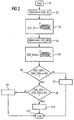
- FIG. 2 A flowchart of the program with which a first embodiment the exhaust gas recirculation system to the diagnostic device is monitored is shown in Figure 2.
- step S1 the program is started.
- a target value EGR_AV of the exhaust gas recirculation rate is determined.
- the pressure sensor 19 detects the intake manifold pressure MAP_MES and the observer 25 determines the observer intake manifold pressure MAP_MDL.
- the observer comprises only one model of the intake tract 1 of the internal combustion engine.
- the exhaust gas partial pressure which is proportional to an exhaust gas mass flow to the exhaust gas recirculation valve 10, is therefore not covered by this model.
- step S3 a target value EGR_SP of the exhaust gas recirculation rate read out from a permanently stored map KF1.
- Setpoints depend on one in the map KF1 Load size (e.g. an air mass flow at throttle valve 4) and the speed n and / or an engine temperature and / or one of the stroke course of the gas exchange valves of the internal combustion engine determining tax variable.
- a diagnostic value EGR_VER, EGR_DIF des Exhaust gas recirculation system determined. So the diagnostic value EGR_VER the ratio of the actual value EGR_AV and the setpoint Mapped to EGR_SP. Alternatively, you can also use the diagnostic value EGR_DIF is a difference between the actual value EGR_AV and the setpoint EGR_SP can be assigned.
- a diagnostic threshold EGR_DIAG read out from a second map KF2 and interpolated if necessary. Diagnostic threshold values are in the map KF2 EGR_DIAG permanently saved depending on at least an operating size of the internal combustion engine. It is beneficial if the diagnostic threshold values in the map KF2 in Dependence on a load size - e.g. the air mass flow on the throttle valve 4 or the opening angle of the throttle valve 4 and the speed n - and / or the ambient pressure and / or the exhaust gas temperature and / or the temperature in the Intake tract 1 and / or one of the stroke course of the gas exchange valves the control variable determining the internal combustion engine are filed.
- a load size e.g. the air mass flow on the throttle valve 4 or the opening angle of the throttle valve 4 and the speed n - and / or the ambient pressure and / or the exhaust gas temperature and / or the temperature in the Intake tract 1 and / or one of the stroke course of the gas exchange valves the control variable determining the internal combustion engine are
- a step S6 it is checked whether the diagnostic value of the exhaust gas recirculation system EGR_VER, EGR_DIF is greater than the diagnostic threshold EGR_DIAG plus a hysteresis value HYS.
- the Hysteresis value HYS is either fixed or dependent of at least one operating variable of the internal combustion engine. If the condition checked in step S6 is met, then in branches to step S7. The diagnostic device recognizes there 23 that the flow through the EGR return line 9 too is high. The program is then ended in step S11.
- step S6 If the condition checked in step S6 is not met, then the program branches to step S8 by checking whether the diagnostic value EGR_VER, EGR_DIF is less than the diagnostic threshold value EGR_DIAG minus the hysteresis value HYS. is if this is the case, the process branches to step S9, in which the Diagnostic device 23 the flow through the exhaust gas recirculation line 9 recognized as too low. The procedure is then in Step S11 ends.
- step S8 If the condition checked in step S8 is not fulfilled, then the program branches to step S10, in which it is recognized that the exhaust gas recirculation system works perfectly. Subsequently the program is ended in step S10.
- steps S6 and S8 it is checked whether the diagnostic value EGR_VER is outside a range of values lower limit of the diagnostic threshold EGR_DIAG minus that Hysteresis value and its upper limit the diagnostic threshold EGR_DIAG plus the hysteresis value. It is beneficial if the hysteresis value HYS depends on at least one Company size is determined.
- a program according to the flow chart is preferably in predetermined time intervals during the operation of the internal combustion engine started cyclically.
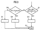
- step S8a branches if determined in the step S8 became that the diagnostic value EGR_VER, EGR_DIF smaller is as the diagnostic threshold EGR_DIAG minus the hysteresis value HYS is.
- step S8a it is checked whether the Actual EGR_AV value of the exhaust gas recirculation rate is plausible. For this becomes the actuator of the exhaust gas recirculation valve 10 by the control device 24 controlled such that the exhaust gas recirculation valve 10 closes.
- the exhaust gas recirculation valve 10 When the exhaust gas recirculation valve 10 is closed, it is then checked whether whether the diagnostic value EGR_VER is within a second value range whose upper limit is the sum of a second Diagnostic threshold value and the hysteresis value HYS are specified and its lower limit by the difference of one second diagnostic threshold value and the hysteresis value HYS is specified.
- step S9 in which, analogously to FIG insufficient flow through the exhaust gas recirculation line 9 detected becomes.
- step S9a If the actual value EGR_AV is not plausible in step S8, then branched to step S9a. A diagnosis is in this Step not possible because of an error in the electronic Motor controller 14 or one of the sensors is present. Possibly. here is another function to detect this error called. Then the program in step S11 completed.
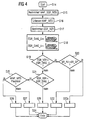
- an observer intake manifold pressure MAP_EGR_MDL determined. This observer intake manifold pressure MAP_EGR_MDL is in the observer 25 using a physical Model of intake system 1 and the exhaust gas recirculation system - as described above - determined.
- a step S16 the intake manifold pressure MAP_MES from the Pressure sensor 19 detected.
- the diagnostic value EGR_VER determined, here the ratio from the Manifold pressure MAP_MES and the observer manifold pressure MAP_EGR_MDL is assigned.
- an upper diagnostic threshold EGR_DIAG_U determined from a third map KF3 that depends of at least one operating variable of the internal combustion engine is, preferably dependent on an air mass flow, which is detected by the air mass meter 17a, and the speed n and / or the engine temperature and / or the stroke curve determining the gas exchange valves of the internal combustion engine Control variable. Furthermore, a lower one becomes in step S18 Diagnostic threshold EGR_DIAG_U from a map KF4 determined that is dependent on the air mass flow that Speed n and / or an engine temperature and / or an the stroke course of the gas exchange valves of the internal combustion engine determining tax figure.
- step S19 it is checked whether the diagnostic value EGR_VER is greater than the upper diagnostic threshold EGR_DIAG_U. If this is the case, then in step S20 branches in which a rough-running actual value ER_AV and a rough-running setpoint ER_SP can be determined.
- a procedure for Determining the uneven running actual value and setpoint ER_AV, ER_SP is in an older application from the same applicant ( WO 97/22786).
- step S20 It is then checked in step S20 whether the uneven running actual value ER_AV is greater than the rough running setpoint ER_SP. If this is the case, the process branches to step S22a, in which the diagnostic device 23 recognizes that the Flow through the exhaust gas recirculation line 9 is too high. Subsequently the program is ended in step S24.
- step S20 If the condition of step S20 is not fulfilled, then in branches to step S22, in which the diagnostic device 23 recognizes that the exhaust gas recirculation system is fault-free. The The program is then ended in step S24.
- step S19 the diagnostic value EGR_VER is not greater than the upper diagnostic threshold EGR_DIAG_U, is in the Step S 21 branches, in which it is checked whether the diagnostic value EGR_VER less than the lower diagnostic threshold EGR_DIAG_L is.
- step S25 in which is checked whether the intake manifold pressure MAP_MES is plausible is.
- the exhaust gas recirculation valve is closed and in accordance of steps S15 to S21 checks whether the diagnostic value EGR_VER is within the range of values whose lower Limit of the lower diagnostic threshold EGR_DIAG_L and its upper limit is the upper diagnostic threshold EGR_DIAG_U. If this is the case, the intake manifold pressure MAP_MES is plausible and the program branches to step S26, in which the diagnostic device 23 to an insufficient flow through the Exhaust gas recirculation line 9 recognizes.
- step S27 which corresponds to step S9a.
- the program will follow both Step S26 as well as after step S27 in step S24 ends.
- the embodiment of the diagnostic device described in FIG. 4 23 has the advantage that the diagnosis takes place in several stages and thus extremely precise results can be determined. With a perfectly functioning exhaust gas recirculation system the operation of the Internal combustion engine.
Description

Claims (10)
- Diagnoseeinrichtung (23) in einer elektronischen Motorsteuerung (14) für ein Abgasrückführ-System einer Brennkraftmaschine, wobei das Abgasrückführ-System eine Abgasrückführleitung (9) umfaßt, die einen Abgastrakt (8) mit einen Ansaugtrakt (1) verbindet und deren Öffnungsquerschnitt mittels eines Abgasrückführventils (10) einstellbar ist, wobei eine Steuereinrichtung (24) zum Steuern des Abgasrückführventils (10) vorgesehen ist und in dem Ansaugtrakt (1) ein Drucksensor (19) angeordnet ist, der einen Saugrohrdruck (MAP_MES) erfaßt, dadurch gekennzeichnet,daß sie Mittel aufweist zum Ermitteln eines Diagnosewertes (EGR_VER, EGR_DIF) des Abgasrückführ-Systems ohne ein Beeinflussen des Betriebs der Brennkraftmaschine, wobei der Diagnosewert (EGR_VER, EGR_DIF) abhängt von dem Saugrohrdruck (MAP_MES) und einem Beobachter-Saugrohrdruck (MAP_MDL, MAP_EGR_MDL), der durch einen Beobachter (25) aus mindestens einer weiteren Betriebsgröße der Brennkraftmaschine ermittelbar ist, unddaß sie Mittel aufweist zum Erkennen des Abgasrückführ-Systems als fehlerhaft, wenn der Diagnosewert (EGR_VER, EGR_DIF) außerhalb eines von mindestens einer Betriebsgröße abhängigen Wertebereichs liegt.
- Diagnoseeinrichtung nach Anspruch 1, dadurch gekennzeichnet, daß der Diagnosewert (EGR_VER) durch Bilden des Verhältnisses ermittelbar ist von dem Istwert (EGR_AV) zu dem Sollwert (EGR_SP) einer Abgasrückführrate.
- Diagnoseeinrichtung nach Anspruch 1, dadurch gekennzeichnet, daß der Diagnosewert (EGR_DIF) ermittelbar ist durch Bilden der Differenz zwischen dem Istwert (EGR_AV) und dem Sollwert (EGR_SP) einer Abgasrückführrate.
- Diagnoseeinrichtung nach Anspruch 2 oder 3, dadurch gekennzeichnet, daß der Sollwert aus einem Kennfeld ermittelbar ist, das abhängt von einer Lastgröße.
- Diagnoseeinrichtung nach Anspruch 3, dadurch gekennzeichnet, daß der Istwert (EGR_AV) nach der Beziehung
- Diagnoseeinrichtung nach Anspruch 1, dadurch gekennzeichnet, daß der Diagnosewert (EGR_VER) durch Bilden des Verhältnisses von dem Saugrohrdruck (MAP_MES) zu dem Beobachter-Saugrohrdruck (MAP_EGR_MDL) ermittelbar ist, und daß die Steuereinrichtung (24) den Beobachter (25) aufweist, der ein physikalisches Modell des Ansaugtraktes (1) und des Abgasrückführ-Systems umfaßt und der in Abhängigkeit von einem Öffnungswinkel einer Drosselklappe (4), dem Öffnungsgrad des Abgasrückführventils (10) und der Drehzahl (n) den Beobachter-Saugrohrdruck (MAP_EGR_MDL) ermittelt.
- Diagnoseeinrichtung nach Anspruch 1, dadurch gekennzeichnet, daß der Wertebereich durch einen Diagnoseschwellenwert (EGR_DIAG) und einen Hysteresewert (HYS) vorgegeben ist, daß der Diagnoseschwellenwert (EGR DIAG) aus einem Kennfeld ermittelbar ist, das abhängig ist von mindestens einer Betriebsgröße der Brennkraftmaschine.
- Diagnoseeinrichtung nach Anspruch 1, dadurch gekennzeichnet, daß die Mittel zum Erkennen des Abgasrückführ-Systems als fehlerhaft derart ausgebildet sind, daß ein zu hoher Massenstrom durch die Abgasrückführleitung (9) erkennbar ist, wenn der Diagnosewert (EGR_VER, EGR_DIF) über dem Wertebereich liegt und ein Laufunruhe-Sollwertes (ER_SP) überschritten wird.
- Diagnoseeinrichtung nach Anspruch 1, dadurch gekennzeichnet, daß die Mittel zum Erkennen des Abgasrückführ-Systems als fehlerhaft derart ausgebildet sind, daß wenn der Diagnosewert (EGR_VER, EGR_DIF) unter dem Wertebereich liegt, eine Plausibilitätsprüfung des Istwertes (EGR_AV) durchführbar ist, und daß bei einem plausiblen Istwert (EGR_AV) ein zu geringer Massenstrom durch die Abgasrückführleitung (9) erkennbar ist.
- Diagnoseeinrichtung nach Anspruch 9, dadurch gekennzeichnet, daß zur Plausibilitätsprüfung das Abgasrückführventil (10) schliessbar ist.
Applications Claiming Priority (3)
| Application Number | Priority Date | Filing Date | Title |
|---|---|---|---|
| DE19634975 | 1996-08-29 | ||
| DE19634975A DE19634975C1 (de) | 1996-08-29 | 1996-08-29 | Diagnoseeinrichtung zum Überwachen eines Abgasrückführsystems einer Brennkraftmaschine |
| PCT/DE1997/001803 WO1998009067A2 (de) | 1996-08-29 | 1997-08-20 | Diagnoseeinrichtung zum überwachen eines abgasrückführsystems einer brennkraftmaschine |
Publications (2)
| Publication Number | Publication Date |
|---|---|
| EP0922210A2 EP0922210A2 (de) | 1999-06-16 |
| EP0922210B1 true EP0922210B1 (de) | 2003-05-21 |
Family
ID=7804050
Family Applications (1)
| Application Number | Title | Priority Date | Filing Date |
|---|---|---|---|
| EP97941799A Expired - Lifetime EP0922210B1 (de) | 1996-08-29 | 1997-08-20 | Diagnoseeinrichtung zum überwachen eines abgasrückführsystems einer brennkraftmaschine |
Country Status (4)
| Country | Link |
|---|---|
| US (1) | US6044826A (de) |
| EP (1) | EP0922210B1 (de) |
| DE (2) | DE19634975C1 (de) |
| WO (1) | WO1998009067A2 (de) |
Families Citing this family (30)
| Publication number | Priority date | Publication date | Assignee | Title |
|---|---|---|---|---|
| DE19731420A1 (de) * | 1997-07-22 | 1999-01-28 | Bosch Gmbh Robert | Vorrichtung zur Erfassung des Drucks und der Temperatur im Saugrohr einer Brennkraftmaschine und Verfahren zu ihrer Herstellung |
| DE19849256A1 (de) * | 1998-10-26 | 2000-04-27 | Bosch Gmbh Robert | Verfahren und Vorrichtung zur Diagnose einer Abgasrückführung eines Verbrennungsprozesses |
| DE19941006A1 (de) * | 1999-08-28 | 2001-03-01 | Volkswagen Ag | Funktionsüberwachung eines Luftmassenregelsystems |
| JP2001304043A (ja) * | 2000-04-20 | 2001-10-31 | Hitachi Ltd | 排気ガス再循環装置の故障診断装置 |
| JP3535077B2 (ja) * | 2000-06-19 | 2004-06-07 | 本田技研工業株式会社 | 内燃機関の制御装置 |
| DE10118878A1 (de) * | 2001-04-18 | 2002-10-31 | Bosch Gmbh Robert | Verfahren zum Betreiben einer Brennkraftmaschine insbesondere eines Kraftfahrzeugs |
| US6708104B2 (en) | 2001-07-27 | 2004-03-16 | Detroit Diesel Corporation | Engine control based on exhaust back pressure |
| US6763708B2 (en) | 2001-07-31 | 2004-07-20 | General Motors Corporation | Passive model-based EGR diagnostic |
| JP2003155957A (ja) * | 2001-09-04 | 2003-05-30 | Mitsubishi Motors Corp | Egr制御装置及びegr制御方法 |
| US20060235629A1 (en) * | 2003-05-21 | 2006-10-19 | Walker Jeffrey S | Flow meter monitoring and data logging system |
| US6848418B1 (en) * | 2003-11-10 | 2005-02-01 | Ford Global Technologies, Llc | External exhaust gas recirculation on board diagnostic using EGR effect on a combination of engine operating parameters |
| US9147893B2 (en) | 2004-06-02 | 2015-09-29 | Toyota Jidosha Kabushiki Kaisha | Failure diagnostic device for discharge valve |
| DE102006012656A1 (de) * | 2006-03-20 | 2007-09-27 | Siemens Ag | Verfahren und Vorrichtung zum Betreiben einer Brennkraftmaschine |
| US7739027B2 (en) | 2007-08-17 | 2010-06-15 | Gm Global Technology Operations, Inc. | Method and apparatus for monitoring an EGR valve in an internal combustion engine |
| DE102007044937B4 (de) * | 2007-09-20 | 2010-03-25 | Continental Automotive Gmbh | Verfahren und Vorrichtung zum Betreiben einer Brennkraftmaschine |
| DE102007045264B4 (de) * | 2007-09-21 | 2012-10-04 | Continental Automotive Gmbh | Verfahren und Vorrichtung zum Betreiben einer Brennkraftmaschine |
| DE102008041804B4 (de) * | 2008-09-04 | 2020-06-25 | Robert Bosch Gmbh | Verfahren und Vorrichtung zur Überwachung einer Abgasrückführungsanordnung |
| GB2484297A (en) * | 2010-10-05 | 2012-04-11 | Gm Global Tech Operations Inc | A combustion engine evaluation unit comprising fault detection system for engine using EGR |
| KR20130063946A (ko) * | 2011-12-07 | 2013-06-17 | 현대자동차주식회사 | 배기가스 재순환 진단장치 및 배기가스 재순환 진단방법 |
| CN102840995B (zh) * | 2012-09-10 | 2015-03-25 | 临海市伟达汽车部件有限公司 | Egr冷却器性能测试分析系统 |
| US9422877B2 (en) * | 2013-10-11 | 2016-08-23 | General Electric Company | System and method for control of exhaust gas recirculation (EGR) utilizing process temperatures |
| FR3048455B1 (fr) * | 2016-03-04 | 2020-01-10 | Renault S.A.S. | Procede de diagnostic d'une vanne egr |
| KR20210069411A (ko) * | 2019-12-03 | 2021-06-11 | 현대자동차주식회사 | Egr 유량 진단 방법 |
| US11813926B2 (en) | 2020-08-20 | 2023-11-14 | Denso International America, Inc. | Binding agent and olfaction sensor |
| US11636870B2 (en) | 2020-08-20 | 2023-04-25 | Denso International America, Inc. | Smoking cessation systems and methods |
| US11760169B2 (en) | 2020-08-20 | 2023-09-19 | Denso International America, Inc. | Particulate control systems and methods for olfaction sensors |
| US11932080B2 (en) | 2020-08-20 | 2024-03-19 | Denso International America, Inc. | Diagnostic and recirculation control systems and methods |
| US11881093B2 (en) | 2020-08-20 | 2024-01-23 | Denso International America, Inc. | Systems and methods for identifying smoking in vehicles |
| US11760170B2 (en) | 2020-08-20 | 2023-09-19 | Denso International America, Inc. | Olfaction sensor preservation systems and methods |
| US11828210B2 (en) | 2020-08-20 | 2023-11-28 | Denso International America, Inc. | Diagnostic systems and methods of vehicles using olfaction |
Family Cites Families (6)
| Publication number | Priority date | Publication date | Assignee | Title |
|---|---|---|---|---|
| JP2586205B2 (ja) * | 1990-11-07 | 1997-02-26 | 三菱電機株式会社 | 排気ガス還流制御装置の故障診断装置 |
| DE4216044C2 (de) * | 1992-05-15 | 2001-03-15 | Bosch Gmbh Robert | Abgasrückführungs-Diagnosesystem an einem Verbrennungsmotor |
| JP2881075B2 (ja) * | 1992-08-05 | 1999-04-12 | 三菱電機株式会社 | 排気還流制御装置の故障診断方法 |
| JPH06264827A (ja) * | 1993-03-10 | 1994-09-20 | Nissan Motor Co Ltd | Egr制御装置 |
| US5508926A (en) * | 1994-06-24 | 1996-04-16 | General Motors Corporation | Exhaust gas recirculation diagnostic |
| JP2870418B2 (ja) * | 1994-09-30 | 1999-03-17 | 三菱自動車工業株式会社 | 排気ガス再循環装置の故障診断装置 |
-
1996
- 1996-08-29 DE DE19634975A patent/DE19634975C1/de not_active Expired - Fee Related
-
1997
- 1997-08-20 EP EP97941799A patent/EP0922210B1/de not_active Expired - Lifetime
- 1997-08-20 DE DE59710135T patent/DE59710135D1/de not_active Expired - Lifetime
- 1997-08-20 WO PCT/DE1997/001803 patent/WO1998009067A2/de active IP Right Grant
-
1999
- 1999-03-01 US US09/259,640 patent/US6044826A/en not_active Expired - Fee Related
Also Published As
| Publication number | Publication date |
|---|---|
| WO1998009067A2 (de) | 1998-03-05 |
| WO1998009067A3 (de) | 1998-04-16 |
| US6044826A (en) | 2000-04-04 |
| DE59710135D1 (de) | 2003-06-26 |
| DE19634975C1 (de) | 1998-04-16 |
| EP0922210A2 (de) | 1999-06-16 |
Similar Documents
| Publication | Publication Date | Title |
|---|---|---|
| EP0922210B1 (de) | Diagnoseeinrichtung zum überwachen eines abgasrückführsystems einer brennkraftmaschine | |
| DE102007013250B4 (de) | Verfahren und Vorrichtung zum Betreiben einer Brennkraftmaschine mit mindestens einem Zylinder | |
| DE102010044164B4 (de) | Verfahren und Vorrichtung zur Steuerung einer Brennkraftmaschine | |
| DE102007009689B4 (de) | Verfahren zum Betreiben einer Brennkraftmaschine mit Abgasrückführung | |
| EP1115964B1 (de) | Verfahren zum steuern einer brennkraftmaschine abhängig von einem abgasdruck | |
| DE102008000691A1 (de) | Verfahren und Vorrichtung zur Überwachung eines Zuluftsystems einer Brennkraftmaschine | |
| DE102016219781A1 (de) | Verfahren und Steuergerät zum Abgleich und zur Diagnose eines Abgasrückführmassenstrommessers | |
| EP1305514B1 (de) | Verfahren zur diagnose der funktionstüchtigkeit eines abgasrückführungssystems einer brennkraftmaschine | |
| DE102008040857B4 (de) | Steuergerät und Informationserlangungsgerät für ein Abgassystem einer Brennkraftmaschine | |
| DE19515382C2 (de) | Diagnosevorrichtung und -verfahren für ein Verdunstungs-Spülsystem | |
| WO2019120904A1 (de) | Verfahren und vorrichtung zum bestimmen des verschmutzungsgrades eines luftfilters einer verbrennungskraftmaschine | |
| DE19627644C2 (de) | Verfahren und Vorrichtung zur Diagnose einer Auspuffgas-Rückführeinheit einer Brennkraftmaschine mit innerer Verbrennung | |
| EP1242739B1 (de) | Verfahren zur erkennung einer fehlfunktion bei einem sensor | |
| DE4203235A1 (de) | Ausfalldiagnosevorrichtung einer abgas-rueckfuehrungs-(agr)-steuereinrichtung | |
| DE102022104858A1 (de) | Verfahren und systeme für ein agr-system | |
| DE10038258C2 (de) | Verfahren zum Überprüfen der Funktionstüchtigkeit eines Abgasrückführungssystems einer Brennkraftmaschine | |
| DE102009055120B4 (de) | Verfahren zum Überprüfen einer Funktion eines Aktuators bzw. eines Sensors, Verfahren zum Kalibrieren eines Aktuators bzw. eines Sensors sowie entsprechende Vorrichtung | |
| DE4216044C2 (de) | Abgasrückführungs-Diagnosesystem an einem Verbrennungsmotor | |
| WO2008152037A1 (de) | Verfahren und vorrichtung zum überprüfen eines abgasrückführsystems und computerprogramm | |
| EP1362173B1 (de) | Verfahren zum ermitteln eines schätzwertes eines massenstroms in den ansaugtrakt einer brennkraftmaschine | |
| EP2076667A1 (de) | Verfahren und vorrichtung zur überwachung eines kraftstoffeinspritzsystems | |
| DE102007050299B4 (de) | Verfahren zur Überprüfung der Funktion eines Bypassventils | |
| EP0928366B1 (de) | Sekundärluftsystem für eine brennkraftmaschine | |
| DE602004004487T2 (de) | Diagnostisches Verfahren zur Feststellung von Fehlern in einem Luftzufuhrsystem für Verbrennungskraftmaschinen | |
| EP1249589B1 (de) | Verfahren und Vorrichtung zur Funktionsprüfung eines Bypasselements |
Legal Events
| Date | Code | Title | Description |
|---|---|---|---|
| PUAI | Public reference made under article 153(3) epc to a published international application that has entered the european phase |
Free format text: ORIGINAL CODE: 0009012 |
|
| 17P | Request for examination filed |
Effective date: 19990219 |
|
| AK | Designated contracting states |
Kind code of ref document: A2 Designated state(s): DE FR GB SE |
|
| 17Q | First examination report despatched |
Effective date: 20010724 |
|
| RIC1 | Information provided on ipc code assigned before grant |
Free format text: 7G 01M 15/00 A, 7F 02M 25/07 B |
|
| GRAH | Despatch of communication of intention to grant a patent |
Free format text: ORIGINAL CODE: EPIDOS IGRA |
|
| GRAH | Despatch of communication of intention to grant a patent |
Free format text: ORIGINAL CODE: EPIDOS IGRA |
|
| GRAA | (expected) grant |
Free format text: ORIGINAL CODE: 0009210 |
|
| AK | Designated contracting states |
Designated state(s): DE FR GB SE |
|
| REG | Reference to a national code |
Ref country code: GB Ref legal event code: FG4D Free format text: NOT ENGLISH |
|
| REF | Corresponds to: |
Ref document number: 59710135 Country of ref document: DE Date of ref document: 20030626 Kind code of ref document: P |
|
| GBT | Gb: translation of ep patent filed (gb section 77(6)(a)/1977) | ||
| PG25 | Lapsed in a contracting state [announced via postgrant information from national office to epo] |
Ref country code: SE Free format text: LAPSE BECAUSE OF FAILURE TO SUBMIT A TRANSLATION OF THE DESCRIPTION OR TO PAY THE FEE WITHIN THE PRESCRIBED TIME-LIMIT Effective date: 20030821 |
|
| ET | Fr: translation filed | ||
| PLBE | No opposition filed within time limit |
Free format text: ORIGINAL CODE: 0009261 |
|
| STAA | Information on the status of an ep patent application or granted ep patent |
Free format text: STATUS: NO OPPOSITION FILED WITHIN TIME LIMIT |
|
| 26N | No opposition filed |
Effective date: 20040224 |
|
| PGFP | Annual fee paid to national office [announced via postgrant information from national office to epo] |
Ref country code: FR Payment date: 20080813 Year of fee payment: 12 |
|
| PGFP | Annual fee paid to national office [announced via postgrant information from national office to epo] |
Ref country code: GB Payment date: 20080821 Year of fee payment: 12 |
|
| GBPC | Gb: european patent ceased through non-payment of renewal fee |
Effective date: 20090820 |
|
| REG | Reference to a national code |
Ref country code: FR Ref legal event code: ST Effective date: 20100430 |
|
| PG25 | Lapsed in a contracting state [announced via postgrant information from national office to epo] |
Ref country code: FR Free format text: LAPSE BECAUSE OF NON-PAYMENT OF DUE FEES Effective date: 20090831 |
|
| PG25 | Lapsed in a contracting state [announced via postgrant information from national office to epo] |
Ref country code: GB Free format text: LAPSE BECAUSE OF NON-PAYMENT OF DUE FEES Effective date: 20090820 |
|
| PGFP | Annual fee paid to national office [announced via postgrant information from national office to epo] |
Ref country code: DE Payment date: 20140831 Year of fee payment: 18 |
|
| REG | Reference to a national code |
Ref country code: DE Ref legal event code: R119 Ref document number: 59710135 Country of ref document: DE |
|
| PG25 | Lapsed in a contracting state [announced via postgrant information from national office to epo] |
Ref country code: DE Free format text: LAPSE BECAUSE OF NON-PAYMENT OF DUE FEES Effective date: 20160301 |