EP0921782B1 - Sanitär- und schalensystem für wirbelbecken - Google Patents
Sanitär- und schalensystem für wirbelbecken Download PDFInfo
- Publication number
- EP0921782B1 EP0921782B1 EP97933464A EP97933464A EP0921782B1 EP 0921782 B1 EP0921782 B1 EP 0921782B1 EP 97933464 A EP97933464 A EP 97933464A EP 97933464 A EP97933464 A EP 97933464A EP 0921782 B1 EP0921782 B1 EP 0921782B1
- Authority
- EP
- European Patent Office
- Prior art keywords
- water
- shell
- jet
- channel
- containment
- Prior art date
- Legal status (The legal status is an assumption and is not a legal conclusion. Google has not performed a legal analysis and makes no representation as to the accuracy of the status listed.)
- Expired - Lifetime
Links
- 238000009428 plumbing Methods 0.000 title description 9
- XLYOFNOQVPJJNP-UHFFFAOYSA-N water Substances O XLYOFNOQVPJJNP-UHFFFAOYSA-N 0.000 claims abstract description 163
- 230000035515 penetration Effects 0.000 claims abstract description 46
- 238000003287 bathing Methods 0.000 claims abstract description 25
- 238000009826 distribution Methods 0.000 claims abstract description 14
- 238000004891 communication Methods 0.000 claims abstract description 8
- 230000002093 peripheral effect Effects 0.000 claims description 24
- 239000006260 foam Substances 0.000 description 28
- 230000008439 repair process Effects 0.000 description 22
- 238000010276 construction Methods 0.000 description 13
- 239000000463 material Substances 0.000 description 6
- 238000000034 method Methods 0.000 description 6
- 230000006378 damage Effects 0.000 description 5
- 238000013461 design Methods 0.000 description 5
- 230000000149 penetrating effect Effects 0.000 description 4
- 238000001914 filtration Methods 0.000 description 3
- 239000004033 plastic Substances 0.000 description 3
- 229920003023 plastic Polymers 0.000 description 3
- CBENFWSGALASAD-UHFFFAOYSA-N Ozone Chemical compound [O-][O+]=O CBENFWSGALASAD-UHFFFAOYSA-N 0.000 description 2
- 230000000712 assembly Effects 0.000 description 2
- 238000000429 assembly Methods 0.000 description 2
- 230000008901 benefit Effects 0.000 description 2
- 239000002131 composite material Substances 0.000 description 2
- 230000002950 deficient Effects 0.000 description 2
- 238000009413 insulation Methods 0.000 description 2
- 238000005086 pumping Methods 0.000 description 2
- 239000000565 sealant Substances 0.000 description 2
- 238000007789 sealing Methods 0.000 description 2
- 125000000391 vinyl group Chemical group [H]C([*])=C([H])[H] 0.000 description 2
- 229920002554 vinyl polymer Polymers 0.000 description 2
- 230000000007 visual effect Effects 0.000 description 2
- 238000003466 welding Methods 0.000 description 2
- ZAMOUSCENKQFHK-UHFFFAOYSA-N Chlorine atom Chemical compound [Cl] ZAMOUSCENKQFHK-UHFFFAOYSA-N 0.000 description 1
- 241000238634 Libellulidae Species 0.000 description 1
- XUIMIQQOPSSXEZ-UHFFFAOYSA-N Silicon Chemical compound [Si] XUIMIQQOPSSXEZ-UHFFFAOYSA-N 0.000 description 1
- 238000009825 accumulation Methods 0.000 description 1
- 239000000654 additive Substances 0.000 description 1
- 239000000853 adhesive Substances 0.000 description 1
- 230000001070 adhesive effect Effects 0.000 description 1
- 230000009286 beneficial effect Effects 0.000 description 1
- 230000008859 change Effects 0.000 description 1
- 238000006243 chemical reaction Methods 0.000 description 1
- 229910052801 chlorine Inorganic materials 0.000 description 1
- 239000000460 chlorine Substances 0.000 description 1
- 238000004140 cleaning Methods 0.000 description 1
- 150000001875 compounds Chemical class 0.000 description 1
- 238000007796 conventional method Methods 0.000 description 1
- 230000008878 coupling Effects 0.000 description 1
- 238000010168 coupling process Methods 0.000 description 1
- 238000005859 coupling reaction Methods 0.000 description 1
- 238000005520 cutting process Methods 0.000 description 1
- 238000005034 decoration Methods 0.000 description 1
- 230000007547 defect Effects 0.000 description 1
- 238000001514 detection method Methods 0.000 description 1
- 238000011161 development Methods 0.000 description 1
- 238000003745 diagnosis Methods 0.000 description 1
- 230000000694 effects Effects 0.000 description 1
- 230000008030 elimination Effects 0.000 description 1
- 238000003379 elimination reaction Methods 0.000 description 1
- 239000000835 fiber Substances 0.000 description 1
- 239000011152 fibreglass Substances 0.000 description 1
- 238000005187 foaming Methods 0.000 description 1
- 230000005484 gravity Effects 0.000 description 1
- 238000010438 heat treatment Methods 0.000 description 1
- 238000002169 hydrotherapy Methods 0.000 description 1
- 230000001771 impaired effect Effects 0.000 description 1
- 238000001746 injection moulding Methods 0.000 description 1
- 238000009434 installation Methods 0.000 description 1
- 238000012423 maintenance Methods 0.000 description 1
- 229910052751 metal Inorganic materials 0.000 description 1
- 239000002184 metal Substances 0.000 description 1
- 150000002739 metals Chemical class 0.000 description 1
- 238000012986 modification Methods 0.000 description 1
- 230000004048 modification Effects 0.000 description 1
- 238000000465 moulding Methods 0.000 description 1
- 239000007800 oxidant agent Substances 0.000 description 1
- 238000004023 plastic welding Methods 0.000 description 1
- 230000002265 prevention Effects 0.000 description 1
- 230000008569 process Effects 0.000 description 1
- 230000004044 response Effects 0.000 description 1
- 230000000284 resting effect Effects 0.000 description 1
- 239000012812 sealant material Substances 0.000 description 1
- 229910052710 silicon Inorganic materials 0.000 description 1
- 239000010703 silicon Substances 0.000 description 1
- 229910001220 stainless steel Inorganic materials 0.000 description 1
- 239000010935 stainless steel Substances 0.000 description 1
- 239000013589 supplement Substances 0.000 description 1
- 235000019640 taste Nutrition 0.000 description 1
- 230000001225 therapeutic effect Effects 0.000 description 1
- 238000012549 training Methods 0.000 description 1
- 238000007666 vacuum forming Methods 0.000 description 1
Images


Classifications
-
- A—HUMAN NECESSITIES
- A61—MEDICAL OR VETERINARY SCIENCE; HYGIENE
- A61H—PHYSICAL THERAPY APPARATUS, e.g. DEVICES FOR LOCATING OR STIMULATING REFLEX POINTS IN THE BODY; ARTIFICIAL RESPIRATION; MASSAGE; BATHING DEVICES FOR SPECIAL THERAPEUTIC OR HYGIENIC PURPOSES OR SPECIFIC PARTS OF THE BODY
- A61H33/00—Bathing devices for special therapeutic or hygienic purposes
- A61H33/0087—Therapeutic baths with agitated or circulated water
-
- A—HUMAN NECESSITIES
- A61—MEDICAL OR VETERINARY SCIENCE; HYGIENE
- A61H—PHYSICAL THERAPY APPARATUS, e.g. DEVICES FOR LOCATING OR STIMULATING REFLEX POINTS IN THE BODY; ARTIFICIAL RESPIRATION; MASSAGE; BATHING DEVICES FOR SPECIAL THERAPEUTIC OR HYGIENIC PURPOSES OR SPECIFIC PARTS OF THE BODY
- A61H33/00—Bathing devices for special therapeutic or hygienic purposes
- A61H33/60—Components specifically designed for the therapeutic baths of groups A61H33/00
- A61H33/6005—Special constructive structural details of the bathtub, e.g. of the walls or supporting structure
-
- A—HUMAN NECESSITIES
- A61—MEDICAL OR VETERINARY SCIENCE; HYGIENE
- A61H—PHYSICAL THERAPY APPARATUS, e.g. DEVICES FOR LOCATING OR STIMULATING REFLEX POINTS IN THE BODY; ARTIFICIAL RESPIRATION; MASSAGE; BATHING DEVICES FOR SPECIAL THERAPEUTIC OR HYGIENIC PURPOSES OR SPECIFIC PARTS OF THE BODY
- A61H33/00—Bathing devices for special therapeutic or hygienic purposes
- A61H33/60—Components specifically designed for the therapeutic baths of groups A61H33/00
- A61H33/601—Inlet to the bath
- A61H33/6021—Nozzles
- A61H33/6063—Specifically adapted for fitting in bathtub walls
-
- A—HUMAN NECESSITIES
- A61—MEDICAL OR VETERINARY SCIENCE; HYGIENE
- A61H—PHYSICAL THERAPY APPARATUS, e.g. DEVICES FOR LOCATING OR STIMULATING REFLEX POINTS IN THE BODY; ARTIFICIAL RESPIRATION; MASSAGE; BATHING DEVICES FOR SPECIAL THERAPEUTIC OR HYGIENIC PURPOSES OR SPECIFIC PARTS OF THE BODY
- A61H2201/00—Characteristics of apparatus not provided for in the preceding codes
- A61H2201/01—Constructive details
- A61H2201/0107—Constructive details modular
-
- A—HUMAN NECESSITIES
- A61—MEDICAL OR VETERINARY SCIENCE; HYGIENE
- A61H—PHYSICAL THERAPY APPARATUS, e.g. DEVICES FOR LOCATING OR STIMULATING REFLEX POINTS IN THE BODY; ARTIFICIAL RESPIRATION; MASSAGE; BATHING DEVICES FOR SPECIAL THERAPEUTIC OR HYGIENIC PURPOSES OR SPECIFIC PARTS OF THE BODY
- A61H2201/00—Characteristics of apparatus not provided for in the preceding codes
- A61H2201/16—Physical interface with patient
- A61H2201/1683—Surface of interface
- A61H2201/1685—Surface of interface interchangeable
Definitions
- the present invention relates to a bathing system comprising a water distribution system as defined in the preamble of claim 1.
- a bathing system of this type is described in US-A-4,339,833.
- This document describes a hydro-massage apparatus comprising a shell having attached thereto a plurality of housings for receiving hydro-jet nozzles.
- the nozzles are connected to the containment of the shell via an opening covered by a screen, and are connected to the water supply lines by couplings extending through the wall of the housing.
- the water supply lines are arranged on the outside of the shell, i.e. at a location where usually an insolating material is to be arranged.
- spas Bathing appliances in the nature of spas, or so-called hot tubs, have become commercially successful.
- These spas are typically constructed as a molded shell to form a water containment, with seats, footwells, platforms for reclining, and the like molded into the shape of the shell.
- the shell is usually molded from plastic or fiberglass or a composite thereof.
- a pump or pumps usually placed in a chamber under the shell draw water from the water containment and reinject the water into the containment through a variety of nozzles, hydrotherapy jets, and the like.
- the jets are usually mounted in the shell under the water line, and are designed to provide a comforting or therapeutic effect to a person in the spa.
- the jets are usually mounted by making a hole in the shell, and fixing the jet in the hole by a use of seals, adhesives, welding compounds, or a combination thereof.
- Water supply lines from the pumps to the jets are usually flexible tubing or rigid PVC tubing. After the jets and tubing are in place, an expandable foaming polymeric material is blown into the empty spaces to provide thermal and sound insulation. This construction system has been used widely and successfully, and is currently almost universally used.
- the second serious problem is the detection of the source of leaks and their repair.
- the tubing, plumbing, jet and manifold connections, and the like, are usually buried in the foam covering the underside of the shell.
- the spa To access a leak, the spa must be emptied and turned on its side.
- the foam must then be dug out to access the leaking jets or connections. Since, the leak cannot be directly observed it must often be diagnosed by tracing the track of the leak through wet foam (sometimes by using a dye in the water), or by observing other signs of leakage or water damage. This is an imprecise process and can result in unnecessary misdiagnosed or precautionary repairs.
- the complexity of the jet and plumbing designs creates a "spaghetti bowl" of tubing which can render access to a particular jet or joint nearly impossible.
- removal and replacement of the defective component often involves cutting out and removing the welds or seals of the part with the shell, and then replacing them with new parts.
- the old jet must often be cut out and removed from the water connection.
- the old sealant materials must be scraped off from surfaces around the hole in the shell.
- the new jet must then be resealed to the shell hole, and the water connections resealed rewelded, or spliced into place.
- the water When a leak does occur, it is important that the leak be repaired soon, for a leak can lead to further damage of spa components, and to the surroundings of the spa.
- the water when leaking water soaks into and saturates the insulating foam, the water substantially reduces the R-value of the foam. This can substantially increase the energy costs for heating the water.
- the present systems are prone to leaks at nearly inaccessible, difficult to reach locations.
- the leaks are often difficult to diagnose, and the repair is costly and labor intensive.
- the difficultly in replacing jets precludes any real flexibility on the part of the spa owner in adapting the spa and its jet designs and types to his own individual interests.
- the present invention overcomes or substantially alleviates the aforesaid problems of prior-art systems.
- a distribution system within the containment that allows withdrawal or introduction of water from a plurality of points but with one shell penetration.
- the distribution system is contained in a hollow which is formed into the spa shell as a pod depression with channel.
- the hollow is covered to present a smooth surface inside the containment. Accordingly, unsightly and unsafe plumbing and the like are not exposed to the bather.
- the hollows are appropriately shaped to enclose piping, nozzles, or the like.
- a water distribution line penetrates the spa shell at only one point and the water supply lines are contained in the channels, which lead to multiple jets that are mounted on covers that cover or enclose the pods.
- the water distribution system for a spa has a channel extending around at least a portion of the peripheral edge of the shell of the spa.
- a water feed line extends along the bottom of the channel, penetrating the shell only at one or both ends of the channel above the standard fill line or operating water level of the spa.
- the water feed line is connected to a pressurized water source, usually the recirculation pump of the spa.
- a depression or jet pod is molded into the shell, interrupting the channel with the peripheral water feed line extending across the pod.
- the peripheral feed line is provided with suitable water outlets, such as through a manifold construction, to provide water supply to jets in the pod.
- the water outlets are connected to the jets by suitable means, such as flexible jet feed lines, which are preferably mounted upon a jet plate or cover that covers the pod depression and provides an enclosure for the manifold and jet supply lines.
- the manifold preferably comprises union connectors that permit removal of the manifold from the supply line, along with associated jets and lines supplying the jets. This permits easy replacement, upgrade, and repair of the jets.
- the number of penetrations of the shell is kept to a minimum, which minimizes the occurrence of leaks through the shell.
- Most of the water supply circuit, particularly vulnerable connections and manifolds to jets, are on the containment side of the shell, so that if there is a leak, water will flow harmlessly into the containment. This contrasts with prior-art systems where there are several penetrations, at least one for each jet, and the water supply system is mostly buried in foam on the underside of the shell.
- the benefit of the present invention is the low occurrence of leaks, the elimination of the possibility of damage for most leaks that may occur, and the ease of repairing, modifying and upgrading the system.
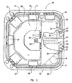
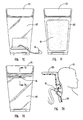
- FIG 1 is a perspective view of a spa of the invention 101 comprising a shell 103 to provide a containment 105 for water, and a skirt cabinet 107 that conceals the support structure 108 and insulating foam 110 for the shell, and the pumping, filtration and circulation hardware.
- the spa 101 illustrated is approximately 2,438 m (8 feet) square and 0,914 (3 feet) high.
- the shell is configured to comprise a lounging platform 109, a seating platform 111, and a footwell 113.
- the spa includes jets 115 through which water is directed under pressure into the containment 105. Drains 117 are provided to withdraw water from the containment for recirculation to the jets 115.
- a cover 119 is provided for access to the filter, and a touch pad control 121 is used to control the various functions of the spa.
- FIG 3 is a top view of the spa of Figure 1 in partial cutaway showing the plumbing system of the spa
- water is withdrawn from the containment through drains 117 and drain lines 123 by pumps 125.
- the water may be merely drawn out by gravity.
- a switching valve (not shown) may be provided to allow emptying of the containment by using the pumps.
- Pressurized water from the pumps 125 is directed through pump outlet lines 127 into peripheral supply lines 129.
- the peripheral supply lines 129 are disposed in a channel or channels 131 near the peripheral edge 133 of the shell, penetrating the shell 103 at a channel dam or dams 135 at an end of the channel 131.
- the channel 131 is interrupted at spaced, predetermined locations by a pod 137, which, as described further below, provides a containment and support for the jets 115.
- the pods 137 interrupt the channel 131 in such a manner to provide communication of the channel 131 with the containment 105, i.e., such that water in the channel 131 flows into the containment 105.
- the channel is constructed such that any water that may leak into the channel will eventually flow into the containment. This may be accomplished by providing water flow paths thought the channels into the pods as illustrated.
- the peripheral channels may be in or at the top of the side walls or in the floor of the shell so that water flows directly into the containment from the channel. If at the top of the side wall, the channel may then be covered with a quarter-round cover to conceal the supply lines in the channel.
- the channel may extend from the penetration of the channel through the shell and then travel, at least in part, under the water line.
- the channels would be in the form of grooves in the shell wall, with covers to enclose the water supply lines in the groove and present a generally continuous surface with the shell.
- This construction may be adaptable for jets, such as foot thrust jets, that are mounted near or in the bottom of the shell.
- the shell may have a full or partial false bottom, where a channel or channels with a water line or lines expand at the bottom into a jet pod hollow.
- a cover over the jet pod provides a false bottom surface and mount for bottom mounted jets.
- Further channels may extend from the bottom pods to additional bottom pods or up the sides of the shell to side mounted jets.
- additional channels extending from side jet pods, from the peripheral channel, or directly from the penetration may be used in place of or as a supplement to the peripheral channel.
- the invention derives its advantages from 1) having only a single penetration for a multiple set of jets, and 2) having the supply lines in covered channels, hollows or chambers that are disposed such that water will drain or flow into the containment. If the hollow is under the water-line 195 the hollow is merely in communication with the containment such that water flows freely between the hollow and the containment. If the hollow is above the water line, the hollow is constructed such that water flows into an adjacent hollow, channel, pod, or chamber, or directly into the containment.
- the penetration is preferably above the water line, but may also be below the water line. Since the line at the shell penetration will rarely require replacement or repair, the line and the shell can be permanently sealed at the penetration by welding or the like.
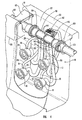
- the peripheral supply line 129 is supported in the channel 131.
- the channel is interrupted by a pod 137 which is molded into the shell 103 as a cavity or depression.
- the peripheral supply line 129 travels unsupported through the upper portion of the pod 137, and at this location includes a manifold 139 that provides one or more ports 147 for jet supply lines 141 that feed one or more jets 115 mounted in the pod.
- the manifold 139 and the jet supply lines 141 may be of any suitable construction.
- the illustrated manifold is formed with a pipe section 143 from the same pipe material as the peripheral supply line with a sleeve 145 covering the pipe section 143.
- the sleeve 145 is molded with one or more ports 147 for connection to flexible jet supply lines 141 that supply pressurized water to jets 115.
- the jets 115 illustrated are of conventional construction and comprise an air inlet 151 and water inlet 153.
- the jet 115 mixes air and water that are directed into a single pressurized steam into the containment.
- the water and air inlets 153, 151 are shown on the side and the back of the jet, respectively, but the jet may also be configured differently, for example with both ports on the side, or back.
- the air inlet 151 of each jet 115 is connected via air supply lines 155 to an air intake manifold/filter 157.
- union connectors 159 which allow disconnection and removal of the assembly 161 of the manifold 139, associated jets 115, and jet and air supply lines 141, 155, and air intake manifold 157. This allows easy replacement, maintenance, upgrading or repair of any components of the manifold/jet assembly 161.
- the present invention is particularly beneficial because of the response to leaks in the system. If there is a water leak of the peripheral supply line 129 where it extends through the channel 131, the water merely flows along the channel into an adjacent pod 137. If there is any leak associated with the manifold 139, jet supply lines 141, or jets 115, the water merely flows into the pod 137, which is essentially an extension with the water containment 105 of the shell 103. Thus, unless a leak at any of these points is severe, the leak will probably not even be detected, and will not materially compromise the function of the spa or jets. Thus, small leaks can continue without any harm to the spa system or knowledge to the user. In the case of a serious leak, such as a catastrophic failure of a jet or peripheral supply line, the water will merely flow into the channel or pod and eventually into the containment, and will not leak into and saturate the foam or harm other components of the spa.
- the peripheral supply lines are easily accessed in the channels, and the manifolds and jet supply lines are accessed from the containment in the pods.
- the shell where the supply line goes through the shell at the dam.
- this penetration there is a seal between the peripheral supply line and the shell to prevent leaks through the shell. Since the dam is usually above the water level of the containment, a failure of this seal may not even result in the leaking of water through the shell. Any water in the channel quickly flows out and into the pods, so there will be little water accumulation, if any, against the dam that might otherwise flow through a failed seal at the penetration.
- this penetration is preferably adjacent to the open chamber containing the pumping and filtering hardware. Therefore, access does not require removal of a thick layer of foam from underneath the spa, rather access is easily achieved though the open pump chamber.
- the channels may be covered for appearances by a cover 163. If access to the channel is required for repair of the peripheral supply line 129 or for cleaning, the cover 163 is merely removed. Thus, essentially the entire water supply circuit is accessible, without having to remove the water in the spa, opening the cabinet or tipping the spa up.
- the pumps and pump outlet lines are accessible though the open pump chamber, which may or may be not filled with foam.
- the peripheral supply lines are accessible through the channels, and the manifolds, jet supply lines, and jets are accessible through the pods.
- a repair often requires the removal of foam just to inspect a jet or supply line for secondary signs of leakage or a failure, which then is repeated until the actual leak is found.
- the result is unnecessary labor to access and inspect non-leaking components and frequently in unnecessary, precautionary repairs of non-leaking components.
- the components After the leak is repaired, the components must be allowed to dry, and new expandable foam applied, which also adds to the down time of the spa.
- each water supply circuit requires only one penetration of the shell, preferably above the water-line, to provide the water supply for many jets. This contrasts with the prior-art systems where there is an underwater penetration of the shell for each jet. Penetration sites of the shell are frequent sites for leakage through the shell, particularly where there is a penetration under the water line. Thus, in prior-art systems there are multiple under-water-line penetrations (one for each jet) of the shell for each water supply circuit, which in the present invention are replaced by one penetration.
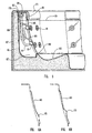
- FIG. 5 shown is a cross-section of a pod through 5-5 in Figure 2 showing the shell 103 and underlying foam 110.
- the jets 115 in the pod 137 are supported on a pod cover plate 165, which covers the cavity or depression forming the pod 137.
- the cover 165 is held in place by any appropriate means, such as that illustrated, a ridge 169 on the shell to engage the lower peripheral edge of the cover, and a shelf 170 at the top and front edge of the shell that supports the edges of the cover 165.
- Appropriate screws, clamps, clips or other fasteners may be used to further secure the cover in place.
- the attachment of the cover to the shell is preferably non-sealing with respect to water to permit free passage of water between the jet pod and the major containment of the shell.
- the cover may have apertures for the flow of water.
- the cover preferably includes a cushion or pillow 175 at its top edge for supporting the head of a bather.
- the cover 165 is preferably configured to provide a pleasing visual appearance and to provide a comfortable resting surface for the back of a bather. Accordingly, preferably the cover 165 also incorporates cushions 175, and the like for the comfort of the bather.
- the shell 103 and the cover 165 are configured so that there is a visual appearance of an essentially continuous surface. Since the manifold, and jet supply lines, etc., are covered in the pod by the cover, the only visible part is the jet outlet, and there are no projecting pipes or the like that would be unsightly or present a hazard. Visually speaking, essentially the only difference between the water containment of a spa of the invention and a prior art spa is the inconspicuous joints around the pod covers where they fit into the shell. As illustrated in Figures 6A and 6B, the cover 165 may also be optionally configured to provide ridges or contours 173 to provide decoration, or custom contours for lumbar back support.
- the jet-pack 161 which is the assembly of a cover 165 and jets 115 with associated jet air and jet supply lines 155, 141 and manifold 139, is easily removed from the spa. By simply removing any cushion 175 and any screw or fasteners holding the cover 165 in place, and disconnecting the union connectors 159 associated with the manifold 139, the jet-pack 161 can be removed. Alternately, the jet supply lines can be removed from their respective connection to the manifold instead of disconnecting the union connectors. The jet-pack can then be easily repaired, modified or upgraded, and then returned to the spa by reversal of the steps. The jet-pack can also be replaced by a new jet-pack of the same or a different configuration. Thus, a spa can be customized and modified at will by replacing any of the jets, with only a minimum of training and in only a short amount of time.
- the jets can be replaced without first emptying the spa.
- the replacement of jets in prior-art spas is difficult and the replacement with a different type of jet in many cases is difficult or impossible.
- Replacement of the jet in a prior-art spa, whether for repair or to change the type may involve the same laborious procedure involved in repairing leaks, i.e., tipping up the spa and removing the foam.
- a new jet must accommodate and be sealed into the existing penetration of the shell or the shell penetration must be modified. If the new jet requires a smaller penetration hole than the existing hole, it may not be practical or possible to seal the new jet into the shell penetration.
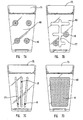
- Figures 7A through 7H show jet and cover assemblies with different jet and cover configurations. As discussed above, these covers are interchangeable, and any of these or similar assemblies can be mounted in a pod.
- Figure 7A shows a cover 165 with four conventional jets 115 directing pressurized water against the back of a bather leaning against the pod cover.
- Figure 7B shows the same conventional jets 115, but with slots 177.
- the edges of the slots engage grooves in the body of the jet to allow the jet to be moved to a new location by sliding it within the slot.
- Figure 7C also shows jets 115 that can be moved by sliding within slots 177, but the slots are vertical for vertical adjustment of the jets, and the jets are smaller.
- the sliding jet/slot arrangements in Figures 7B and 7C can be modified for any suitable slot arrangement and any size of jet.
- Figure 7D shows an integral cover/jet assembly where water is directed through numerous holes in the face of the cover with a pressurized cannister behind the face.
- Figure 7E shows a jet that is not mounted directly to the cover.
- the jet supply line is connected to a jet that merely lays unmounted in the pod containment. The user accesses the jet by opening a hinged panel, and pulling the jet though the passage.
- the jet supply line is of sufficient length to allow use of the jet as a wand, or the like.
- Figure 7F illustrates a cover 165 wherein the jet 115 is in the form of a foam pad through which pressurized water with air is directed out onto the back of the bather over the entire surface of the pad.
- the cover may also incorporate a vibrator that is powered by the pressure or flow of the water.
- Figures 7G and 7H illustrate a back massaging system wherein a jet or jets 115 are placed above the shoulder level of a bather to direct water down upon the neck and upper back of the bather 191.
- This configuration particularly illustrates the versatility of the invention.
- the cover is detachable, it can be vacuum formed with an undercut for an above-water-line jet to be angled down to prevent water splash from the spa.
- the undercut would have to be formed in the spa shell. Using conventional molding techniques this would be impossible as it would not permit removal of the shell from the mold.
- a downwardly directed jet would require a specialized multi-piece mold, or the like, which is difficult and expensive.
- Each of the covers illustrated in Figures 7A to 7H preferably includes a cushion or pillow at the top edge for supporting the head of a bather as he leans against the cover.
- the invention may be applied for every jet in a spa, or be selectively applied to only certain jets to create a hybrid system with conventional jets and jets in jet packs according to the invention.
- it may be more practical to mount jets in the floor, (such as the foot thruster 115A in Figure 3) in the conventional manner.
- the penetrations of the shell have been materially reduced and thus the inherent possibility of leaks reduced.
- the plumbing has been greatly simplified. Any conventionally mounted jets with shell penetrations and foam buried water supply lines can be mounted individually so access is not impaired by a confusion of supply lines for adjacent jets.
- the spa can be designed so that jets with shell penetrations are close to the pump chamber, requiring a minimum of water lines that are buried in foam under the shell. Even with a hybrid construction it is possible to have no water lines buried in foam.
- a jet supply system with a single shell penetration and with supply lines in covered channels, chambers or hollows in the side or bottom of the shell, the bottom, or under a false floor can be used to supply jets at any point within the shell.
- the penetration is always above the water line, but it is contemplated that a shell penetration may be below the water line.
- the water line at the penetration can be securely welded and reinforced to protect against leakage.
- under-water line penetrations for jets are usually sealed with silicon sealants to allow subsequent removal of the jet for a repair.
- the penetrating lines can be permanently welded to the shell.
- FIG 8 illustrates an application of the invention to a drain in a spa shell.
- the suction line to the pump is now required for safety reasons to have a plurality of redundant drain openings into the spa containment.
- the suction pressure at the opening has been found to be dangerous, in that it is sufficient to hold a child underwater by the hair, or suck out an eye of an overly curious child.
- a plurality of opening is required such that if an opening is blocked by a body part, hair, etc., there is sufficient flow from other drains to essentially eliminate any suction at the blocked opening.
- increasing the penetrations to create redundant drain openings increases the probability of leaks through the shell.
- each drain penetrates the shell at one point.
- Each point of penetration is recessed into a drain well 181, which is covered by well cover 183.
- Each drain well extends along a bottom edge of the footwell of the containment.
- Each well cover is perforated, as a screen, or has multiple apertures or drain openings for water passage. The effect is to spread the draining water over the entire surface or over several inlets in the well covers. Thus, there is drain opening redundancy for each drain line. Even though there is only one penetration of the shell by each drain line, the drain flow of each penetration is distributed over the surface of a wide well cover.
- a filter of suitable design (under filter cover 119) is provided to filter drained water before it enters the pump.
- the pump outlet lines, peripheral supply lines, and jet supply lines may be of any suitable tubing or piping, such as the conventional rigid and flexible lines, e.g., PVC piping and vinyl tubing used in spa construction.
- the manifolds may be of conventional design. They may be assembled from rigid piping or may be molded with suitable outlet ports.
- the jet water supply lines and air supply lines (if required) are preferably flexible tube materials conventionally used to ease installation and removal of the cover and the manifold.
- the attachment of the jet water supply lines to the ports of the manifold may be by any suitable means, such as hose clamps, or by a molded barbed fitting at the manifold port.
- the shell, pod covers and the like are preferably manufactured from plastic or plastic/fiber composite materials by conventional methods for spa shells, such as by vacuum forming or injection molding. Any other suitable material for the shells and covers is contemplated, for example, molded or stamped metals, such as stainless steel.
- the water distribution systems of the invention may also include other components for filtering or treating the water, water softeners and conditioners, ozone generators, chlorinators, skimmers, thermostat water heaters, and the like.
Landscapes
- Health & Medical Sciences (AREA)
- Public Health (AREA)
- Epidemiology (AREA)
- Pain & Pain Management (AREA)
- Physical Education & Sports Medicine (AREA)
- Rehabilitation Therapy (AREA)
- Life Sciences & Earth Sciences (AREA)
- Animal Behavior & Ethology (AREA)
- General Health & Medical Sciences (AREA)
- Veterinary Medicine (AREA)
- Nozzles (AREA)
- Devices For Medical Bathing And Washing (AREA)
- Tents Or Canopies (AREA)
- Sanitary Device For Flush Toilet (AREA)
- Vehicle Waterproofing, Decoration, And Sanitation Devices (AREA)
- External Artificial Organs (AREA)
- Pipeline Systems (AREA)
- Control For Baths (AREA)
- Percussion Or Vibration Massage (AREA)
- Jet Pumps And Other Pumps (AREA)
Claims (19)
- Badsystem mit einem Wasserverteilsystem, wobei das Badsystem eine einen Wasseraufnahmeraum (105) vorsehende Hülle (103) zum Aufnehmen von Wasser bis zu einer Betriebs-Wasserfüllstandslinie (195) umfasst, wobei das Wasserverteilsystem umfasst:mindestens eine Schalenmulde (137), die in die Hülle (103) eingeformt ist, die mit dem Aufnahmeraum (105) in Verbindung steht, derart, dass jedes Wasser in der Schalenmulde (137) in den Aufnahmeraum (105) fließen kann,mindestens eine Düse (115), die in der Schalenmulde (137) angeordnet ist, um Wasser in den Aufnahmeraum (105) zu leiten, mindestens eine Düsenzufuhrleitung (129, 141), die in der Schalenmulde (137) für mindestens einen Teil ihrer Länge angeordnet ist, undmindestens eine Abdeckung (163, 165), die so ausgebildet und konstruiert ist, dass sie mindestens einen Teil der mindestens einen Schalenmulde (137) bedeckt und ein Gehäuse für die mindestens eine Düsenzufuhrleitung (129, 141) bildet,dadurch gekennzeichnet,
dass die Düsenzufuhrleitung (129,141) sich von einer Durchdringung der Hülle (103) oberhalb der Betriebs-Wasserfüllstandslinie (195) des Aufnahmeraums (105) zu mindestens einer Düse (115) erstreckt, und ein Hohlraum vorgesehen ist, der die mindestens eine Schalenmulde (137) mit einem Kanal (131) umfasst, wobei der Kanal (131) sich von der Hüllendurchdringung zur Schalenmulde (137) erstreckt und so konstruiert ist, dass er in Verbindung mit dem Aufnahmeraum (105) steht, so dass das Wasser im Kanal (131) in den Aufnahmeraum (105) fließt. - Badsystem nach Anspruch 1, enthaltend eine Mehrzahl von Düsen (115) und eine Mehrzahl von Schalenmulden (137), die durch den mindestens einen Kanal (131) verbunden sind.
- Badsystem nach Anspruch 1, enthaltend eine einzige Schalenmulde (137) der Hülle (103) zum Verteilen des Wassers an eine Vielzahl von Düsen (115).
- Badsystem nach Anspruch 1, enthaltend mindestens zwei Wasserverteilsysteme mit getrennten Schalenmulden (137) der Hülle (103) und mit getrennten Düsenzufuhrleitungen, die in einem gemeinsamen Kanal angeordnet sind.
- Badsystem nach Anspruch 1, enthaltend mindestens zwei Wasserverteilsysteme mit getrennten Schalenmulden (137) der Hülle (103) und mit Düsenzufuhrleitungen, die in getrennten Kanälen angeordnet sind.
- Badsystem nach Anspruch 1, wobei die mindestens eine Düse (115) an der mindestens einen Abdeckung (165) montiert ist.
- Badsystem nach Anspruch 1, wobei der Kanal (131) sich teilweise unter der Betriebs-Wasserfüllstandslinie erstreckt.
- Badsystem nach Anspruch 1, wobei sich der gesamte Kanal (131) in seiner Gesamtheit oberhalb der Betriebswasserfüllstandslinie (195) erstreckt.
- Badsystem nach einem der Ansprüche 1 bis 8, umfassend eine geformte Hülle (103), um den Wasseraufnahmeraum (105) zu bilden, wobei
der mindestens eine Kanal (131) sich um mindestens einen Teil der Umfangskante (133) der Hülle (103) erstreckt,
die in Verbindung mit einer Druckwasserquelle (125) stehende Düsenzufuhrleitung (129) innerhalb des Kanals (131) angeordnet ist, mit einer Durchdringung der Hülle (103) durch die Düsenzufuhrleitung durch die Hülle in den Kanal,
wobei die mindestens eine Schalenmulde (137) im Aufnahmeraum (105) der Hülle (103) derart konstruiert und ausgebildet ist, dass der Kanal (131) durch die Schalenmulde (137) unterbrochen wird und sich die Düsenzufuhrleitung durch die Schalenmulde hindurch verlängert, und
die mindestens eine Wasserdüse (115) mit Wasserverbindung mit der Düsenzufuhrleitung in der Schalenmulde angeordnet ist. - Badsystem nach Anspruch 9, wobei die Durchdringung der Hülle (103) in den Kanal sich oberhalb der Betriebs-Wasserfüllstandslinie (195) und an einem Damm (135) an einem Ende des Kanals (131) befindet.
- Badsystem nach Anspruch 9, wobei die Abdeckung eine Abdeckplatte enthält und die Wasserdüse (115) an der Abdeckplatte (135) montiert ist, die die Schalenmulde (137) bedeckt.
- Badsystem nach Anspruch 9, wobei im Wesentlichen der gesamte Umfangskanal (131) sich oberhalb der Betriebs-Wasserfüllstandslinie (195) der Aufnahme (105) befindet.
- Badsystem nach Anspruch 9, wobei ein Teil des Umfangskanals (131) sich oberhalb der Betriebs-Wasserfüllstandslinie (195) der Aufnahme (105) am Damm (135) befindet, und sich ein Teil des Kanals (131) unterhalb der Betriebs-Wasserfüllstandslinie (195) erstreckt.
- Badsystem nach Anspruch 13, wobei der Teil des Kanals (131) unterhalb der Betriebs-Wasserfüllstandslinie (195) sich in eine Schalenmulde (137) an oder in der Nähe des Bodens der Hülle (103) erstreckt, wobei die Schalenmulde die mindestens eine Düse (115) enthält, die in der Abdeckung (165) über der Schalen mulde montiert ist, wobei die Abdeckung eine im Wesentlichen kontinuierliche Oberfläche innerhalb der Aufnahme zwischen der Hüllenoberfläche und der Abdeckungsoberfläche aufweist.
- Badsystem nach Anspruch 1 mit einer geformten Hülle, um eine Wasseraufnahme (105) darin auszubilden, wobei
sich der mindestens eine Kanal (131) um mindestens einen Teil der Umfangskante (133) der Hülle (103) erstreckt,
die Düsenzufuhrleitung (129, 141) in Verbindung mit einer Quelle (125) für Druckwasser entlang und innerhalb des Kanals (131) angeordnet ist, mit einer Durchdringung der Hülle (103) durch die Düsenzufuhrleitung durch einen Damm (135) an einem Ende des Kanals (131),
die mindestens eine Schalenmulde (137) in der Aufnahme (105) der Hülle (103) so konstruiert und ausgebildet ist, dass der Kanal (131) durch die Schalenmulde unterbrochen ist und die Düsenzufuhrleitung sich durch die Schalenmulde (137) hindurch fortsetzt,
ein Auslassförderverteiler (139) für Düsenwasser in der Düsenzufuhrleitung (129) nahe der Schalenmulde (137) vorgesehen ist, der so konstruiert und ausgebildet ist, dass er mindestens einen Wasserförderauslass für eine Düse (115) schafft, und
die mindestens eine Wasserdüse (115) in der Schalenmulde (137) mit einer Wasserverbindung mit dem Wasserförderauslass angeordnet ist. - Badsystem nach Anspruch 15, wobei die Düsenförderleitung am Verteiler (139) sich ununterstützt durch die Schalenmulde (137) erstreckt und Verbindungen umfasst, die ein Entfernen des Verteilers und den Ersatz mit dem gleichen Verteiler oder einem neuen Verteiler gestatten.
- Badsystem nach Anspruch 15, wobei die Druckwasserquelle eine Pumpe (125) ist, die Wasser aus der Aufnahme (105) durch eine Entwässerung (117) abzieht.
- Badsystem nach Anspruch 15, wobei die Abdeckung (165) die Schalenmulde (137) abdeckt, um ein Gehäuse für die Wasserauslassförderung zu schaffen.
- Badsystem nach Anspruch 18, wobei die Abdeckung (165) eine Einrichtung zum Montieren der mindestens einen Düse (115) bildet, und eine im Wesentlichen kontinuierliche Oberfläche zwischen der Oberfläche der Hülle (103) in der Aufnahme (105) und der Oberfläche der Abdeckung (165) bildet.
Priority Applications (1)
| Application Number | Priority Date | Filing Date | Title |
|---|---|---|---|
| EP07004603A EP1787621B1 (de) | 1996-07-10 | 1997-07-09 | Rohrleitungs- und Wannensystem für ein Strömungsbad |
Applications Claiming Priority (3)
| Application Number | Priority Date | Filing Date | Title |
|---|---|---|---|
| US677840 | 1996-07-10 | ||
| US08/677,840 US5754989A (en) | 1996-07-10 | 1996-07-10 | Plumbing and shell system for spa |
| PCT/US1997/012306 WO1998001098A1 (en) | 1996-07-10 | 1997-07-09 | Plumbing and shell system for spa |
Related Child Applications (1)
| Application Number | Title | Priority Date | Filing Date |
|---|---|---|---|
| EP07004603A Division EP1787621B1 (de) | 1996-07-10 | 1997-07-09 | Rohrleitungs- und Wannensystem für ein Strömungsbad |
Publications (3)
| Publication Number | Publication Date |
|---|---|
| EP0921782A1 EP0921782A1 (de) | 1999-06-16 |
| EP0921782A4 EP0921782A4 (de) | 2004-07-14 |
| EP0921782B1 true EP0921782B1 (de) | 2007-03-14 |
Family
ID=24720318
Family Applications (2)
| Application Number | Title | Priority Date | Filing Date |
|---|---|---|---|
| EP97933464A Expired - Lifetime EP0921782B1 (de) | 1996-07-10 | 1997-07-09 | Sanitär- und schalensystem für wirbelbecken |
| EP07004603A Expired - Lifetime EP1787621B1 (de) | 1996-07-10 | 1997-07-09 | Rohrleitungs- und Wannensystem für ein Strömungsbad |
Family Applications After (1)
| Application Number | Title | Priority Date | Filing Date |
|---|---|---|---|
| EP07004603A Expired - Lifetime EP1787621B1 (de) | 1996-07-10 | 1997-07-09 | Rohrleitungs- und Wannensystem für ein Strömungsbad |
Country Status (10)
| Country | Link |
|---|---|
| US (2) | US5754989A (de) |
| EP (2) | EP0921782B1 (de) |
| AT (2) | ATE445384T1 (de) |
| AU (1) | AU737335B2 (de) |
| CA (1) | CA2260237C (de) |
| DE (2) | DE69737477T2 (de) |
| DK (2) | DK0921782T3 (de) |
| ES (2) | ES2333267T3 (de) |
| NZ (1) | NZ334093A (de) |
| WO (1) | WO1998001098A1 (de) |
Families Citing this family (45)
| Publication number | Priority date | Publication date | Assignee | Title |
|---|---|---|---|---|
| US5987663A (en) * | 1996-07-10 | 1999-11-23 | Bullfrog International, L.C. | Modular system for spas and bathing systems |
| US5920923A (en) * | 1998-01-09 | 1999-07-13 | Jillette; Penn | Hydro-therapeutic stimulator |
| GB2349815A (en) * | 1999-03-11 | 2000-11-15 | Airbath Internat | Bath fitting to provide jets of air and/or water |
| US6957451B2 (en) | 1999-06-24 | 2005-10-25 | Saratoga Spa & Bath, Inc. | Flow control device for tub, spa, or shower |
| US6185757B1 (en) | 1999-06-24 | 2001-02-13 | Saratoga Spa & Bath Co., Inc. | Manual control of water delivery through ports of tub, spa or shower |
| US6490740B1 (en) | 1999-06-24 | 2002-12-10 | Saratoga Spa & Bath Co., Inc. | Motorized control of water delivery through ports of tub, spa or shower |
| US6899357B2 (en) * | 2001-03-12 | 2005-05-31 | Alpha-Western Corporation | Fitting and pipe section for jetted bath heaters |
| US20020125715A1 (en) * | 2001-03-12 | 2002-09-12 | Alpha-Western Corporation Dba Aquatemp Products Corporation | Fitting and pipe section for jetted bath heaters |
| DE10114356A1 (de) * | 2001-03-22 | 2002-09-26 | Hansgrohe Ag | Sanitäreinrichtung |
| US6763532B2 (en) * | 2001-04-12 | 2004-07-20 | Saratoga Spa & Bath, Inc. | Head rest assembly having an illuminated insert for a spa |
| US6543067B2 (en) | 2001-07-19 | 2003-04-08 | Bullfrog International, L.C. | Integrated manifold system for spas |
| US6826990B2 (en) * | 2002-03-26 | 2004-12-07 | Weyerhaeuser Company | Cutter trimmer sorter |
| NZ523321A (en) * | 2002-12-20 | 2005-05-27 | Kohler New Zealand Ltd | A bath |
| EP1464314A1 (de) * | 2003-03-07 | 2004-10-06 | Spiral Spas SA | Whirlpoolwanne |
| US20060021129A1 (en) * | 2003-04-01 | 2006-02-02 | Jack Williams | Dual-chamber water jet assembly for in-ground pools or spas |
| US6804841B1 (en) * | 2003-04-01 | 2004-10-19 | Jack Williams | Array of water jets for in-ground spas |
| US7493665B2 (en) * | 2003-04-01 | 2009-02-24 | Jack Williams | Dual-chamber water jet assembly for in-ground pools or spas |
| CA2448139C (en) * | 2003-11-04 | 2011-03-29 | Maax Inc. | Method for mounting a recessed micro jet in a whirlpool bath and a kit therefor |
| NZ529080A (en) * | 2003-10-22 | 2005-10-28 | Kohler New Zealand Ltd | A bath with interchangeable fittings |
| US7802324B2 (en) * | 2003-12-23 | 2010-09-28 | 2033875 Ontario Inc. | Modular prefabricated spa |
| US7472431B2 (en) * | 2004-07-27 | 2009-01-06 | Watkins Manufacturing Corporation | Multiple nozzle moving jet structure for spa |
| WO2006046939A1 (en) | 2004-10-21 | 2006-05-04 | Bullfrog International, L.C. | Spas and bathing systems with upgradeable and interchangeable jet stations |
| US20060137088A1 (en) * | 2004-12-29 | 2006-06-29 | Walker Victor L | Multi-vessel spas |
| US7766038B2 (en) * | 2007-02-21 | 2010-08-03 | Venturi Jet Sets, Inc. | Manifold for multi-jet pool fixture |
| US9377147B2 (en) * | 2007-12-14 | 2016-06-28 | B&S Plastics Inc. | Multi-jet manifold |
| US20090249539A1 (en) * | 2008-03-28 | 2009-10-08 | Michael Holtsnider | Inside/Outside fitting for plumbing apparatus and system |
| US8689370B2 (en) * | 2009-05-26 | 2014-04-08 | Stephen M. Fleischer | Nozzle with independent flow and pulse control |
| US20100299825A1 (en) * | 2009-05-26 | 2010-12-02 | Fleischer Stephen M | Nozzle with independent flow and pulse control |
| CZ305445B6 (cs) * | 2010-10-19 | 2015-09-23 | Usspa, S.R.O. | Masážní spa |
| US9662268B2 (en) * | 2012-11-05 | 2017-05-30 | Richard Alex Eddington | Spas and bathing systems with advanced interchangeable jet modules |
| WO2014179899A2 (de) | 2013-05-08 | 2014-11-13 | Mueller Peter A | Liegesitz |
| US9056322B1 (en) | 2014-03-27 | 2015-06-16 | Jack Williams | Fluid jet apparatus |
| CH710532A2 (de) | 2014-12-17 | 2016-06-30 | A Müller Peter | Liegesitz mit einer Düsenkammer. |
| MX2017000108A (es) | 2015-05-12 | 2017-06-30 | Intex Marketing Ltd | Dispositivo de rociado de agua para piscinas elevadas. |
| CN204850582U (zh) | 2015-08-26 | 2015-12-09 | 明达实业(厦门)有限公司 | 水池喷头及应用此喷头的充气水池 |
| US10786426B2 (en) | 2018-03-20 | 2020-09-29 | Wexco Incorporated | Dual plumbing system for a hot tub or spa |
| US10918568B2 (en) * | 2018-03-20 | 2021-02-16 | Wexco Incorporated | Dual plumbing system for a hot tub or spa |
| US10105282B1 (en) * | 2018-03-20 | 2018-10-23 | Marquis Corp. | Dual plumbing system for a hot tub or spa |
| US10918569B2 (en) * | 2019-07-15 | 2021-02-16 | Wexco Incorporated | Integrated manifold and valve assembly |
| US10543148B1 (en) | 2019-07-15 | 2020-01-28 | Wexco Incorporated | Integrated manifold and valve assembly |
| USD913510S1 (en) * | 2019-12-10 | 2021-03-16 | Watkins Manufacturing Corporation | Spa shell |
| USD913511S1 (en) * | 2020-01-22 | 2021-03-16 | Watkins Manufacturing Corporation | Spa shell |
| CA3097727C (en) * | 2020-01-23 | 2023-08-08 | Bullfrog International, Lc | Manifold system and methods of use |
| US12520984B2 (en) * | 2021-12-13 | 2026-01-13 | Champion Industries, Inc. | Soaker sinks and fluid distribution assemblies |
| FR3153987A1 (fr) * | 2023-10-11 | 2025-04-18 | Setma Europe | Appareil de bain d’hydromassage |
Family Cites Families (25)
| Publication number | Priority date | Publication date | Assignee | Title |
|---|---|---|---|---|
| US337394A (en) * | 1886-03-09 | Refrigerator | ||
| US1691577A (en) * | 1928-11-13 | Bath apparatus | ||
| US1830853A (en) * | 1930-05-19 | 1931-11-10 | Crane Co | Aerator for baths |
| US1982259A (en) * | 1931-02-19 | 1934-11-27 | Hydro Pneumatic Bath Appliance | Bath apparatus |
| US2237436A (en) * | 1940-12-12 | 1941-04-08 | Floyd W Ille | Water and air projecting device |
| US2428004A (en) * | 1944-11-16 | 1947-09-30 | Floyd W Ille | Therapeutic bath |
| US2515667A (en) * | 1948-12-21 | 1950-07-18 | Schauffler Pierre | Bathing apparatus, including mechanism for imparting oscillating movements to water |
| US2772421A (en) * | 1954-04-19 | 1956-12-04 | Homer C Friend | Apparatus for hydrotherapeutic treatment |
| US3520296A (en) * | 1967-07-21 | 1970-07-14 | Edward T Oatman | Full body contrast therapy bath |
| US4339833A (en) * | 1980-12-31 | 1982-07-20 | Mandell Gerald D | Reciprocating hydro-massage apparatus |
| DE3135535A1 (de) * | 1981-02-24 | 1982-09-09 | Schüssler, Günter, 8000 München | "sprudelbad mit integrierten badewasser-ueberlauf- und niveau-ausgleichsbehaeltern und wasseraufbereitungskammern und selbsttaetiger oder zwangsweiser filtermedien-rueckspuelung" |
| US4340982A (en) * | 1981-03-24 | 1982-07-27 | Hart James F | Hydrotherapy bath or spa |
| DE3240330A1 (de) * | 1982-10-30 | 1984-05-03 | Eberhard Hoesch & Söhne Metall und Kunststoffwerk GmbH & Co, 5166 Kreuzau | Badebecken mit wirbelduesen |
| US4533476A (en) * | 1984-05-25 | 1985-08-06 | Watkins Manufacturing Co. | Spa filter installation method and means |
| US4658449A (en) * | 1985-09-19 | 1987-04-21 | Martin Daniel R | Proctective adapter for pool drain |
| US4692950A (en) * | 1985-11-12 | 1987-09-15 | Henkin Melvyn Lane | Hydrotherapy massage method and apparatus |
| DE3634115A1 (de) * | 1986-10-07 | 1988-04-21 | Schuessler Guenter | Badeanlage mit einrichtung zur behandlung und/oder aufbereitung von wasser mit tauschbarem wasserbecken-einsatz, insbesondere als sprudelbad |
| FR2608662B1 (fr) * | 1986-12-23 | 1989-06-09 | Cholley Andre | Module technique pour piscines |
| US4953240A (en) * | 1987-10-20 | 1990-09-04 | Saratoga Spa & Bath Company | Hydrotherapy massage unit |
| US4839930A (en) * | 1988-05-27 | 1989-06-20 | Watkins Manufacturing Corporation | Dry hydro-massage unit for a spa tank |
| JPH0242630U (de) * | 1988-09-19 | 1990-03-23 | ||
| US5328602A (en) * | 1992-10-13 | 1994-07-12 | Marquis Corp. | Water skimmer |
| US5418984A (en) * | 1993-06-28 | 1995-05-30 | Plastic Development Company - Pdc | Hydrotherapy seat structure for a hydrotherapy spa, tub or swimming pool |
| CA2165233C (en) * | 1994-12-19 | 2002-09-24 | Rene Desnoyers | Whirlpool and therapeutic baths having displacements of fluid jets in a straight line |
| US5682625A (en) * | 1995-10-13 | 1997-11-04 | Dimension One Spas, Inc. | Hot tub with adjustable headrest with water jet |
-
1996
- 1996-07-10 US US08/677,840 patent/US5754989A/en not_active Expired - Lifetime
-
1997
- 1997-07-09 AU AU36643/97A patent/AU737335B2/en not_active Expired
- 1997-07-09 ES ES07004603T patent/ES2333267T3/es not_active Expired - Lifetime
- 1997-07-09 AT AT07004603T patent/ATE445384T1/de active
- 1997-07-09 NZ NZ334093A patent/NZ334093A/xx not_active IP Right Cessation
- 1997-07-09 CA CA002260237A patent/CA2260237C/en not_active Expired - Lifetime
- 1997-07-09 ES ES97933464T patent/ES2283023T3/es not_active Expired - Lifetime
- 1997-07-09 DK DK97933464T patent/DK0921782T3/da active
- 1997-07-09 WO PCT/US1997/012306 patent/WO1998001098A1/en not_active Ceased
- 1997-07-09 EP EP97933464A patent/EP0921782B1/de not_active Expired - Lifetime
- 1997-07-09 DE DE69737477T patent/DE69737477T2/de not_active Expired - Fee Related
- 1997-07-09 DK DK07004603T patent/DK1787621T3/da active
- 1997-07-09 AT AT97933464T patent/ATE356604T1/de not_active IP Right Cessation
- 1997-07-09 DE DE69739626T patent/DE69739626D1/de not_active Expired - Lifetime
- 1997-07-09 EP EP07004603A patent/EP1787621B1/de not_active Expired - Lifetime
-
1998
- 1998-03-10 US US09/037,787 patent/US6092246A/en not_active Expired - Lifetime
Also Published As
| Publication number | Publication date |
|---|---|
| US5754989A (en) | 1998-05-26 |
| DK1787621T3 (da) | 2009-12-21 |
| DE69737477D1 (de) | 2007-04-26 |
| EP0921782A4 (de) | 2004-07-14 |
| ATE356604T1 (de) | 2007-04-15 |
| EP1787621A3 (de) | 2007-08-15 |
| US6092246A (en) | 2000-07-25 |
| DE69737477T2 (de) | 2007-07-05 |
| EP0921782A1 (de) | 1999-06-16 |
| DK0921782T3 (da) | 2007-06-11 |
| AU737335B2 (en) | 2001-08-16 |
| NZ334093A (en) | 2000-09-29 |
| EP1787621B1 (de) | 2009-10-14 |
| DE69739626D1 (de) | 2009-11-26 |
| ATE445384T1 (de) | 2009-10-15 |
| AU3664397A (en) | 1998-02-02 |
| ES2283023T3 (es) | 2007-10-16 |
| CA2260237C (en) | 2007-06-26 |
| EP1787621A2 (de) | 2007-05-23 |
| CA2260237A1 (en) | 1998-01-15 |
| WO1998001098A1 (en) | 1998-01-15 |
| ES2333267T3 (es) | 2010-02-18 |
Similar Documents
| Publication | Publication Date | Title |
|---|---|---|
| EP0921782B1 (de) | Sanitär- und schalensystem für wirbelbecken | |
| US5987663A (en) | Modular system for spas and bathing systems | |
| US6000073A (en) | Jet zone distribution system for spas | |
| EP1811884B1 (de) | Whirlpool- und badesysteme mit aufrüstbaren und austauschbaren strahlstationen | |
| US20200407992A1 (en) | Inflatable spa | |
| US4713853A (en) | Apparatus for improved water therapy | |
| KR101257162B1 (ko) | 수세식 위생기구 | |
| US20220325546A1 (en) | Inflatable spa | |
| EP4047159A2 (de) | Aufblasbares becken | |
| US6266830B1 (en) | Bathing apparatus | |
| KR0151770B1 (ko) | 가반식(可搬式) 욕조장치 | |
| JP2006014854A (ja) | 入浴装置 | |
| JP3097120B2 (ja) | 気泡発生浴槽 | |
| JP2884759B2 (ja) | 浴室ユニット内に設けた気泡発生浴槽の配管支持構造 | |
| JP2576160Y2 (ja) | 浴槽の水流発生装置 | |
| JP2543226Y2 (ja) | 気泡発生浴槽を備えた浴室ユニット | |
| JP2021123985A (ja) | 発泡樹脂材への付属品の取付構造およびそれを備えた浴室ユニット | |
| JP2004089465A (ja) | 泡式シャワー浴システム | |
| JP3015197B2 (ja) | 浴槽の肩当て用シャワーの残水除去装置 | |
| WO2001069141A1 (en) | A tub provided with a fire chamber | |
| JPH09192190A (ja) | 気泡噴出浴槽 | |
| CN101106929A (zh) | 设有可升级且可互换的喷射装置的浴缸及洗浴系统 | |
| JPH0994416A (ja) | 温浴器を備えた浴室ユニット | |
| JPH0956768A (ja) | 気泡発生浴槽が設けられた浴室ユニット | |
| JPH03191961A (ja) | 多機能風呂装置 |
Legal Events
| Date | Code | Title | Description |
|---|---|---|---|
| PUAI | Public reference made under article 153(3) epc to a published international application that has entered the european phase |
Free format text: ORIGINAL CODE: 0009012 |
|
| 17P | Request for examination filed |
Effective date: 19990209 |
|
| AK | Designated contracting states |
Kind code of ref document: A1 Designated state(s): AT BE CH DE DK ES FR GB IE LI LU NL |
|
| RIC1 | Information provided on ipc code assigned before grant |
Ipc: 7A 61H 33/00 A |
|
| A4 | Supplementary search report drawn up and despatched |
Effective date: 20040528 |
|
| 17Q | First examination report despatched |
Effective date: 20050215 |
|
| GRAP | Despatch of communication of intention to grant a patent |
Free format text: ORIGINAL CODE: EPIDOSNIGR1 |
|
| GRAS | Grant fee paid |
Free format text: ORIGINAL CODE: EPIDOSNIGR3 |
|
| GRAA | (expected) grant |
Free format text: ORIGINAL CODE: 0009210 |
|
| AK | Designated contracting states |
Kind code of ref document: B1 Designated state(s): AT BE CH DE DK ES FR GB IE LI LU NL |
|
| REG | Reference to a national code |
Ref country code: GB Ref legal event code: FG4D |
|
| REG | Reference to a national code |
Ref country code: CH Ref legal event code: EP |
|
| REF | Corresponds to: |
Ref document number: 69737477 Country of ref document: DE Date of ref document: 20070426 Kind code of ref document: P |
|
| REG | Reference to a national code |
Ref country code: IE Ref legal event code: FG4D |
|
| REG | Reference to a national code |
Ref country code: CH Ref legal event code: NV Representative=s name: PATENTANWALTSBUERO JEAN HUNZIKER |
|
| ET | Fr: translation filed | ||
| REG | Reference to a national code |
Ref country code: ES Ref legal event code: FG2A Ref document number: 2283023 Country of ref document: ES Kind code of ref document: T3 |
|
| PLBE | No opposition filed within time limit |
Free format text: ORIGINAL CODE: 0009261 |
|
| STAA | Information on the status of an ep patent application or granted ep patent |
Free format text: STATUS: NO OPPOSITION FILED WITHIN TIME LIMIT |
|
| 26N | No opposition filed |
Effective date: 20071217 |
|
| PGFP | Annual fee paid to national office [announced via postgrant information from national office to epo] |
Ref country code: LU Payment date: 20080728 Year of fee payment: 12 Ref country code: ES Payment date: 20080717 Year of fee payment: 12 Ref country code: DK Payment date: 20080724 Year of fee payment: 12 Ref country code: DE Payment date: 20080829 Year of fee payment: 12 Ref country code: CH Payment date: 20080730 Year of fee payment: 12 |
|
| PGFP | Annual fee paid to national office [announced via postgrant information from national office to epo] |
Ref country code: NL Payment date: 20080724 Year of fee payment: 12 Ref country code: IE Payment date: 20080727 Year of fee payment: 12 Ref country code: FR Payment date: 20080722 Year of fee payment: 12 Ref country code: AT Payment date: 20080725 Year of fee payment: 12 |
|
| PGFP | Annual fee paid to national office [announced via postgrant information from national office to epo] |
Ref country code: GB Payment date: 20080723 Year of fee payment: 12 |
|
| PGFP | Annual fee paid to national office [announced via postgrant information from national office to epo] |
Ref country code: BE Payment date: 20080730 Year of fee payment: 12 |
|
| BERE | Be: lapsed |
Owner name: BULLFROG INTERNATIONAL, L.C. Effective date: 20090731 |
|
| REG | Reference to a national code |
Ref country code: CH Ref legal event code: PL |
|
| REG | Reference to a national code |
Ref country code: DK Ref legal event code: EBP |
|
| GBPC | Gb: european patent ceased through non-payment of renewal fee |
Effective date: 20090709 |
|
| NLV4 | Nl: lapsed or anulled due to non-payment of the annual fee |
Effective date: 20100201 |
|
| REG | Reference to a national code |
Ref country code: FR Ref legal event code: ST Effective date: 20100331 |
|
| PG25 | Lapsed in a contracting state [announced via postgrant information from national office to epo] |
Ref country code: LI Free format text: LAPSE BECAUSE OF NON-PAYMENT OF DUE FEES Effective date: 20090731 Ref country code: FR Free format text: LAPSE BECAUSE OF NON-PAYMENT OF DUE FEES Effective date: 20090731 Ref country code: CH Free format text: LAPSE BECAUSE OF NON-PAYMENT OF DUE FEES Effective date: 20090731 |
|
| PG25 | Lapsed in a contracting state [announced via postgrant information from national office to epo] |
Ref country code: GB Free format text: LAPSE BECAUSE OF NON-PAYMENT OF DUE FEES Effective date: 20090709 |
|
| PG25 | Lapsed in a contracting state [announced via postgrant information from national office to epo] |
Ref country code: DE Free format text: LAPSE BECAUSE OF NON-PAYMENT OF DUE FEES Effective date: 20100202 Ref country code: BE Free format text: LAPSE BECAUSE OF NON-PAYMENT OF DUE FEES Effective date: 20090731 Ref country code: AT Free format text: LAPSE BECAUSE OF NON-PAYMENT OF DUE FEES Effective date: 20090709 |
|
| PG25 | Lapsed in a contracting state [announced via postgrant information from national office to epo] |
Ref country code: IE Free format text: LAPSE BECAUSE OF NON-PAYMENT OF DUE FEES Effective date: 20090709 Ref country code: DK Free format text: LAPSE BECAUSE OF NON-PAYMENT OF DUE FEES Effective date: 20090731 |
|
| REG | Reference to a national code |
Ref country code: ES Ref legal event code: FD2A Effective date: 20090710 |
|
| PG25 | Lapsed in a contracting state [announced via postgrant information from national office to epo] |
Ref country code: ES Free format text: LAPSE BECAUSE OF NON-PAYMENT OF DUE FEES Effective date: 20090710 |
|
| PG25 | Lapsed in a contracting state [announced via postgrant information from national office to epo] |
Ref country code: LU Free format text: LAPSE BECAUSE OF NON-PAYMENT OF DUE FEES Effective date: 20090709 |
|
| PG25 | Lapsed in a contracting state [announced via postgrant information from national office to epo] |
Ref country code: NL Free format text: LAPSE BECAUSE OF NON-PAYMENT OF DUE FEES Effective date: 20100201 |