EP0920588B1 - Medizinische zahnradpumpe zum saugen und spülen - Google Patents
Medizinische zahnradpumpe zum saugen und spülen Download PDFInfo
- Publication number
- EP0920588B1 EP0920588B1 EP98939503A EP98939503A EP0920588B1 EP 0920588 B1 EP0920588 B1 EP 0920588B1 EP 98939503 A EP98939503 A EP 98939503A EP 98939503 A EP98939503 A EP 98939503A EP 0920588 B1 EP0920588 B1 EP 0920588B1
- Authority
- EP
- European Patent Office
- Prior art keywords
- pump
- gears
- gear pump
- medical
- tooth
- Prior art date
- Legal status (The legal status is an assumption and is not a legal conclusion. Google has not performed a legal analysis and makes no representation as to the accuracy of the status listed.)
- Expired - Lifetime
Links
Images




Classifications
-
- F—MECHANICAL ENGINEERING; LIGHTING; HEATING; WEAPONS; BLASTING
- F04—POSITIVE - DISPLACEMENT MACHINES FOR LIQUIDS; PUMPS FOR LIQUIDS OR ELASTIC FLUIDS
- F04C—ROTARY-PISTON, OR OSCILLATING-PISTON, POSITIVE-DISPLACEMENT MACHINES FOR LIQUIDS; ROTARY-PISTON, OR OSCILLATING-PISTON, POSITIVE-DISPLACEMENT PUMPS
- F04C14/00—Control of, monitoring of, or safety arrangements for, machines, pumps or pumping installations
- F04C14/24—Control of, monitoring of, or safety arrangements for, machines, pumps or pumping installations characterised by using valves controlling pressure or flow rate, e.g. discharge valves or unloading valves
- F04C14/26—Control of, monitoring of, or safety arrangements for, machines, pumps or pumping installations characterised by using valves controlling pressure or flow rate, e.g. discharge valves or unloading valves using bypass channels
-
- F—MECHANICAL ENGINEERING; LIGHTING; HEATING; WEAPONS; BLASTING
- F04—POSITIVE - DISPLACEMENT MACHINES FOR LIQUIDS; PUMPS FOR LIQUIDS OR ELASTIC FLUIDS
- F04C—ROTARY-PISTON, OR OSCILLATING-PISTON, POSITIVE-DISPLACEMENT MACHINES FOR LIQUIDS; ROTARY-PISTON, OR OSCILLATING-PISTON, POSITIVE-DISPLACEMENT PUMPS
- F04C2/00—Rotary-piston machines or pumps
- F04C2/08—Rotary-piston machines or pumps of intermeshing-engagement type, i.e. with engagement of co-operating members similar to that of toothed gearing
- F04C2/082—Details specially related to intermeshing engagement type machines or pumps
- F04C2/084—Toothed wheels
-
- F—MECHANICAL ENGINEERING; LIGHTING; HEATING; WEAPONS; BLASTING
- F04—POSITIVE - DISPLACEMENT MACHINES FOR LIQUIDS; PUMPS FOR LIQUIDS OR ELASTIC FLUIDS
- F04C—ROTARY-PISTON, OR OSCILLATING-PISTON, POSITIVE-DISPLACEMENT MACHINES FOR LIQUIDS; ROTARY-PISTON, OR OSCILLATING-PISTON, POSITIVE-DISPLACEMENT PUMPS
- F04C2/00—Rotary-piston machines or pumps
- F04C2/08—Rotary-piston machines or pumps of intermeshing-engagement type, i.e. with engagement of co-operating members similar to that of toothed gearing
- F04C2/12—Rotary-piston machines or pumps of intermeshing-engagement type, i.e. with engagement of co-operating members similar to that of toothed gearing of other than internal-axis type
- F04C2/14—Rotary-piston machines or pumps of intermeshing-engagement type, i.e. with engagement of co-operating members similar to that of toothed gearing of other than internal-axis type with toothed rotary pistons
- F04C2/16—Rotary-piston machines or pumps of intermeshing-engagement type, i.e. with engagement of co-operating members similar to that of toothed gearing of other than internal-axis type with toothed rotary pistons with helical teeth, e.g. chevron-shaped, screw type
Definitions
- the invention relates to a medical gear pump for suction and rinsing, especially for endoscopy or the laboratory, with two meshing gears as conveying elements, one of which is connected to a drive, the gears in cylindrical Openings of a pump housing are accommodated, and the openings are connected to an inlet and to an outlet are, the gears in the openings free of journal bearings are included and the two gears each with helical teeth are provided.
- a similar mounting of the driven shaft is from DE-Gbm 18 21 554 known.
- a gear pump is known from document US-A-2,462,924, in which two meshing gears in cylindrical openings one Pump housing are included. Both gears are on both sides stored on cones. The two gears can with one Helical teeth should be provided.
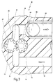
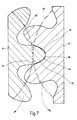
- the contour of the tooth gaps of the one gear is such the teeth of the other gear matched that at full tooth immersed in the tooth gap, the tooth head of which is the tooth gap, radially within the pitch circle, almost completely fills.
- gear pump initially mentioned the helical toothing of the gears is designed such that, along a surface line of Seen gears, at least two tooth head / tooth base supports the meshing gears are present, and that the contour of the Tooth gaps of one gear on the teeth of the other Gear is matched that when completely in the tooth gap immersed tooth whose tooth head is the tooth gap, radially inside of the pitch circle, almost completely filled in such a way that the remaining free spaces are just sufficient to pass on to allow and the leakage cross section only about 1% of the delivery cross section of the tooth gap.
- the two gears are taken up in approximately circular cylindrical, overlapping openings, with a slight radial play.
- the diameter of the cylindrical openings is therefore slight larger than the diameter of the tip circle of the respective gears.
- this area ensures that the transfer of the Conveying fluid of a tooth gap from the suction pressure state to the Discharge pressure is extremely gentle, especially in connection with the helical teeth and the design of the teeth, so that not only an extremely quiet promotion but also a pressure loss-free transition from the tooth gap to Pressure level occurs.
- the combination sickle plus helical teeth leads to a particularly harmonious and gentle, thus also low-noise funding.
- the good seal by the working principle of the invention and less achieved through high precision in parts production also causes a (better than with conventional gear pumps) reproducible correlation between the pressure / flow map, the torque / speed map and the Current / voltage characteristic field. This allows one-off determination of these maps on a series device and the use of these Matrix values for pressure and flow control under waiver to the direct, with a certain effort Outlet pressure measurement.
- a pump body provided, which is releasably connected to a drive body is, in the pump body inlet, cylindrical openings together with gears and the outlet are arranged.
- the pump body designed so that it can be placed on the drive body is.
- This measure has the advantage that handling when disassembling and assembly is particularly simple, i.e. for example after use, only the pump body must be removed from the drive body be taken off, which is very easy and also from untrained persons.
- the pump body connectable to the drive body via a bayonet coupling.
- the pump housing formed as a solid plastic part in which the cylindrical Openings are recessed in such a way that the gears from one side of the pump housing into the cylindrical Openings can be inserted.
- the plastic part can be mass-produced be made so that it can be designed as a disposable part can, i.e. after a single operation, the pump body discarded, and it just gets on the drive body new pump body put on.
- the driven Gear a coupling pin in front of a corresponding Coupling counterpart of a motor in the drive body is insertable.
- This measure has the advantage that the plug-in coupling non-positive connection between the drive and the driven Gear can be made very easily.
- This measure has the advantage that the gear with its drive pin simply by removing the pump cover a bayonet coupling can be removed and replaced.
- the intermediate pin with double joint effect also has its Interchangeability has the advantage that for single and multiple use Pump designs different coupling diameters can be used. This allows for one-time use Execution of the drive pin with the gear to be sprayed as a unit and for reusable designs a rustproof, hardened sufficiently firm Steel spigot with a small outer diameter in the driven Anchor gear. A small pin outer diameter leads to a smaller peripheral speed at the corresponding one Sealing lip and this in turn leads to less wear the seal of the pin.
- the clutch formed between the coupling pin and the motor as a slot coupling.
- This measure has the advantage that a self-aligning Clutch is present, i.e. regardless of the relative rotational position alignment of the coupling pin and coupling counterpart and a shaft offset is compensated for if necessary.
- a is in the outlet Standstill sealing valve arranged.
- This measure has the advantage that when the pump is at a standstill no backflow can occur in either direction.
- the standstill sealing valve designed as a ball check valve.
- This measure has the advantage that, due to a few components, namely through a spring-loaded ball, the outlet against backflow or outflow can be blocked at a standstill, components that can be easily assembled, disassembled and cleaned.
- the standstill sealing valve as a slotted body made of flexible material formed, which is arranged in the cross section of the outlet is.
- Such a passive standstill sealing valve can, for example a simple cross-slotted silicone disc can be formed.
- the outer diameter of the slotted disc corresponds to that Outside diameter of a pump outlet hose.
- the diameter corresponds to the circumferential circle of the cross slots in the disc the inside diameter of the pump outlet hose.
- the washer is simply between the face of the in the pump outlet hose inserted into the housing outlet bore and the inner stop surface of the housing outlet bore held tight.
- the differential pressure for the transition from standstill density on flow can by the slice thickness and / or adjusted by the Shore hardness of the silicone disc become.
- the standstill sealing valve as magnetically powered, with a motor of Plunger connected in parallel, the locking is retractable into the cross section of the outlet when the engine off.
- a flat, not externally interchangeable Tappet belonging to the pump body acts through a Matching slot of the pump housing in the area of the housing outlet bore on a relatively thin-walled one inserted there Silicone tube.
- the housing slot and the anti-rotation plunger cutting edge are designed that regardless of the stroke position of the cutting edge of the pump body attached by bayonet with quarter turn or can be removed.
- the outer diameter of the thin-walled Hose is slightly larger than the diameter of the housing outlet bore. It is inserted using a vacuum finger and is then without gluing during all operating conditions of the housing bore tight.
- a pressure relief valve provided that a pump cover at excess pressure moved relative to the pump housing so that despite running Drive no funding but a return to the inlet takes place.
- a pressure relief valve spring provided with plunger in the drive body, and allows the pump cover to tilt on one side in the event of overpressure away from the pump housing.
- a pressure sensor is added, which has a membrane and a branch line is connected to the outlet.
- the helical toothing is designed as arrow teeth.
- This measure has the advantage that through the arrow teeth a particularly intensive intervention at several points of the combing Gears can be created, and by the arrow arrangement a particularly good seal between the gears is possible and axial forces are compensated.
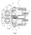
- a gear pump shown in Figures 1 to 10 is in in their entirety with the reference number 10.
- the pump 10 consists of two essential components, namely a pump body 12 and a drive body 14.
- Fig. 1 it is shown that the drive body 14 of the pump 10 is connected to a motor 15.
- the pump body 12 essentially consists of a pump housing 16, one end of this pump cover 54 and gears 42 and 44 accommodated in the pump housing.
- Am Pump housing 16 jump on the drive body 14 facing Side bayonet attachments 18, 18 'and a bayonet stop 21 out.
- the pump body 12 can also have a bayonet coupling the drive body 14 are connected.
- the simple, quick 45 ° bayonet assembly / disassembly of the complete Pump body 12 also allows emergency quick decoupling or switching off the pump 10 in this way, without Spill liquid or the user or the device affect.
- the drive body 14 is in the center Motor shaft 22 added, which on the pump body 12 facing Side is connected to a slot coupling 26.
- the pipe socket 28 or its central continuous cylindrical Bore serves as an inlet 32, which opens into a chamber 34.
- the chamber 34 is in the center, facing the drive body 14 Gap 36 open on the bottom side of the pump body 12 educated.
- the gap opens at the end opposite the inlet 32 36 in an outlet 46, which is a central, continuous bore is formed by the pipe socket 30.
- the gear 42 is provided with an axle pin, which on one End of the gear 42 projects axially and there as a coupling pin 50 is formed.
- One end 52 of the coupling pin 50 is flattened and sharpened.
- the journal and the gear 42 can be made in one or two parts.
- a pump cover 54 which an outer sealing ring 56 opposite the pump housing 16 seals.
- Another seal 58 surrounds the one through the pump cover 54 extending through coupling pin 50 of the gear 42nd
- the coupling pin 50 and thus the gear 42 is sealing, however rotatably guided through the pump cover 54.
- the end 52 engages in a slot coupling 26 of the output shaft 22 of the motor 15 a so that a positive connection is created is.
- the gear 42 is thus the driven gear.
- the other Gear 44 is also free of journal bearings. Both wheels are floated in the cylindrical openings 38 and 40.
- the liquid coming from the inlet 32 is on the radial outside of the Gears 42 and 44 conveyed towards outlet 46.
- a standstill sealing valve 84 is arranged in the outlet 46.
- the standstill sealing valve 84 consists of a force a spring 88 loaded ball 86 by the spring 88 on a valve seat 89 is pressed.
- the force of the spring 88 is set so that the ball 86 operates from the valve seat 89th lifts off so that liquid can be conveyed through the outlet 46 can.
- the ball 86 is countered the valve seat 89 pressed and seals the outlet 46, so that no flow rate flows back or out through the pump 10 can.
- the pump housing 16 can accordingly the sequence from FIG. 10 to FIG. 9 are rotated, which releases the bayonet coupling and the pump housing 16 can be removed from the drive body 14. This solves the coupling pin 50 automatically from the slot coupling 26 of the motor shaft 22 of the motor 15. From the removed pump housing 16 can now 54 after removing the pump cover the gears 42 and 44 removed from the open side and either the individual parts are cleaned and then be sterilized, the simple geometric design of slot 36 and inlet 32 and outlet 46 these measures promote.
- both gears 42 and 44 are provided as plastic gears, thus as one-time disposable parts, so that only the actual pump housing 16th and the lid 54 needs to be cleaned and sterilized.
- the pump housing is also in a further embodiment 16 and the pump cover 54 are designed as disposable parts, so that no sterilization or cleaning operations after use must be carried out.
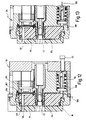
- FIGS. A variant of the pump 10 is shown in FIGS. a pressure relief valve arrangement in the drive body 94 106 is provided.
- a stub 98 leads from the outlet of the Pump housing 16.
- the stub 98 is on a membrane assembly two membranes 100, 102.
- the membrane 102 is part of a pressure sensor 104.
- the pressure sensor 104 thus detects the one present in the outlet Pressure and can therefore detect an overpressure drop.
- the pressure sensor 104 is coupled to the pressure relief valve 106.
- the pressure relief valve 106 has a tappet 108 which over a spring 110 on a diametrically opposite stub 98 Side acts on the lid 96, as in 11 is indicated.
- the pressure limitation can be set via an adjusting screw 112 become.
- the cover 96 is a bit of a tilt edge 114 Bottom of the pump housing away in the direction of the drive body 94 tiltable, as can be seen from the image sequence from FIG. 12 to FIG. 13 is.
- Fig. 12 shows the normal case, i.e. the spring 110 presses over the plunger 108 the cover 96 to the open side of the pump housing 16th
- sealing surfaces 117, 118, 119 and 120 provided that there is sufficient sealing between Show pressure and suction side.
- the remaining area is approximately 0.5 mm hollow and is supplied with outlet pressure.
Landscapes
- Engineering & Computer Science (AREA)
- Mechanical Engineering (AREA)
- General Engineering & Computer Science (AREA)
- Physics & Mathematics (AREA)
- Fluid Mechanics (AREA)
- Rotary Pumps (AREA)
- Details And Applications Of Rotary Liquid Pumps (AREA)
Description
- Fig. 1
- einen Längsschnitt einer medizinischen Zahnradpumpe, die an einem Motor montiert ist,
- Fig. 2
- einen Schnitt längs der Linie II-II in Fig. 1,
- Fig. 3
- eine ausschnittsweise, stark vergrößerte Ansicht des mittigen Bereiches des Schnittes von Fig. 2,
- Fig. 4
- eine Seitenansicht der beiden kämmenden Zahnräder,
- Fig. 5
- eine perspektivische Schrägansicht der beiden kämmenden Zahnräder,
- Fig. 6
- einen Schnitt längs der Linie VI-VI in Fig. 5,
- Fig. 7
- eine stark vergrößerte ausschnittsweise Querschnittdarstellung der beiden kämmenden Zahnräder,
- Fig. 8
- eine Seitenansicht der Pumpe in einem gegenüber der Schnittdarstellung von Fig. 1 um 90° verdrehten Zustand,
- Fig. 9
- eine Draufsicht auf die Pumpe während eines Montageschritts nach Ansetzen eines Pumpenkörpers auf einen Antriebskörper vor Schließen einer Bajonettführung,
- Fig. 10
- eine Draufsicht auf die Pumpe nach Schließen des Bajonettverschlusses, und
- Fig. 11
- eine der Schnittdarstellung von Fig. 2 vergleichbare Darstellung eines weiteren Ausführungsbeispiels mit einer Überdruckventilausgestaltung,
- Fig. 12
- einen der Darstellung von Fig. 1 vergleichbaren ausschnittsweisen Schnitt längs der Linie XII-XII in Fig. 11, wobei im wesentlichen der Schnitt durch den Antriebskörper gezeigt ist, und
- Fig. 13
- eine ausschnittsweise Darstellung des Schnittes von Fig. 12 in einem Überdruckfall.
Claims (16)
- Medizinische Zahnradpumpe zum Saugen und Spülen, insbesondere für die Endoskopie oder das Labor, mit zwei kämmenden Zahnrädern (42, 44) als Förderelemente, von denen eines mit einem Antrieb verbunden ist, und die Zahnräder (42, 44) in zylindrischen Öffnungen (38, 40) eines Pumpengehäuses (16) aufgenommen sind, wobei die Öffnungen (38, 40) mit einem Einlaß (32) und mit einem Auslaß (46) verbunden sind, wobei die Zahnräder (42, 44) zapfenlagerfrei in den Öffnungen (38, 40) aufgenommen sind, und die beiden Zahnräder (42, 44) je mit einer Schrägverzahnung versehen sind, dadurch gekennzeichnet, daß die Schrägverzahnung derart ausgebildet ist, daß, längs einer Mantellinie (67) der Zahnräder (42, 44) gesehen, zumindest zwei Zahnkopf/Zahnfuß-Auflagen (68, 70) der kämmenden Zahnräder (42, 44) vorhanden sind, und daß die Kontur der Zahnlücken (66) des einen Zahnrades (42, 44) derart auf die Zähne (64) des anderen Zahnrades (42, 44) abgestimmt ist, daß bei vollständig in die Zahnlücke (66) eingetauchtem Zahn (64) dessen Zahnkopf (72) die Zahnlücke (66), radial innerhalb des Wälzkreises (76), nahezu vollständig ausfüllt, derart, daß die verbleibenden Freiräume (78, 79) gerade ausreichend sind, um die Abwälzung zu ermöglichen, und der Leckagequerschnitt nur etwa 1 % des Förderquerschnitts der Zahnlücke (66) beträgt.
- Medizinische Zahnradpumpe nach Anspruch 1, dadurch gekennzeichnet, daß ein Pumpenkörper (12) vorgesehen ist, der lösbar mit einem Antriebskörper (14, 94) verbunden ist, wobei im Pumpenkörper (12) Einlaß (32), die zylindrischen Öffnungen (38, 40) samt Zahnrädern (42 und 44) und Auslaß (46) angeordnet sind.
- Medizinische Zahnradpumpe nach Anspruch 2, dadurch gekennzeichnet, daß der Pumpenkörper (12) so ausgebildet ist, daß er auf den Antriebskörper (14, 94) aufsetzbar ist.
- Medizinische Zahnradpumpe nach Anspruch 3, dadurch gekennzeichnet, daß der Pumpenkörper (12) mit dem Antriebskörper (14, 94) über eine Bajonettkupplung (18, 20) verbindbar ist.
- Medizinische Zahnradpumpe nach einem der Ansprüche 2 bis 4, dadurch gekennzeichnet, daß der Pumpenkörper (12) als massives Kunststoffteil ausgebildet ist, in dem die zylindrischen Öffnungen (38, 40) derart ausgespart sind, daß die Zahnräder (42, 44) von einer Seite des Pumpenkörpers (12) her in die zylindrischen Öffnungen (38 und 40) einschiebbar sind.
- Medizinische Zahnradpumpe nach einem der Ansprüche 1 bis 5, dadurch gekennzeichnet, daß von dem angetriebenen Zahnrad (42) ein Kupplungszapfen (50) vorsteht, der in ein entsprechendes Kupplungsgegenstück eines Motores (15) im Antriebskörper (14, 94) einsteckbar ist.
- Medizinische Zahnradpumpe nach Anspruch 6, dadurch gekennzeichnet, daß zwischen dem Kupplungszapfen (50) des angetriebenen Zahnrades (42) und dem Motor (15) ein Zwischenstift angeordnet ist.
- Medizinische Zahnradpumpe nach Anspruch 6 oder 7, dadurch gekennzeichnet, daß die Kupplung zwischen Kupplungszapfen (50) und Motor (15) als Schlitzkupplung (26) ausgebildet ist.
- Medizinische Zahnradpumpe nach einem der Ansprüche 1 bis 8, dadurch gekennzeichnet, daß im Auslaß (46) ein Stillstandsdichtventil (84) angeordnet ist.
- Medizinische Zahnradpumpe nach Anspruch 9, dadurch gekennzeichnet, daß das Stillstandsdichtventil als Kugelrückschlagventil (86, 88) ausgebildet ist.
- Medizinische Zahnradpumpe nach Anspruch 9, dadurch gekennzeichnet, daß das Stillstandsdichtventil als geschlitzter Körper aus flexiblem Material ausgebildet ist, der im Querschnitt des Auslasses (46) angeordnet ist.
- Medizinische Zahnradpumpe nach Anspruch 9, dadurch gekennzeichnet, daß das Stillstandsdichtventil als magnetbetriebener, mit einem Motor des Antriebs parallel geschalteter Stößel ausgebildet ist, der sperrend in den Querschnitt des Auslasses (46) einfahrbar ist, wenn der Motor abschaltet.
- Medizinische Zahnradpumpe nach einem der Ansprüche 2 bis 12, dadurch gekennzeichnet, daß ein Überdruckventil (106) vorgesehen ist, das bei Überdruck einen Deckel (96) relativ zu einem Pumpengehäuse (16) und zum Antriebskörper (14) derart bewegt, daß trotz laufendem Antrieb keine Förderung sondern eine Rückführung zum Einlaß (32) erfolgt.
- Medizinische Zahnradpumpe nach Anspruch 13, dadurch gekennzeichnet, daß eine Überdruckventilfeder (110) mit Stößel (108) im Antriebskörper (94) aufgenommen ist, und daß, im Überdruckfall, der Pumpendeckel (96) seitlich etwas vom Pumpengehäuse (16) einseitig abkippbar ist.
- Medizinische Zahnradpumpe nach Anspruch 13 oder 14, dadurch gekennzeichnet, daß im Antriebskörper (94) ein Drucksensor (104) aufgenommen ist, der über eine Membran (102, 104) und eine Stichleitung (98) mit dem Auslaß in Verbindung steht.
- Medizinische Zahnradpumpe nach einem der Ansprüche 1 bis 15, dadurch gekennzeichnet, daß die Schrägverzahnung der Zahnräder als Pfeilverzahnung ausgebildet ist.
Applications Claiming Priority (3)
| Application Number | Priority Date | Filing Date | Title |
|---|---|---|---|
| DE19725462A DE19725462A1 (de) | 1997-06-16 | 1997-06-16 | Medizinische Zahnradpumpe zum Saugen und Spülen |
| DE19725462 | 1997-06-16 | ||
| PCT/EP1998/003601 WO1998058174A1 (de) | 1997-06-16 | 1998-06-15 | Medizinische zahnradpumpe zum saugen und spülen |
Publications (2)
| Publication Number | Publication Date |
|---|---|
| EP0920588A1 EP0920588A1 (de) | 1999-06-09 |
| EP0920588B1 true EP0920588B1 (de) | 2003-06-11 |
Family
ID=7832654
Family Applications (1)
| Application Number | Title | Priority Date | Filing Date |
|---|---|---|---|
| EP98939503A Expired - Lifetime EP0920588B1 (de) | 1997-06-16 | 1998-06-15 | Medizinische zahnradpumpe zum saugen und spülen |
Country Status (4)
| Country | Link |
|---|---|
| US (1) | US6361289B1 (de) |
| EP (1) | EP0920588B1 (de) |
| DE (2) | DE19725462A1 (de) |
| WO (1) | WO1998058174A1 (de) |
Families Citing this family (19)
| Publication number | Priority date | Publication date | Assignee | Title |
|---|---|---|---|---|
| DE19725462A1 (de) | 1997-06-16 | 1998-12-24 | Storz Endoskop Gmbh | Medizinische Zahnradpumpe zum Saugen und Spülen |
| JPH11247767A (ja) | 1997-12-23 | 1999-09-14 | Maag Pump Syst Textron Ag | 歯車ポンプの軸を位置決めするための方法および歯車ポンプ |
| US7001378B2 (en) * | 1998-03-31 | 2006-02-21 | Innercool Therapies, Inc. | Method and device for performing cooling or cryo-therapies, for, e.g., angioplasty with reduced restenosis or pulmonary vein cell necrosis to inhibit atrial fibrillation employing tissue protection |
| DE19962498A1 (de) | 1999-12-23 | 2001-07-05 | Storz Endoskop Gmbh Schaffhaus | Pumpenkörper für eine medizinische Zahnradpumpe |
| US6632145B2 (en) * | 2000-02-14 | 2003-10-14 | Arthur Vanmoor | Fluid displacement pump with backpressure stop |
| US6588207B1 (en) * | 2001-03-29 | 2003-07-08 | Alphonse A. Pouliot | Step-less, hydraulic power transmission |
| FR2859000B1 (fr) * | 2003-08-20 | 2005-09-30 | Renault Sa | Dent d'engrenage et pompe a engrenages exterieurs |
| DE102004063647A1 (de) * | 2004-12-31 | 2006-07-20 | Tecpharma Licensing Ag | Vorrichtung zur dosierten Verabreichung eines fluiden Produkts mit Kupplung |
| US8011910B2 (en) * | 2005-02-22 | 2011-09-06 | Limo-Reid, Inc. | Low noise gear set for gear pump |
| EP2016287B1 (de) * | 2006-05-10 | 2018-07-11 | Robert Bosch GmbH | Drehkolbenmaschine |
| DE102007033659A1 (de) * | 2007-07-17 | 2009-01-22 | Cor Pumps + Compressors Ag | Stirnzahnradumwälzpumpe |
| DE102008028059B4 (de) | 2008-06-12 | 2016-12-01 | Wmf Württembergische Metallwarenfabrik Ag | Verdrängerpumpe |
| US8900878B2 (en) | 2008-11-28 | 2014-12-02 | Roche Molecular Systems Inc. | Pipetting device, modular pipetting unit, pipetting system and method for pipetting of fluid samples |
| DE102009051443A1 (de) | 2009-10-30 | 2011-05-05 | Storz Endoskop Produktions Gmbh | Medizinische Zahnradpumpe |
| RU2553848C1 (ru) * | 2014-05-28 | 2015-06-20 | Виктор Владимирович Становской | Шестеренная машина |
| EP3368770A1 (de) * | 2015-10-30 | 2018-09-05 | GE Healthcare Bio-Sciences AB | Verbesserungen an und im zusammenhang mit zahnradpumpen |
| DE102017003783A1 (de) * | 2017-04-20 | 2018-10-25 | Wabco Gmbh | Vorrichtung zum Verbinden eines Druckluftkompressors mit einem Antriebsmotor sowie Druckluftkompressor |
| RU182027U1 (ru) * | 2018-02-06 | 2018-07-31 | федеральное государственное автономное образовательное учреждение высшего образования "Самарский национальный исследовательский университет имени академика С.П. Королева" | Шестеренный насос |
| CN109621031A (zh) * | 2018-12-29 | 2019-04-16 | 东莞康智医疗器械有限公司 | 一种便携式负压引流装置 |
Family Cites Families (20)
| Publication number | Priority date | Publication date | Assignee | Title |
|---|---|---|---|---|
| US2462924A (en) | 1944-03-01 | 1949-03-01 | Equi Flow Inc | Gear tooth profile |
| DE1822807U (de) * | 1959-01-15 | 1960-12-01 | Kirk & Kompagni | Zahnradpumpe fuer homogenisatoren. |
| DE1821554U (de) * | 1960-07-07 | 1960-11-10 | Harry Thalheim | Von einem motor angetriebene zahnradpumpe fuer kleine leistungen. |
| DE1975041U (de) * | 1967-08-02 | 1967-12-14 | Richter K G J | Zahnradpumpe. |
| US3870437A (en) * | 1972-06-29 | 1975-03-11 | John T Gondek | Planetary gear pump |
| US3890068A (en) * | 1973-06-28 | 1975-06-17 | Borg Warner | Sealing arrangement for a fluid pressure device |
| CH613258A5 (de) * | 1975-09-24 | 1979-09-14 | Suter Fa Alois | |
| US4065235A (en) * | 1976-06-01 | 1977-12-27 | Tuthill Pump Company | Gear pump |
| SE415054B (sv) * | 1978-09-06 | 1980-09-01 | Bonnierfoeretagen Ab | Kugghjulsmaskin |
| AU8288382A (en) * | 1981-05-13 | 1982-11-18 | Smeg Elettrodomestici S.P.A. | Dishwashing machine tank well |
| DE8331598U1 (de) * | 1983-11-04 | 1985-04-11 | Barmag Barmer Maschinenfabrik Ag, 5630 Remscheid | Zahnradpumpe zur volumetrischen mengendosierung mit einer verbesserten spuelung |
| DE3340748C2 (de) * | 1983-11-10 | 1986-09-25 | Fresenius AG, 6380 Bad Homburg | Zahnradpumpe, insbesondere für medizinische Zwecke |
| DE3943369A1 (de) * | 1989-12-30 | 1991-07-11 | Fresenius Ag | Zahnradpumpe, insbesondere gekapselte medizinische zahnradpumpe |
| US5163824A (en) | 1990-04-23 | 1992-11-17 | Transcience Associates Inc. | Rubber-geared pump with shaftless gear |
| US5108275A (en) * | 1990-12-17 | 1992-04-28 | Sager William F | Rotary pump having helical gear teeth with a small angle of wrap |
| EP0692266B1 (de) * | 1991-08-21 | 2000-03-22 | Smith & Nephew, Inc. | Flüssigkeitsbehandlungssystem |
| KR100243893B1 (ko) * | 1993-09-30 | 2000-03-02 | 다나까 도미오 | 기어펌프 |
| WO1996001950A1 (en) | 1994-07-07 | 1996-01-25 | David Brown Hydraulics Limited | Helical gear pump or motor |
| JP4057059B2 (ja) * | 1995-12-11 | 2008-03-05 | アトリエ ブッシュ ソシエテ アノニム | コンベアウォーム |
| DE19725462A1 (de) | 1997-06-16 | 1998-12-24 | Storz Endoskop Gmbh | Medizinische Zahnradpumpe zum Saugen und Spülen |
-
1997
- 1997-06-16 DE DE19725462A patent/DE19725462A1/de not_active Withdrawn
-
1998
- 1998-06-15 EP EP98939503A patent/EP0920588B1/de not_active Expired - Lifetime
- 1998-06-15 DE DE59808687T patent/DE59808687D1/de not_active Expired - Lifetime
- 1998-06-15 WO PCT/EP1998/003601 patent/WO1998058174A1/de not_active Ceased
- 1998-06-15 US US09/242,392 patent/US6361289B1/en not_active Expired - Fee Related
Also Published As
| Publication number | Publication date |
|---|---|
| US6361289B1 (en) | 2002-03-26 |
| EP0920588A1 (de) | 1999-06-09 |
| DE59808687D1 (de) | 2003-07-17 |
| WO1998058174A1 (de) | 1998-12-23 |
| DE19725462A1 (de) | 1998-12-24 |
Similar Documents
| Publication | Publication Date | Title |
|---|---|---|
| EP0920588A1 (de) | Medizinische zahnradpumpe zum saugen und spülen | |
| EP3050585B1 (de) | Dosiergerät zur Abgabe eines Fluids unter aseptischen Bedingungen | |
| DE69006239T2 (de) | Kassette für eine peristaltische Pumpe mit quetschbarem Schlauch und peristaltische Pumpe mit einer solchen Kassette. | |
| DE69725311T2 (de) | Injektionssystem und darin zur anwendung kommendes pumpsystem | |
| EP2663771B1 (de) | Kolbenpumpe | |
| EP2627905B1 (de) | Pumpenmodul, pumpenbasismodul und pumpensystem | |
| DE69616336T2 (de) | Peristaltikpumpe | |
| DE60221239T2 (de) | Hochdruckeinwegpumpenkassette zur anwendung auf medizinischem gebiet | |
| DE19847132C2 (de) | Außenzahnradpumpe mit Fördervolumenbegrenzung | |
| EP3515519B1 (de) | Vorrichtung zum absaugen von körperfluiden und zum zuführen einer substanz | |
| EP3515518A2 (de) | Absaug- und zuführvorrichtung mit antriebseinheit und anschlussteil | |
| DE3044363C2 (de) | ||
| WO2018215542A1 (de) | Steriles pumpmodul für eine infusionspumpe | |
| EP1155240B1 (de) | Medizinische Zahnradpumpe | |
| EP0085702A1 (de) | Hermetisch gekapselte zentrifugalpumpe zur schonenden förderung von fluiden | |
| DE2634318A1 (de) | Pumpe, vorzugsweise zum dosieren und kalibrieren | |
| DE1553043A1 (de) | Rotationspumpe | |
| DE102004021216A1 (de) | Hochdruck-Innenzahnradmaschine mit mehrfacher hydrostatischer Lagerung pro Hohlrad | |
| DE102009051443A1 (de) | Medizinische Zahnradpumpe | |
| DE1911919B2 (de) | Membranpumpe zum dosieren von fluessigkeiten | |
| EP3600470A1 (de) | Vorrichtung mit einer koppelbaren peristaltikpumpeneinheit | |
| DE2240231A1 (de) | Pulsierende herzpumpe | |
| DE102023124478A1 (de) | Kolbenpumpe für eine Vorrichtung zur extrakorporalen Blutbehandlung | |
| EP3237758A1 (de) | Fördervorrichtung | |
| DE102006013983B4 (de) | Herzunterstützungssystem oder künstliches Herz |
Legal Events
| Date | Code | Title | Description |
|---|---|---|---|
| PUAI | Public reference made under article 153(3) epc to a published international application that has entered the european phase |
Free format text: ORIGINAL CODE: 0009012 |
|
| 17P | Request for examination filed |
Effective date: 19990312 |
|
| AK | Designated contracting states |
Kind code of ref document: A1 Designated state(s): DE FR GB IT |
|
| 17Q | First examination report despatched |
Effective date: 20020225 |
|
| GRAH | Despatch of communication of intention to grant a patent |
Free format text: ORIGINAL CODE: EPIDOS IGRA |
|
| GRAH | Despatch of communication of intention to grant a patent |
Free format text: ORIGINAL CODE: EPIDOS IGRA |
|
| GRAA | (expected) grant |
Free format text: ORIGINAL CODE: 0009210 |
|
| AK | Designated contracting states |
Designated state(s): DE FR GB IT |
|
| PG25 | Lapsed in a contracting state [announced via postgrant information from national office to epo] |
Ref country code: GB Free format text: LAPSE BECAUSE OF FAILURE TO SUBMIT A TRANSLATION OF THE DESCRIPTION OR TO PAY THE FEE WITHIN THE PRESCRIBED TIME-LIMIT Effective date: 20030611 |
|
| REG | Reference to a national code |
Ref country code: GB Ref legal event code: FG4D Free format text: NOT ENGLISH |
|
| REF | Corresponds to: |
Ref document number: 59808687 Country of ref document: DE Date of ref document: 20030717 Kind code of ref document: P |
|
| PLBE | No opposition filed within time limit |
Free format text: ORIGINAL CODE: 0009261 |
|
| STAA | Information on the status of an ep patent application or granted ep patent |
Free format text: STATUS: NO OPPOSITION FILED WITHIN TIME LIMIT |
|
| ET | Fr: translation filed | ||
| GBT | Gb: translation of ep patent filed (gb section 77(6)(a)/1977) |
Effective date: 20040421 |
|
| 26N | No opposition filed |
Effective date: 20040312 |
|
| PGFP | Annual fee paid to national office [announced via postgrant information from national office to epo] |
Ref country code: GB Payment date: 20110606 Year of fee payment: 14 |
|
| PGFP | Annual fee paid to national office [announced via postgrant information from national office to epo] |
Ref country code: IT Payment date: 20110527 Year of fee payment: 14 |
|
| PGFP | Annual fee paid to national office [announced via postgrant information from national office to epo] |
Ref country code: FR Payment date: 20110727 Year of fee payment: 14 |
|
| GBPC | Gb: european patent ceased through non-payment of renewal fee |
Effective date: 20120615 |
|
| PG25 | Lapsed in a contracting state [announced via postgrant information from national office to epo] |
Ref country code: IT Free format text: LAPSE BECAUSE OF NON-PAYMENT OF DUE FEES Effective date: 20120615 |
|
| REG | Reference to a national code |
Ref country code: FR Ref legal event code: ST Effective date: 20130228 |
|
| PG25 | Lapsed in a contracting state [announced via postgrant information from national office to epo] |
Ref country code: GB Free format text: LAPSE BECAUSE OF FAILURE TO SUBMIT A TRANSLATION OF THE DESCRIPTION OR TO PAY THE FEE WITHIN THE PRESCRIBED TIME-LIMIT Effective date: 20120615 Ref country code: FR Free format text: LAPSE BECAUSE OF NON-PAYMENT OF DUE FEES Effective date: 20120702 |
|
| PGFP | Annual fee paid to national office [announced via postgrant information from national office to epo] |
Ref country code: DE Payment date: 20140523 Year of fee payment: 17 |
|
| REG | Reference to a national code |
Ref country code: DE Ref legal event code: R119 Ref document number: 59808687 Country of ref document: DE |
|
| PG25 | Lapsed in a contracting state [announced via postgrant information from national office to epo] |
Ref country code: DE Free format text: LAPSE BECAUSE OF NON-PAYMENT OF DUE FEES Effective date: 20160101 |