EP0920156A2 - Dispositif pour transmettre des états de connection, dispositif pour générer des données associées d'affichage et procédé pour afficher celles-ci - Google Patents
Dispositif pour transmettre des états de connection, dispositif pour générer des données associées d'affichage et procédé pour afficher celles-ci Download PDFInfo
- Publication number
- EP0920156A2 EP0920156A2 EP98122156A EP98122156A EP0920156A2 EP 0920156 A2 EP0920156 A2 EP 0920156A2 EP 98122156 A EP98122156 A EP 98122156A EP 98122156 A EP98122156 A EP 98122156A EP 0920156 A2 EP0920156 A2 EP 0920156A2
- Authority
- EP
- European Patent Office
- Prior art keywords
- node
- data
- display data
- connecting status
- connection display
- Prior art date
- Legal status (The legal status is an assumption and is not a legal conclusion. Google has not performed a legal analysis and makes no representation as to the accuracy of the status listed.)
- Withdrawn
Links
Images


Classifications
-
- H—ELECTRICITY
- H04—ELECTRIC COMMUNICATION TECHNIQUE
- H04L—TRANSMISSION OF DIGITAL INFORMATION, e.g. TELEGRAPHIC COMMUNICATION
- H04L12/00—Data switching networks
- H04L12/28—Data switching networks characterised by path configuration, e.g. LAN [Local Area Networks] or WAN [Wide Area Networks]
- H04L12/40—Bus networks
- H04L12/40052—High-speed IEEE 1394 serial bus
- H04L12/40117—Interconnection of audio or video/imaging devices
-
- H—ELECTRICITY
- H04—ELECTRIC COMMUNICATION TECHNIQUE
- H04L—TRANSMISSION OF DIGITAL INFORMATION, e.g. TELEGRAPHIC COMMUNICATION
- H04L12/00—Data switching networks
- H04L12/28—Data switching networks characterised by path configuration, e.g. LAN [Local Area Networks] or WAN [Wide Area Networks]
- H04L12/40—Bus networks
- H04L12/40006—Architecture of a communication node
- H04L12/40013—Details regarding a bus controller
-
- H—ELECTRICITY
- H04—ELECTRIC COMMUNICATION TECHNIQUE
- H04L—TRANSMISSION OF DIGITAL INFORMATION, e.g. TELEGRAPHIC COMMUNICATION
- H04L12/00—Data switching networks
- H04L12/28—Data switching networks characterised by path configuration, e.g. LAN [Local Area Networks] or WAN [Wide Area Networks]
- H04L12/40—Bus networks
- H04L12/40006—Architecture of a communication node
- H04L12/40019—Details regarding a bus master
-
- H—ELECTRICITY
- H04—ELECTRIC COMMUNICATION TECHNIQUE
- H04L—TRANSMISSION OF DIGITAL INFORMATION, e.g. TELEGRAPHIC COMMUNICATION
- H04L12/00—Data switching networks
- H04L12/28—Data switching networks characterised by path configuration, e.g. LAN [Local Area Networks] or WAN [Wide Area Networks]
- H04L12/40—Bus networks
- H04L12/40052—High-speed IEEE 1394 serial bus
- H04L12/40071—Packet processing; Packet format
-
- H—ELECTRICITY
- H04—ELECTRIC COMMUNICATION TECHNIQUE
- H04L—TRANSMISSION OF DIGITAL INFORMATION, e.g. TELEGRAPHIC COMMUNICATION
- H04L12/00—Data switching networks
- H04L12/28—Data switching networks characterised by path configuration, e.g. LAN [Local Area Networks] or WAN [Wide Area Networks]
- H04L12/40—Bus networks
- H04L12/40052—High-speed IEEE 1394 serial bus
- H04L12/40078—Bus configuration
-
- H—ELECTRICITY
- H04—ELECTRIC COMMUNICATION TECHNIQUE
- H04L—TRANSMISSION OF DIGITAL INFORMATION, e.g. TELEGRAPHIC COMMUNICATION
- H04L12/00—Data switching networks
- H04L12/28—Data switching networks characterised by path configuration, e.g. LAN [Local Area Networks] or WAN [Wide Area Networks]
- H04L12/44—Star or tree networks
-
- H—ELECTRICITY
- H04—ELECTRIC COMMUNICATION TECHNIQUE
- H04L—TRANSMISSION OF DIGITAL INFORMATION, e.g. TELEGRAPHIC COMMUNICATION
- H04L45/00—Routing or path finding of packets in data switching networks
- H04L45/02—Topology update or discovery
Definitions
- the present invention relates to an apparatus for transmitting connecting status, an apparatus for generating display data thereof and a method of displaying the same suitable for networks corresponding to the IEEE 1394 standard.
- IEEE 1394 The Institute of Electrical and Electronics Engineers, Inc. 1394 has prevailed as a unified standard for digital interface systems and as a low-cost peripheral interface suitable for multimedia use in order to transmit and receive data among digital image devices. IEEE 1394 enables multiplex transfer of a plurality of channels. IEEE 1394 has also become a digital interface suitable for image transmission because it has an isochronous transferring function which assures the transfer of image and voice data in a given period of time.
- IEEE 1394 can form topologies in daisy-chain and tree shapes, and each bus is able to be connected with up to 63 nodes.
- Present connecting status is designed to be managed by a bus manager provided in a predetermined single node in a bus.
- data transfer protocol of IEEE 1394 is defined by three layers (hereinafter also defined as 1394 layers), a physical layer, a link layer and a transaction layer.
- 1394 layers have been standardized, there is no common standard for display layers which regulate management of hardware and provision of user interface at a node using operating system (hereinafter referred to as OS).
- OS operating system
- API Application Programming Interface
- API cannot be made common because standardization of data formats for connecting information from a bus manager has not been realized yet.
- a maximum number of hierarchies (hop count) from a root is limited to 16 when connection is done in a tree-shape.
- hop count When connecting status is not displayed in an easy way to secure the hop count, users might connect exceeding a maximum hop count permitted. Besides, when connection exceeded a maximum hop count, it is not simple to distinguish equipment which should be disconnected.
- An apparatus for transmitting connecting status comprises a computing means for computing correspondence of ID of each node to that of its parent node on the basis of data showing port status in a topology map of a network and generating parent node ID information; and a data outputting means for generating connection display data in a predetermined data format out of the parent node ID information and transmitting the data, or generating transmission data in a predetermined transmission data format out of the connection display data and transmitting the data onto the network.
- An apparatus for generating connecting status display data comprises an image data generating means where connection display data in a predetermined data format, which are generated on the basis of parent node ID information to show correspondence of ID of each node to that of its parent node in a network, or transmission data in a predetermined transmission data format, which are generated on the basis of the connection display data, are inputted and image data are generated in order to display connecting status of the network on the basis of the inputted connection display data or of connection display data fetched from the transmission data.
- a method of displaying connecting status comprises a procedure to compute correspondence of ID of each node to that of its parent node on the basis of data, which show status of ports in a topology map of a network, and to generate parent node ID information, a procedure to generate and transmit connection display data in a predetermined data format out of the parent node ID information or to generate transmission data in a predetermined transmission data format out of the connection display data and to transmit the data onto the networks and a procedure to have the connection display data or the transmission data transmitted through a predetermined transmission path inputted and to generate image data for displaying connection status of the network on the basis of the inputted connection display data or connection display data fetched from the transmission data.
- Figs. 1 and 2 are block diagrams to show embodiments, respectively, of an apparatus for transmitting connecting status and of an apparatus for generating connecting status display data according the present invention.
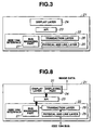
- Fig. 3 is a block diagram showing a protocol configuration of IEEE 1394.
- a protocol configuration of a node 21 includes the IEEE 1394 interface 22, the API 23 and the display layer 24.
- the IEEE 1394 interface 22 has a bus managing part 27 as well as three of 1394 layers, a physical and link layer 25 and a transaction layer 26.
- the physical and link layer 25 is an interface of a physical layer and a link layer, and performs, at the physical layer, encoding and decoding processes of transmission data, bus arbitration process and interfacing process with medium, and at the link layer, transmitting/receiving of packets and cycle control.
- the transaction layer 26 regulates transmission of commands and protocol of receiving, and transmits/receives transmission data to/from transmission media (IEEE 1394 bus), which are not shown, through the physical and link layer 25.
- IEEE 1394 bus IEEE 1394 bus
- the transaction layer 26 transmits data, commands or functions together with the display layer 24 through the API 23.
- the API 23 is an interface for applications to use services such as OS, and the display layer 24 manages hardware and provides user-interface. For example, when the display layer 24 has a displaying part, displaying on the basis of the connection display data inputted through the API 23 becomes possible if connection display data are standardized.
- a bus managing part 27 is provided at the IEEE 1394 interface 22.
- the bus managing part 27 is for performing node control and bus management, such as control of cycle master, control to optimize functions, power supply management, transmission speed management and configuration management. Control of nodes enables communication between nodes.
- each node is connected in daisy-chain or tree shape.
- bus reset takes place and information about connecting status of nodes (connecting information) is initialized.
- each node has information about whether it is in a branch connected with a plurality of other nodes or in a leaf connected with only 1 node or in non-terminating status.
- topology is distinguished first. That is, after bus reset, all leaf nodes send parent-notify signals, a notice from a child node to a parent node, through a port where the branch node is connected (hereinafter referred to as parent port).
- parent port A branch node which receives the parent-notify signal sends child-notify signals, a notice from a parent node to a child node, through a port where the signal was received (hereinafter referred to as child port).
- parentage is determined between two nodes.
- a branch node with a port which has received neither parent-notify signals nor child-notify signals, sends parent-notify signals through this port.
- the one which received a parent-notify signal earlier becomes a parent node, and the other becomes a child node.
- a parent node determined last in a bus becomes a root. After topology is distinguished, node ID is distinguished.
- each node is given a node ID with a lower ID number, when it is connected with a port with a lower port number among nodes in each layer. And, a node ID with a lower number is added to a node which is connected with a lower side of hierarchy. Consequently, connection is done to a port with a lowest number among nodes in each layer, including root, and a node ID of a leaf node, which is positioned in the lowest layer from the root, becomes 0.
- this branch node becomes node ID 1
- a node ID of a leaf node which is connected with the second lowest port number and positioned in the lowest layer, becomes 1.
- a node whose node ID is 0, first broadcasts that its self node ID is 0 to other nodes. Then, other nodes make the number of self node ID packets received from other nodes at the broadcast time their self node ID. In the order described above, each node broadcasts its self node ID until all nodes broadcast their self node IDs.
- Self node IDs from each node are transmitted by self ID packets.
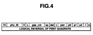
- Fig. 4 illustrates a configuration of a self ID packet.
- a self ID packet in a self ID packet, "10" is arranged at the head, followed by phy_ID,”0", “L”, gap_cnt, sp, del, c, pwr, p0, p1.
- p2, i, m showing self node IDs, then, in the next 32 bits, logical reversal signals of a first quadrate are arranged.
- p0, p1, p2 respectively show three port statuses in 2 bits each
- 11" shows that it is connected with child nodes
- 10 shows that it is connected with a parent node
- 01" shows no connection with other nodes
- "00" shows no ports.
- p3, p4, ... are supposed to be transmitted in the next quadrate to show port status.
- the bus managing part 27 has a bus manager which is not shown.
- the bus manager is supposed to be given self ID packets transmitted from all nodes and to generate a topology map, a set of first quadrates of all self ID packets.
- a connecting information read circuit 2 is designed to read information of a topology map 1 generated by a bus manager in the bus managing part 27.
- the connecting information read circuit 2 outputs information, which it reads, to a parent node ID LIST generating circuit 3.
- Figs. 5 and 6 illustrate the parent node ID list generating circuit 3.
- Fig. 5 shows the state of a bus with six nodes, to which nodes #0 to #5 are connected. And, in the example in Fig. 5, port numbers are expressed with figures next to a code (p). Each node #0 to #5 is respectively allotted #0 to #5 as its node ID through the distinguishing method of node ID. A node whose node ID is 5 is a root.
- the parent node ID list generating circuit 3 is designed to compute ID of a parent node against each child node to enable to secure connecting status.
- the parent node ID list generating circuit 3 examines IDs of child nodes of each node first, then, computes a parent node of each node on the basis of the result.
- the parent node ID list generating circuit 3 first examines, about all nodes on a network, the data to show port status, p0, p1 and p2, to count the number of child ports where child nodes are connected (hereinafter referred to as child number).
- the parent node ID list generating circuit 3 examines nodes having child ports, that is, nodes having child nodes, starting with one having the lowest node number, to compute node ID of child nodes.
- ID of a child node is a number obtained by subtracting 1 from ID of the parent node.
- the parent node ID list generating circuit 3 examines the next node #3 whether it has any child ports.
- Node #3 as shown in Table 1, has 2 child ports. Consequently, for node #3, at least one child node is node #2 whose node ID is smaller than 3 by 1.
- the other child node for node #3 is a node, whose node ID is lower than that of node #2, and one which has not become a child node of other node.
- node #1 is a child node of node #2
- the other child node for node #3 is node #0 whose node ID is 0.
- the parent node ID list generating circuit 3 examines node IDs of child nodes of each node in order of lower node number.
- child number of node #4 and node #5 are both 1. Consequently, node ID of child node of these nodes are 3 and 4 respectively.
- the parent node ID list generating circuit 3 computes node IDs of child nodes of each node.
- the parent node ID list generating circuit 3 using the fact that any node, except a root, is connected with 1 parent node, seeks for the relation of node ID of each node to that of its parent node by tracing back information about child nodes connected to each node. Table 2 below shows the relations between each node and its parent node. Node ID 0 1 2 3 4 Node ID of parent 3 2 3 4 5
- Fig. 6 shows a state of a bus with eight nodes, to which nodes #0 to #8 are connected.
- each of nodes #0 to #7 is allotted #0 to #7 as its node ID respectively by the node ID distinguishing method.
- a node allotted node ID 7 is a root.
- the parent node ID list generating circuit 3 is supposed to examine first ID of child nodes of each node, then, to compute a parent node of each node. That is, the parent node ID list generating circuit 3 examines, on all nodes on a network, p0, p1 and p2, data showing post status, to count child numbers.
- Table 3 below provides information to show child number of each node counted by the parent node ID list generating circuit 3. Node ID 0 1 2 3 4 5 6 7 Child number 0 0 1 0 3 0 1 2
- the parent node ID list generating circuit 3 examines nodes having child ports in order of the lowest node number to compute node IDs of child nodes.
- there is no child port for nodes #0 and #1. Since child number of the next node #2 is 1, a child node for this node is node #1 whose node ID is 1 ( 2 - 1).
- next node #3 has no child port, and the following node #4 has 3 child ports as shown in Table 3.
- node #4 at least 1 child node is node #3 whose node ID is 2, smaller than 3 by 1. Remaining 2 child nodes of node #3 are found, from Table 3, to be node #2 and node #0 which are nodes with node IDs lower than node #4 and have not become a child node of other nodes.
- the parent node ID list generating circuit 3 examines node ID of child nodes of each node in order of the lowest node number.
- child node of node #6 is node #5
- child nodes of node #7 are node #6 and node #4.
- the parent node ID list generating circuit 3 seeks for relations of node ID of each node to that of its parent node on the basis of computed node IDs of child nodes of each node.
- Table 4 shows relations of each node to its parent node in the case of Fig. 6. Node ID 0 1 2 3 4 5 6 Node ID of parent 4 2 4 4 7 6 7
- the parent node ID list generating circuit 3 is designed to output generated information about ID relations between a node and its parent node to a connection display data generating circuit 4.
- connection display data generating circuit 4 generates connection display data in a predetermined data format out of inputted information, and outputs the data to a formatting 5.
- the formatting 5 is designed to convert the inputted connection display data into a transmission data format before outputting them.
- Fig. 7A illustrates a connection display data format
- Fig. 7B illustrates a transmission data format
- connection display data generating circuit 4 shows a node ID in 8 bits, and at the same time, it shows ID of its parent node in 8 bits so as to generate connection display data by grouping data of each node with its parent's.
- Figures in parentheses in Fig. 7A express node IDs in the example in Fig. 5.
- Fig. 7B shows a configuration of an asynchronous packet of IEEE 1394.
- An asynchronous packet is formed by arranging a header, a header CRC, data and data CRC.
- the formatting 5 arranges connection display data at the part for data of an asynchronous packet of IEEE 1394.
- the formatting 5 is designed to arrange connection display data in an asynchronous packet before transmitting them.
- Transmission data from the formatting 5 is transmitted to an IEEE 1394 bus through a terminal 6 which is not shown.
- Connection display data from the connection display data generating circuit 4 is also designed to be able to be outputted as they are through a terminal 7.
- transmission data transmitted through an IEEE 1394 bus are supplied to a transmission data decoding circuit 11 through a terminal 9.
- the transmission data decoding circuit 11 is designed to depacket an inputted asynchronous packet and to supply connection display data arranged at the part for data to a connecting status image data generating circuit 12.
- connection display data may be inputted to a terminal 10.
- connection display data from the terminal 10 are directly supplied to the connecting status image data generating circuit 12.
- the connecting status image data generating circuit 12 is designed to generate, from inputted connection display data, image data to show connecting status of a network and to supply the data to a displaying circuit 13.
- the connecting status image data generating circuit 12 when the connection display data shown in Fig. 7A are inputted, generates connecting status image data shown in Fig. 5. That is, since the connection display data have node IDs and the IDs of their parent nodes arranged in order of lower node ID, the connecting status image data generating circuit 12 generates a display of boxes indicating nodes in their arranged order (in order of lower node ID) and a display indicating boxes of their parent nodes, connects them with lines. Thus, it sequentially arranges boxes correspondingly to connection display data, connects them with lines so as to generate image data for a display to show connecting status.
- Device information is composed of a device name of each device, icons to express devices (graphic information) and so on.
- Configuration ROM is a memory space in each device stipulated by IEEE 1212 as well as being a memory space readable for other devices. For device information, information read from this memory space may be used.
- the connecting status image data generating circuit 12 when device information is inputted from the terminal 8, is designed to generate image data to display information supplied by device information so as to display device names and icons of devices, instead of box displays and so on to show nodes.
- the displaying circuit 13 is designed to display images based on image data from the connecting status image data generating circuit 12.
- the formatting 5 and the transmission data decoding circuit 11 can be realized by the physical and link layer 25 and the transaction layer 26.
- Figs. 8 through 10 illustrate flows of connection display data and transmission data shown by the arrow.
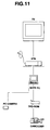
- Figs. 11 and 12 illustrate examples of image display by the displaying circuit 13.
- Figs. 11 and 12 show display examples corresponding to the topology of Figs. 5 and 6 respectively.
- Figs. 1 and 2 that the topology map 1, the connecting information read circuit 2, the parent node ID list generating circuit 3, the connection display data generating circuit 4, the connecting status image data generating circuit 12 and the displaying circuit 13 are provided on devices of a same node.
- Fig. 8 shows an example of this case.
- the bus managing part 27 is supposed to have its functions provided by software.
- the connecting information read circuit 2, the parent node ID list generating circuit 3 and the connection display data generating circuit 4 in Fig. 1 are supposed to be composed by the bus managing part 27.
- Anode 21 receives self ID packets from each node through an IEEE 1394 bus.
- the self ID packets are supplied to the bus managing part 27 through the physical and link layer 25 and the transaction layer 26.
- the bus managing part 27 configures a topology map 1 from self ID packets.
- the connecting information read circuit 2 composed by the bus managing part 27 reads information of the topology map 1, and gives it to the parent node ID list generating circuit 3.
- the parent node ID list generating circuit 3 generates a parent node ID list about every node to indicate which node is its parent node.
- the connection display data generating circuit 4 generates connection display data on the basis of the parent node ID list, and outputs the data from the terminal 7.
- Connection display data are supplied from the bus managing part 27 to the display layer 24 through the API 23.
- the display layer 24 has a displaying part 31 which is supposed to have functions of the connecting status image data generating circuit 12 shown in Fig. 2.
- Connection display data inputted through the terminal 10 are supplied to the connecting status image data generating circuit 12.
- the connecting status image data generating circuit 12 generates image data to show a display of connecting status of a network out of correspondence of each node to its parent node given by connection display data.
- connection display data corresponds to Table 2 above.
- the connecting status image data generating circuit 12 first generates a display of a box to express that node ID is 0, next, on the upper side of this box, a box to express node #3, a parent node, and connects them with lines from a position of the box expressing node #0, where to correspond to the parent port, to a position of the box expressing node #3, where to correspond to the child port.
- the connecting status image data generating circuit 12 generates a display of a box to express that node ID is 1 on the basis of its connection display data , and on the upper side of this box, a box to express node #2, a parent node, and connects them with lines from a position of the box expressing node #1, where to correspond to the parent port, to a position of the box expressing node #2, where to correspond to the child port. Since the box expressing node #3, the parent node of node #2, has already been generated, the connecting status image data generating circuit 12 next connects with lines from a position of the box expressing node #2, where to correspond to the parent port, to a position of the box expressing node #3, where to correspond to the child port.
- device information is transmitted from each node through an IEEE 1394 bus.
- This device information is supplied to the displaying part 31 of the display layer 24 through the physical and link layer 25, the transaction layer 26, and the API 23 to be supplied to the connecting status image data generating circuit 12 which composes the displaying part 31.
- the connecting status image data generating circuit 12 using the inputted device information, generates image data to display names and icons of devices instead of boxes to express each node and the names of the nodes in Fig. 5.
- Fig. 11 shows a display on a displaying screen of the displaying circuit 13 in this case.
- the example in Fig. 11 expresses that nodes #0 to #5 are a PC camera, a camcorder, a DVD-ROM, a notebook-type personal computer, a set-top box and a television receiver, respectively. With this display, users can easily secure what device a connected node actually corresponds to.
- Fig. 8 goes that all the topology map 1, the connecting information read circuit 2, the parent node ID list generating circuit 3, the connection display data generating circuit 4, the connecting status image data generating circuit 12 and the displaying circuit 13 in Figs. 1 and 2 are provided on a device of a same node, it is apparent that a topology map, for example, may be positioned on another node, and functions of these circuits can be realized by a circuit other than the bus managing part 27 or by software.
- Fig. 9 shows an example of a node 32 without a displaying part. Functions of each circuit shown in Fig. 1 are supposed to be realizable by, for example, the bus managing part 27 and others. Meanwhile, Fig. 10 shows a node 33 which has no functions of each circuit shown in Fig. 1, but has the displaying part 31 to realize functions of the connecting status image data generating circuit 12 in Fig. 2.
- connection display data are supplied to the transaction layer 26 and the physical and link layer 25, and converted into a transmission data format corresponding to IEEE 1394 by the formatting 5 shown in Fig. 1, a function given to it.
- connection display data are arranged in parts for data in an asynchronous packet.
- Transmission data from the physical and link layer 25 are transmitted to the node 33 shown in Fig. 10 through an IEEE 1394 bus.
- the node 33 fetches connection display data from transmission data by the transmission data decoding circuit 11 (shown in Fig. 2) which the physical and link layer 25 has as its function.
- the connection display data are supplied to the displaying part 31 of the display layer 24 through the API 23.
- the connecting status image data generating circuit 12 of the displaying part 31 generates image data on the basis of connection display data in order to display connecting status shown in Fig. 6.
- the image data are given to the displaying circuit 13 to be displayed on its screen as shown in Fig. 6. Display of S100, S200, and S400 in Fig. 6 expresses transmission rates.
- the connecting status image data generating circuit 12 of the displaying part 31 When the node 33 receives device information from other nodes through an IEEE 1394 bus, the connecting status image data generating circuit 12 of the displaying part 31 generates image data to display names and icons of devices instead of boxes shown in Fig. 6.
- Fig. 12 shows an image display of this case. That is, in the example in Fig. 12, nodes #0 to #7 in Fig. 6 express that they are a PC camera, a camcorder, an amplifier, a printer, a notebook-type personal computer, a CD changer, a DV deck and a television receiver, respectively.
- the transmitting side generates a parent node ID list to show the correspondence between each node and its parent node on the basis of a topology map, and converts information of this parent node ID list into connection display data in a predetermined data format. It is also designed to convert the connection display data into a predetermined transmission data format before transmitting them.
- the receiving side is designed to obtain connection display data directly or from transmission data, and to generate, from the connection display data, image data in order to display connecting status.
- connecting status can be displayed in a same format regardless of whatever device each node is, or even when the transmitting side and the receiving side are not on the same node, or when displaying devices are different.
- this can provide a method for a displaying device to display connecting status in the simplest transmission data from a node, which is a bus manager having topology map information, to a node which is a displaying device without such a function.
- a node which has the bus managing part 27, reads device information from other nodes and transmits it to a node having the function of the connecting status image data generating circuit 12.
- each circuit in Figs. 1 and 2 may be formed in any node and anywhere in a node.
- each circuit in Figs. 1 and 2 may be realized by software.
- the connecting status image data generating circuit 12 and the displaying circuit 13 may exist on different nodes. And, it maybe designed so as to make connection display data written in a read/write memory space of a device of a predetermined node, and make a node, which has the connecting status image data generating circuit 12, read connection display data stored in this memory space.
- connection display data to express the correspondence of ID between all nodes and their parent nodes in a network or transmission data of them, it may be designed to transmit device information on devices increased and decreased when there were increase and decrease of devices in a network.
- bus reset occurs when there is a change in connecting status.
- device information of nodes before and after bus reset is compared by, for example, the function of a bus manager or others, and devices increased and decreased are detected.
- parent nodes of devices, which increased and decreased are devices which existed before the bus reset, what to be transmitted as, for example, connecting status modified data is only device information on devices which increased and decreased and on devices which are their parent nodes.
- the connecting status image data generating circuit 12 has a memory which updates connection display data therein corresponding to connecting status modified data transmitted afresh. Image data to show connecting status are generated corresponding to updated connection display data.
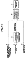
- Figs. 13 and 14 are block diagrams showing other embodiments of the present invention.
- Fig. 13 shows an apparatus for transmitting connecting status
- Fig. 14 shows an apparatus for generating connecting status display data.
- the same marks as in Figs. 1 and 2 are given to the same components in order to simplify the description.
- connection display data generating circuit 41 is adopted instead of the connection display data generating circuit 4.
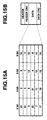
- Figs. 15A, 15B and 16 illustrate the connection display data generating circuit 41 and the formatting 5.
- Fig. 15A shows a connection display data format
- Fig. 15B shows a transmission data format.
- Fig. 16 shows a status of 24 nodes, from node #0 to node #23, connected on a bus.
- a port number is expressed with a figure following a mark (p).
- Each of nodes #0 to #23 is allotted from 0 to 23 as its node ID according to the method of distinguishing node ID.
- the node whose node ID is 23 is a root.
- the parent node ID list generating circuit 3 generates a parent node ID list shown in Table 5 below expressing the correspondence of ID between nodes and their parent nodes.
- Node ID 0 1 2 3 4 5 6 7 8 9 10 11
- connection display data generating circuit 41 sequences node IDs on the basis of results of the parent node ID list. That is, the connection display data generating circuit 41 sequences node IDs so that the receiving side becomes able to display hierarchical connecting status using rules that a root has a highest ID value, a lower ID number is given to a leaf first, and a parent always has a higher ID value than its child does.
- connection display data generating circuit 41 arranges 23, the node ID of a root, first at the head, then, node IDs of child nodes of the node #23 in order of lower number. Since Table 5 shows that node #23 has child nodes, nodes #3, #9, #10, #22 whose node IDs are 3, 9, 10, 22 respectively, 23 showing node ID is followed by 3, 9, 10 and 22 in arrangement.
- node IDs of child nodes are arranged in order of lower node ID.
- nodes #0, #1, #2 whose node ID is 0, 1, 2 respectively.
- node IDs are arranged in this order.
- nodes #9 are, according to Table 5, nodes #5, #8 whose node ID is 5, 8 respectively, node IDs 5, 8 are arranged in this order.
- the next node #10 has no child node as shown in Table 5.
- Node IDs of child nodes of node #22 are, according to Table 5, 13, 18, 20 and 21.
- connection display data generating circuit 41 arranges node IDs in order of node IDs 23, 3, 9, 10, 22, 0, 1, 2, 5, 8, 13, 18, 20 and 21.
- connection display data generating circuit 41 sequnces node IDs in a similar way. That is, the connection display data generating circuit 41 next looks into child nodes of nodes in order of nodes #0, #1, #2, #5, #13, #18, #20, #21, and arranges found node IDs of child nodes in order of lower node ID.
- connection display data generating circuit 41 arranges node IDs in order of node IDs 23, 3, 9, 10, 22, 0, 1, 2, 5, 8, 13, 18, 20, 21, 4, 6, 7, 11, 12, 14, 17, 19, 15 and 16 according Table 5.
- connection display data generating circuit 41 arranges sequenced node IDs in 8 bits as shown in Fig. 15A, and outputs them as connection display data to the formatting 5.
- Fig. 15B shows a configuration of an asynchronous packet of IEEE 1394.
- An asynchronous packet is composed of a header, a header CRC, data and data CRC arranged.
- the formatting 5 arranges connection display data at the part for data of an asynchronous packet of IEEE 1394.
- the formatting 5 is designed to arrange connection display data in an asynchronous packet before transmitting them.
- Transmission data from the formatting 5 are supposed to be sent to an IEEE 1394 bus, which is not shown, through the terminal 6. It is designed so that connection display data from the connection display data generating circuit 41 are also able to be outputted as they are through the terminal 7.
- FIG. 14 differs from that shown in Fig. 2 only in point of that a connecting status image data generating circuit 42 is adapted instead of the connecting status image data generating circuit 12.
- transmission data transmitted through an IEEE 1394 bus are, similarly to the embodiment shown in Fig. 2, supplied to the transmission data decoding circuit 11 through the terminal 9.
- the transmission data decoding circuit 11 is designed to depacket inputted asynchronous packets, and to supply connection display data, which have been arranged in the part for data, to the connecting status image data generating circuit 42.
- connection display data may be inputted to the terminal 10.
- connection display data from the terminal 10 are directly supplied to the connecting status image data generating circuit 42, similarly to the embodiment shown in Fig. 2.
- the connecting status image data generating circuit 42 is designed to generate, out of inputted connection display data, image data to show connecting status of a network, and to supply the data to the displaying circuit 13.
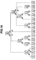
- Fig. 17 illustrates the connecting status image data generating circuit 42 shown in Fig. 14.
- Fig. 17 corresponds to the connection display data shown in Fig. 15A.
- the connecting status image data generating circuit 42 when connection display data shown in Fig. 15A are inputted, generates image data to indicate the connecting status display shown in Fig. 17.
- the connecting status image data generating circuit 42 generates the connecting status display shown in Fig. 17, using the rules that; a root has a highest ID value, a lower ID number is given to a leaf first, and ID value of a parent is always higher than that of its child.
- connection display data shown in Fig. 15A have node values of 23, 3, 9, 10, 22, 0, 1, 2, 5, 8, 13, 18, 20, 21, 4, 6, 7, 11, 12, 14, 17, 19, 15, and 16 arranged in this order.
- the part where lower node IDs than preceding node IDs are arranged is a breakpoint of a hierarchy. That is, in the example shown in Fig. 15A, breakpoints of hierarchy exist at 23 ⁇ 3, 22 ⁇ 0, 21 ⁇ 4, and 19 ⁇ 15.
- Node ID 23 has the highest ID value showing that it is a root.
- the connecting status image data generating circuit 42 decides the hierarchy for nodes #0 to #23, expressed with node IDs 0 to 23 respectively, to belong to.
- node #23, a root belongs to the 1st layer of hierarchy, nodes #3, #9, #10, and #22 to the 2nd layer of hierarchy, nodes #0, #1, #2, #5, #8, #13, #18, #20, and #21 to the 3rd layer of hierarchy, nodes #4, #6, #7, #11, #12, #14, #17, and #19 to the 4th layer of hierarchy, and nodes #15, #16 belong to the 5th layer of hierarchy.
- the connecting status image data generating circuit 42 as shown in Fig. 17, generates a connecting status display to show each of nodes allotted to each of hierarchies, from the 1st to the 5th hierarchy.
- the connecting status image data generating circuit 42 decides a node, which is in an upper layer, for a node in each hierarchy to be connected, that is, decides a node to be a parent node of each node.
- the connecting status image data generating circuit 42 decides a parent node for a node in each hierarchy by finding a node in one upper layer having a higher node ID than the node.
- nodes #3, #9, #10, #22 are nodes in the 2nd hierarchy.
- nodes with lower node IDs than 3 are child nodes of node #3.
- Nodes belonging to the 3rd hierarchy are nodes #0, #1, #2, #5, #8, #13, #18, #20, #21, and nodes #0, #1, #2 are found to be child nodes of node #3.
- Child nodes of node #9 should be nodes in the 3rd hierarchy having node IDs higher than that of node #3 and lower than that of node #9. That is, child nodes of node #9 are nodes #5 and #8.
- the connecting status image data generating circuit 42 looks into child nodes of all nodes, and displays a diagram to express parentage as shown in Fig. 17.
- the connecting status image data generating circuit 42 is designed to output image data to display a connecting status list shown in Fig. 17.
- the connecting status image data generating circuit 42 can, similarly to the embodiment shown in Fig. 1, generate, using device information, image data to display names and icons of devices, which are provided by device information, instead of box display to express nodes.
- the displaying circuit 13 is designed to display images on the basis of image data from the connecting status image data generating circuit 42.
- the formatting 5 and the transmission data decoding circuit 11 can be realized by the physical and link layer 25 and the transaction layer 26.
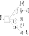
- Fig. 18 illustrates an example of image display by the displaying circuit 13.
- connection display data and transmission data by a position of each circuit in a network, becomes the same as shown in Figs. 8 through 10 above mentioned.
- the flow of connection display data and transmission data becomes the one shown in Fig. 8.
- connection display data and connecting status image data are similar to the embodiments shown in Figs. 1 and 2.
- connection display data generating circuit 41 generates connection display data on the basis of the parent node ID list, and outputs them from the terminal 7.
- Connection display data inputted trough the terminal 10 are supplied to the connecting status image data generating circuit 42.
- the connecting status image data generating circuit 42 generates image data to show hierarchical displays of connecting status of a network on the basis of connection display data.
- connection display data correspond to Fig. 15A.
- the connecting status image data generating circuit 42 decides that the parts, where values of node IDs sequentially rise, belong to a same hierarchy, and that the parts, where node IDs fall discontinuously, that is, in a data sequence, where lower node IDs than preceding node IDs are arranged, are breakpoints and arranges nodes in each hierarchy.
- the connecting status image data generating circuit 42 next, decides on nodes in each hierarchy that, among nodes in a hierarchy one stage above the one a node is in, one node having a higher node ID than the node does is its parent node, and seeks for parentage of each node. In this way, the connecting status image data generating circuit 42 generates image data to display the connecting status display shown in Fig. 17 giving hierarchy and the parentage of each node.
- the image data are supplied to the displaying circuit 13 (not shown), and the connecting status display shown in Fig. 17 is displayed on the screen. With this display, users can easily secure present hierarchical connecting status.
- device information may be transmitted from each node through an IEEE 1394 bus.
- This device information is supplied to the displaying part 31 of the display layer 24 through the physical and link layer 25, the transaction layer 26 and the API 23 to be supplied to the connecting status image data generating circuit 42 which forms the displaying part 31.
- the connecting status image data generating circuit 42 generates, using the inputted device information, image data to display names and icons of devices instead of the display to show each node shown in Fig. 17.
- Fig. 18 shows a display on the display screen of the displaying circuit 13. It should be added that the example in Fig. 18 is not the one corresponding to Fig. 17.
- the root is a television receiver to which a notebook-type personal computer, a DV deck and a set-top box are connected in the 2nd hierarchy, in the 3rd hierarchy, a DVD-ROM, a printer, a camcorder, an amplifier and a CD changer are connected, in the 4th hierarchy, a PC camera and a D-VHS video tape recorder are connected. Parentage of each node is shown with lines connecting icons of each node.
- topology map 1 In connection with the embodiment shown in Figs. 1 and 2, it is not necessary to have all of the topology map 1, the connecting information read circuit 2, the parent node ID list generating circuit 3, the connection display data generating circuit 41, the connecting status image data generating circuit 42 and the displaying circuit 13, shown in Figs. 13 and 14, provided on devices of a same node. It is apparent, for example, that a topology map may be on another node, or functions of these circuits may be realized by a circuit other than the bus managing part 27 or by software.
- the node 32 does not have to have a displaying part.
- functions of each circuit shown in Fig. 13 can be realized by, for example, the bus managing part 27 or others.
- existence of the node 33 on a network will be of use, because, though it has no functions of each circuit in Fig. 13, it has the displaying part 31 to realize functions of the connecting status image data generating circuit 42 shown in Fig. 14.
- the bus managing part 27 in Fig. 9 generates, on the basis of information of a topology map, a parent node ID list corresponding to the Table 5 and then, generates connection display data on the basis of this parent node ID list.
- the connection display data are supplied to the transaction layer 26 and the physical and link layer 25 to be converted by the formatting 5, shown in Fig. 13 and a function thereof, into a transmission data format corresponding to IEEE 1394.
- the connection display data are arranged in the part for data in an asynchronous packet.
- Transmission data from the physical and link layer 25 are transmitted to the node 33 shown in Fig. 10 through an IEEE 1394 bus.
- the node 33 fetches connection display data from transmission data by the transmission data decoding circuit 11 (shown in Fig. 14) which is a function of the physical and link layer 25.
- the connection display data are supplied to the displaying part 31 of the display layer 24 through the API 23.
- the image data are given to the displaying circuit 13, and the display shown in Fig. 17 appears on the screen.
- the connecting status image data generating circuit 42 of the displaying circuit 31 When the node 33 receives device information from other nodes through an IEEE 1394 bus, the connecting status image data generating circuit 42 of the displaying circuit 31 generates image data to display names and icons of devices instead of a display shown in Fig. 17.
- the transmitting side generates, on the basis of a topology map, a parent node ID list to show the correspondence of each node to its parent node, and converts information of this parent node ID list into connection display data in a predetermined data format giving consideration to displaying hierarchical connecting status.
- the connection display data are also supposed to be converted into a predetermined transmission data format before being transmitted.
- the receiving side is designed to obtain connection display data from transmission data or directly, and to generate, from the connection display data, image data to display hierarchical connecting status.
- Hierarchical connecting status can be displayed in the same format whatever device each node is, or even when the transmitting side and the receiving side are not on a same node, or displaying devices are different.
- This embodiment is highly effective when a display layer and an API are made common.
- displaying hierarchical connecting status allows to secure the hop count from a root easily, so as to prevent users from connecting devices exceeding the limit of hop count or to enable users easily to know devices connected exceeding the limit of hop count.
- a node having functions of the connecting status image data generating circuit 42 reads device information from other nodes
- each circuit shown in Figs. 13 and 14 may be formed in any node and any position in a node.
- each circuit shown in Figs. 13 and 14 may be realized by software.
- the connecting status image data generating circuit 42 and the displaying circuit 13 may exist on different nodes.
- it may be designed so that connection display data are written in a read/write memory space of a device of a predetermined node and the connection display data stored in this memory space are read by a node having the connecting status image data generating circuit 42.
Landscapes
- Engineering & Computer Science (AREA)
- Computer Networks & Wireless Communication (AREA)
- Signal Processing (AREA)
- Multimedia (AREA)
- Small-Scale Networks (AREA)
- Data Exchanges In Wide-Area Networks (AREA)
Applications Claiming Priority (6)
| Application Number | Priority Date | Filing Date | Title |
|---|---|---|---|
| JP323248/97 | 1997-11-25 | ||
| JP32324797A JP3471589B2 (ja) | 1997-11-25 | 1997-11-25 | 接続状況送信装置及び接続状況表示方法 |
| JP323247/97 | 1997-11-25 | ||
| JP32324897 | 1997-11-25 | ||
| JP32324897A JP3471590B2 (ja) | 1997-11-25 | 1997-11-25 | 接続状況送信装置、接続状況表示データ作成装置及び接続状況表示方法 |
| JP32324797 | 1997-11-25 |
Publications (2)
| Publication Number | Publication Date |
|---|---|
| EP0920156A2 true EP0920156A2 (fr) | 1999-06-02 |
| EP0920156A3 EP0920156A3 (fr) | 1999-08-04 |
Family
ID=26571109
Family Applications (1)
| Application Number | Title | Priority Date | Filing Date |
|---|---|---|---|
| EP98122156A Withdrawn EP0920156A3 (fr) | 1997-11-25 | 1998-11-25 | Dispositif pour transmettre des états de connection, dispositif pour générer des données associées d'affichage et procédé pour afficher celles-ci |
Country Status (3)
| Country | Link |
|---|---|
| US (2) | US6529951B1 (fr) |
| EP (1) | EP0920156A3 (fr) |
| KR (1) | KR19990044988A (fr) |
Cited By (6)
| Publication number | Priority date | Publication date | Assignee | Title |
|---|---|---|---|---|
| EP1061692A2 (fr) * | 1999-06-16 | 2000-12-20 | Sony Corporation | Dispositif de contrôle, système de transmission et méthode de contrôle |
| WO2001040945A2 (fr) * | 1999-12-01 | 2001-06-07 | Microsoft Corporation | Procede et appareil surs de debogage a distance de logiciels d'ordinateurs via un bus serie |
| EP1185034A2 (fr) * | 2000-08-29 | 2002-03-06 | Sony Corporation | Dispositif d'affichage d'erreurs dans un réseau, et procédé d'affichage de détection d'erreurs |
| EP1263169A1 (fr) * | 2001-05-22 | 2002-12-04 | Sony International (Europe) GmbH | Méthode d'évaluation d'information sur plusieurs noeux connectés à un réseau |
| US7343441B1 (en) | 1999-12-08 | 2008-03-11 | Microsoft Corporation | Method and apparatus of remote computer management |
| EP2618265A1 (fr) * | 2012-01-19 | 2013-07-24 | Acer Incorporated | Systèmes électroniques et procédés de gestion |
Families Citing this family (32)
| Publication number | Priority date | Publication date | Assignee | Title |
|---|---|---|---|---|
| US6466549B1 (en) * | 1999-04-12 | 2002-10-15 | Intel Corporation | Broadcast discovery in a network having one or more 1394 buses |
| US6826632B1 (en) * | 1999-05-18 | 2004-11-30 | Gateway, Inc. | System for identifying the interconnection of peripheral devices |
| US6772232B1 (en) * | 1999-08-26 | 2004-08-03 | Hewlett-Packard Development Company, L.P. | Address assignment procedure that enables a device to calculate addresses of neighbor devices |
| JP2001077835A (ja) * | 1999-08-31 | 2001-03-23 | Sony Corp | 情報通信方法及び装置 |
| JP2002077211A (ja) * | 2000-08-29 | 2002-03-15 | Canon Inc | 情報処理装置およびその方法、並びに、記録媒体 |
| US7940716B2 (en) | 2005-07-01 | 2011-05-10 | Terahop Networks, Inc. | Maintaining information facilitating deterministic network routing |
| US6973023B1 (en) * | 2000-12-30 | 2005-12-06 | Cisco Technology, Inc. | Method for routing information over a network employing centralized control |
| JP4719987B2 (ja) * | 2001-02-09 | 2011-07-06 | ソニー株式会社 | 画面表示制御方法、プログラムおよび画面表示制御装置 |
| US7690017B2 (en) | 2001-05-03 | 2010-03-30 | Mitsubishi Digital Electronics America, Inc. | Control system and user interface for network of input devices |
| JP4443225B2 (ja) * | 2001-11-23 | 2010-03-31 | トムソン ライセンシング | ブリッジを有する通信ネットワークにおける接続を管理する方法及び装置 |
| JP3647815B2 (ja) * | 2002-03-11 | 2005-05-18 | 株式会社東芝 | 通信方法および通信装置 |
| US7609612B2 (en) * | 2002-07-12 | 2009-10-27 | Texas Instruments Incorporated | Multi-carrier transmitter for ultra-wideband (UWB) systems |
| US11368537B2 (en) * | 2002-10-28 | 2022-06-21 | Dynamic Mesh Networks, Inc. | High performance wireless network |
| US7143207B2 (en) * | 2003-11-14 | 2006-11-28 | Intel Corporation | Data accumulation between data path having redrive circuit and memory device |
| JP2005157444A (ja) * | 2003-11-20 | 2005-06-16 | Toshiba Corp | Fifo制御回路 |
| US8421715B2 (en) * | 2004-05-21 | 2013-04-16 | Semiconductor Energy Laboratory Co., Ltd. | Display device, driving method thereof and electronic appliance |
| US7142107B2 (en) | 2004-05-27 | 2006-11-28 | Lawrence Kates | Wireless sensor unit |
| US7631042B2 (en) * | 2004-06-30 | 2009-12-08 | International Business Machines Corporation | Method to update status on multiple voice and text systems from a single device |
| JP3952053B2 (ja) * | 2004-09-21 | 2007-08-01 | 船井電機株式会社 | 接続管理プログラム |
| US7899864B2 (en) * | 2005-11-01 | 2011-03-01 | Microsoft Corporation | Multi-user terminal services accelerator |
| US20070150817A1 (en) * | 2005-12-23 | 2007-06-28 | Ducheneaut Nicolas B | User interface and method for composing services in a ubiquitous computing environment through direction and selection operators |
| US20090129306A1 (en) * | 2007-02-21 | 2009-05-21 | Terahop Networks, Inc. | Wake-up broadcast including network information in common designation ad hoc wireless networking |
| KR100780072B1 (ko) * | 2006-05-03 | 2007-11-29 | 오렌지로직 (주) | 무선 개인영역 네트워크에서의 하위 노드 관리 방법 및장치 |
| US7720542B2 (en) * | 2006-07-17 | 2010-05-18 | Med-El Elektromedizinische Geraete Gmbh | Remote sensing and actuation of fluid in cranial implants |
| KR100746471B1 (ko) * | 2006-10-26 | 2007-08-06 | 주식회사 케이티 | 센서 노드 id 할당 방법 및 그를 이용한 계층적 센서네트워크 구성 방법 |
| WO2009140669A2 (fr) | 2008-05-16 | 2009-11-19 | Terahop Networks, Inc. | Fixation, surveillance et suivi de conteneur d'expédition |
| US8391435B2 (en) | 2008-12-25 | 2013-03-05 | Google Inc. | Receiver state estimation in a duty cycled radio |
| US8582450B1 (en) * | 2009-09-30 | 2013-11-12 | Shoretel, Inc. | Status reporting system |
| JP5950698B2 (ja) * | 2012-05-31 | 2016-07-13 | キヤノン株式会社 | 情報処理装置 |
| WO2016048263A1 (fr) | 2014-09-22 | 2016-03-31 | Hewlett Packard Enterprise Development Lp | Identification de limites de segment défini par du contenu |
| US10505843B2 (en) * | 2015-03-12 | 2019-12-10 | Dell Products, Lp | System and method for optimizing management controller access for multi-server management |
| US10429437B2 (en) * | 2015-05-28 | 2019-10-01 | Keysight Technologies, Inc. | Automatically generated test diagram |
Citations (4)
| Publication number | Priority date | Publication date | Assignee | Title |
|---|---|---|---|---|
| EP0637157A2 (fr) * | 1993-07-30 | 1995-02-01 | Canon Kabushiki Kaisha | Méthode et appareil de commande de système |
| US5504757A (en) * | 1994-09-27 | 1996-04-02 | International Business Machines Corporation | Method for selecting transmission speeds for transmitting data packets over a serial bus |
| EP0739110A2 (fr) * | 1995-04-19 | 1996-10-23 | Hewlett-Packard Company | Méthode de détermination de topologie d'un réseau |
| WO1997049057A2 (fr) * | 1996-06-21 | 1997-12-24 | Sony Electronics, Inc. | Dispositif d'interface utilisateur mettant en oeuvre une carte topologique |
Family Cites Families (19)
| Publication number | Priority date | Publication date | Assignee | Title |
|---|---|---|---|---|
| US587193A (en) * | 1897-07-27 | Mustache-sharer | ||
| JPH0827499B2 (ja) | 1987-12-03 | 1996-03-21 | 松下電器産業株式会社 | 立体テレビジョン用撮像装置 |
| US5724517A (en) * | 1994-09-27 | 1998-03-03 | International Business Machines Corporation | Method for generating a topology map for a serial bus |
| US5687319A (en) * | 1994-09-27 | 1997-11-11 | International Business Machines Corporation | Method and system for determining maximum cable segments between all possible node to node paths on a serial bus |
| JPH0916609A (ja) * | 1995-04-25 | 1997-01-17 | Matsushita Electric Ind Co Ltd | 文書検索装置及び文書検索方法 |
| JPH09282263A (ja) | 1996-04-12 | 1997-10-31 | Sony Corp | 電子機器及びその識別情報構成方法 |
| JP3131150B2 (ja) | 1996-06-04 | 2001-01-31 | 財団法人工業技術研究院 | 通信ネットワークのアクセスシステム及びインタフェース |
| JPH09330298A (ja) | 1996-06-13 | 1997-12-22 | Mitsubishi Electric Corp | パスワード登録方法、認証方法、パスワード更新方法、パスワード登録システム、認証システムおよびパスワード更新システム |
| US5883621A (en) * | 1996-06-21 | 1999-03-16 | Sony Corporation | Device control with topology map in a digital network |
| US5793366A (en) * | 1996-11-12 | 1998-08-11 | Sony Corporation | Graphical display of an animated data stream between devices on a bus |
| US6332159B1 (en) * | 1996-12-04 | 2001-12-18 | Canon Kabushiki Kaisha | Data communication system, apparatus and controlling method thereof |
| US6131119A (en) * | 1997-04-01 | 2000-10-10 | Sony Corporation | Automatic configuration system for mapping node addresses within a bus structure to their physical location |
| MY116734A (en) * | 1997-04-17 | 2004-03-31 | Matsushita Electric Ind Co Ltd | Image display device |
| CA2295759C (fr) * | 1997-06-25 | 2002-11-19 | Samsung Electronics Co., Ltd. | Procede et dispositif de creation de macros pour reseau domestique |
| JP3832937B2 (ja) * | 1997-08-26 | 2006-10-11 | キヤノン株式会社 | 制御装置 |
| US6160796A (en) * | 1998-01-06 | 2000-12-12 | Sony Corporation Of Japan | Method and system for updating device identification and status information after a local bus reset within a home audio/video network |
| US6003074A (en) * | 1998-02-24 | 1999-12-14 | Hewlett-Packard Company | Method and apparatus for mapping the physical topology of a subnetwork |
| US6810452B1 (en) * | 1999-03-19 | 2004-10-26 | Sony Corporation | Method and system for quarantine during bus topology configuration |
| US6826632B1 (en) * | 1999-05-18 | 2004-11-30 | Gateway, Inc. | System for identifying the interconnection of peripheral devices |
-
1998
- 1998-11-04 KR KR1019980047074A patent/KR19990044988A/ko not_active IP Right Cessation
- 1998-11-25 US US09/199,430 patent/US6529951B1/en not_active Expired - Fee Related
- 1998-11-25 EP EP98122156A patent/EP0920156A3/fr not_active Withdrawn
-
2002
- 2002-12-30 US US10/330,499 patent/US7058679B2/en not_active Expired - Fee Related
Patent Citations (4)
| Publication number | Priority date | Publication date | Assignee | Title |
|---|---|---|---|---|
| EP0637157A2 (fr) * | 1993-07-30 | 1995-02-01 | Canon Kabushiki Kaisha | Méthode et appareil de commande de système |
| US5504757A (en) * | 1994-09-27 | 1996-04-02 | International Business Machines Corporation | Method for selecting transmission speeds for transmitting data packets over a serial bus |
| EP0739110A2 (fr) * | 1995-04-19 | 1996-10-23 | Hewlett-Packard Company | Méthode de détermination de topologie d'un réseau |
| WO1997049057A2 (fr) * | 1996-06-21 | 1997-12-24 | Sony Electronics, Inc. | Dispositif d'interface utilisateur mettant en oeuvre une carte topologique |
Cited By (9)
| Publication number | Priority date | Publication date | Assignee | Title |
|---|---|---|---|---|
| EP1061692A2 (fr) * | 1999-06-16 | 2000-12-20 | Sony Corporation | Dispositif de contrôle, système de transmission et méthode de contrôle |
| EP1061692A3 (fr) * | 1999-06-16 | 2003-08-13 | Sony Corporation | Dispositif de contrôle, système de transmission et méthode de contrôle |
| WO2001040945A2 (fr) * | 1999-12-01 | 2001-06-07 | Microsoft Corporation | Procede et appareil surs de debogage a distance de logiciels d'ordinateurs via un bus serie |
| WO2001040945A3 (fr) * | 1999-12-01 | 2002-01-10 | Microsoft Corp | Procede et appareil surs de debogage a distance de logiciels d'ordinateurs via un bus serie |
| US7343441B1 (en) | 1999-12-08 | 2008-03-11 | Microsoft Corporation | Method and apparatus of remote computer management |
| EP1185034A2 (fr) * | 2000-08-29 | 2002-03-06 | Sony Corporation | Dispositif d'affichage d'erreurs dans un réseau, et procédé d'affichage de détection d'erreurs |
| EP1185034A3 (fr) * | 2000-08-29 | 2003-09-03 | Sony Corporation | Dispositif d'affichage d'erreurs dans un réseau, et procédé d'affichage de détection d'erreurs |
| EP1263169A1 (fr) * | 2001-05-22 | 2002-12-04 | Sony International (Europe) GmbH | Méthode d'évaluation d'information sur plusieurs noeux connectés à un réseau |
| EP2618265A1 (fr) * | 2012-01-19 | 2013-07-24 | Acer Incorporated | Systèmes électroniques et procédés de gestion |
Also Published As
| Publication number | Publication date |
|---|---|
| KR19990044988A (ko) | 1999-06-25 |
| US6529951B1 (en) | 2003-03-04 |
| EP0920156A3 (fr) | 1999-08-04 |
| US7058679B2 (en) | 2006-06-06 |
| US20030140135A1 (en) | 2003-07-24 |
Similar Documents
| Publication | Publication Date | Title |
|---|---|---|
| US6529951B1 (en) | Apparatus for transmitting connecting status and method of displaying connecting status | |
| US6122248A (en) | Data transmission system with bus failure recovery | |
| US6721818B1 (en) | Electronic device that stores information on its location based on information obtained from a node | |
| US6973087B2 (en) | Predictive time stamping of transmitted data | |
| Kunzman et al. | 1394 high performance serial bus: The digital interface for ATV | |
| US6446142B1 (en) | Method of and apparatus for dynamically binding subobjects into objects to represent functions and characteristics of a device within an IEEE 1394 serial bus network | |
| EP0932103A1 (fr) | Méthode et dispositif pour transférer des données bidirectionelles entre un bus IEEE 1394 et un appareil | |
| US6904049B1 (en) | Data transfer system and method for transferring data packets over an ATM link | |
| JPH10164107A (ja) | データ通信方法、電子機器、及び物理層集積回路 | |
| EP0959590B1 (fr) | Système de communication opérant à débit de données maximale | |
| US20020061025A1 (en) | Data transmitting and receiving apparatus and data transmitting and receiving method | |
| US5168496A (en) | System for internetwork communication between local areas networks | |
| US7903686B2 (en) | Connected device to be connected to an IEEE 1394 serial bus | |
| JP3471590B2 (ja) | 接続状況送信装置、接続状況表示データ作成装置及び接続状況表示方法 | |
| KR20000007567A (ko) | Ieee 1394 버스로 연결된 네트워크에서의 버스 리셋 처리방법 | |
| JP3471589B2 (ja) | 接続状況送信装置及び接続状況表示方法 | |
| EP1061692A2 (fr) | Dispositif de contrôle, système de transmission et méthode de contrôle | |
| US20070101042A1 (en) | Multimedia interface device, information processing method, corresponding information carrier and computer program | |
| KR100312065B1 (ko) | 서로 다른 노드간의 데이터 전송 방법 | |
| EP0932104B1 (fr) | Dispositif et méthode pour transférer des données bidirectionnelles entre un bus IEEE1394 et un appareil | |
| KR100297060B1 (ko) | 프로토콜 인터페이스 방법 | |
| CN118400308A (zh) | 一种报文的寻址方法、装置及可读存储介质 | |
| KR100336876B1 (ko) | 실시간 데이터 통신장치 | |
| KR100313769B1 (ko) | 등시성 데이터 제어방법 | |
| EP1263169B1 (fr) | Méthode d'évaluation d'information sur plusieurs noeux connectés à un réseau |
Legal Events
| Date | Code | Title | Description |
|---|---|---|---|
| PUAI | Public reference made under article 153(3) epc to a published international application that has entered the european phase |
Free format text: ORIGINAL CODE: 0009012 |
|
| 17P | Request for examination filed |
Effective date: 19981125 |
|
| AK | Designated contracting states |
Kind code of ref document: A2 Designated state(s): DE FR GB |
|
| AX | Request for extension of the european patent |
Free format text: AL;LT;LV;MK;RO;SI |
|
| PUAL | Search report despatched |
Free format text: ORIGINAL CODE: 0009013 |
|
| AK | Designated contracting states |
Kind code of ref document: A3 Designated state(s): AT BE CH CY DE DK ES FI FR GB GR IE IT LI LU MC NL PT SE |
|
| AX | Request for extension of the european patent |
Free format text: AL;LT;LV;MK;RO;SI |
|
| RIC1 | Information provided on ipc code assigned before grant |
Free format text: 6H 04L 12/40 A, 6H 04L 12/24 B |
|
| AKX | Designation fees paid |
Free format text: DE FR GB |
|
| STAA | Information on the status of an ep patent application or granted ep patent |
Free format text: STATUS: THE APPLICATION IS DEEMED TO BE WITHDRAWN |
|
| 18D | Application deemed to be withdrawn |
Effective date: 20000206 |