EP0918222A1 - Fahrtschreiber mit einem flachen, quaderförmigen Einbaugehäuse und einer herausziehbaren Druckerbaugruppe - Google Patents
Fahrtschreiber mit einem flachen, quaderförmigen Einbaugehäuse und einer herausziehbaren Druckerbaugruppe Download PDFInfo
- Publication number
- EP0918222A1 EP0918222A1 EP98120980A EP98120980A EP0918222A1 EP 0918222 A1 EP0918222 A1 EP 0918222A1 EP 98120980 A EP98120980 A EP 98120980A EP 98120980 A EP98120980 A EP 98120980A EP 0918222 A1 EP0918222 A1 EP 0918222A1
- Authority
- EP
- European Patent Office
- Prior art keywords
- tachograph
- front wall
- printer assembly
- wall element
- receptacle
- Prior art date
- Legal status (The legal status is an assumption and is not a legal conclusion. Google has not performed a legal analysis and makes no representation as to the accuracy of the status listed.)
- Granted
Links
Images


Classifications
-
- G—PHYSICS
- G07—CHECKING-DEVICES
- G07C—TIME OR ATTENDANCE REGISTERS; REGISTERING OR INDICATING THE WORKING OF MACHINES; GENERATING RANDOM NUMBERS; VOTING OR LOTTERY APPARATUS; ARRANGEMENTS, SYSTEMS OR APPARATUS FOR CHECKING NOT PROVIDED FOR ELSEWHERE
- G07C7/00—Details or accessories common to the registering or indicating apparatus of groups G07C3/00 and G07C5/00
-
- B—PERFORMING OPERATIONS; TRANSPORTING
- B41—PRINTING; LINING MACHINES; TYPEWRITERS; STAMPS
- B41J—TYPEWRITERS; SELECTIVE PRINTING MECHANISMS, i.e. MECHANISMS PRINTING OTHERWISE THAN FROM A FORME; CORRECTION OF TYPOGRAPHICAL ERRORS
- B41J15/00—Devices or arrangements of selective printing mechanisms, e.g. ink-jet printers or thermal printers, specially adapted for supporting or handling copy material in continuous form, e.g. webs
- B41J15/04—Supporting, feeding, or guiding devices; Mountings for web rolls or spindles
- B41J15/042—Supporting, feeding, or guiding devices; Mountings for web rolls or spindles for loading rolled-up continuous copy material into printers, e.g. for replacing a used-up paper roll; Point-of-sale printers with openable casings allowing access to the rolled-up continuous copy material
-
- G—PHYSICS
- G01—MEASURING; TESTING
- G01P—MEASURING LINEAR OR ANGULAR SPEED, ACCELERATION, DECELERATION, OR SHOCK; INDICATING PRESENCE, ABSENCE, OR DIRECTION, OF MOVEMENT
- G01P1/00—Details of instruments
- G01P1/12—Recording devices
- G01P1/122—Speed recorders
-
- G—PHYSICS
- G07—CHECKING-DEVICES
- G07C—TIME OR ATTENDANCE REGISTERS; REGISTERING OR INDICATING THE WORKING OF MACHINES; GENERATING RANDOM NUMBERS; VOTING OR LOTTERY APPARATUS; ARRANGEMENTS, SYSTEMS OR APPARATUS FOR CHECKING NOT PROVIDED FOR ELSEWHERE
- G07C5/00—Registering or indicating the working of vehicles
- G07C5/08—Registering or indicating performance data other than driving, working, idle, or waiting time, with or without registering driving, working, idle or waiting time
- G07C5/12—Registering or indicating performance data other than driving, working, idle, or waiting time, with or without registering driving, working, idle or waiting time in graphical form
Definitions
- the invention relates to a tachograph with a flat, cuboid Installation housing, with a display device and with arrangements for one Front entry and removal of driver-related data cards, with Keys for function control and for calling up memory contents of the Tachograph and with a printing device in which a band-shaped print carrier is used.
- the printing device requires one large and in view of the flat design of the installation housing unfavorable installation space.
- the object of the present invention was therefore in one Tachograph of the generic type to create a printing device, that meets the handling requirements and one for tachographs Standard series production with the least possible component expenditure and a high quality appropriate to the milieu.
- Protection claim 1 describes the solution to the problem advantageous embodiments of the invention emerge from the subclaims forth.
- the decisive advantage of the solution found is that the actual printing unit, a holder for the tape roll and one Element of the front wall of the tachograph a compact in which Tachograph slidably mounted printer assembly is formed for an insertion of a tape wrap no relative movement between the Printing unit and the recording for the tape wrap required.
- the proposed printer assembly allows for a complete and not easily detachably built-in housing, with one against the user aligned display device a convenient insertion of the tape wrap in the intended receptacle and threading the beginning of the tape in essentially from above. Due to the arched design it is suitable for the Access to the mount is only a relatively short stroke of the printer assembly required.
- the printing unit is fastened by clamping between the flange plate made in one piece with the receptacle and the Front wall element offers the smallest possible overall length. Furthermore this design enables a relatively short band section between the Tape wrap and the tear-off edge, which is threading the beginning of the tape relieved and moisture-related band stretching reduced.
- printer assembly is such is designed that they are in the front surface design of the Tachograph is integrated.
- front wall element is additional removed as a keyboard and assigned to the print carrier Provide guide means within the inaccessible from the outside Section between the pressure and transport roller and the Allow output slot to freely push through the beginning of the tape.
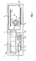
- FIG. 1 shows, the tachograph in question 1 cuboid installation housing, the front of which is covered by a panel or from one equipped to a functional assembly and front wall 2 connected to the installation housing in a suitable manner is formed.
- the front wall 2 are a window section 3 for one Tachograph 1 associated display device 4, keys 5 and 6 stored and openings 7 and 8 attached, which the input data cards assigned by drivers I or II.
- a recess 9 in the front wall 2 is provided, which is called a front wall element 10 designated aperture is covered.
- the front wall element fits 10 in terms of design, in particular flush with the front surface, into the front surface of the Tachograph 1.
- the front wall element 10 is a component of an following and to be described in more detail printer assembly and is consequently with a slot 11, which in cooperation with the Front surface of the front wall element 10
- the printer assembly in the tachograph 1 is slidably mounted and interacts with a suitable locking device. It serves the entire front wall element 10, which for this purpose with a sufficiently large free area or touch area 12 is provided as a button to actuate, that is to unlock the locking device. Further there are several buttons 13, 14, 15, 16 and 17 in the front wall element 10 stored so that the front wall element 10 at the same time as a keyboard is expanded.
- the display device 4 essentially serves to display the most important Working time data.
- the drivers have I and II assigned the buttons 13 and 15 and the menu button 6.
- the button's 14 and 16 serve the "forwards and backwards" in the for selected working time data type determined data records.
- button 5 With the button 5 in cooperation with one of the buttons 13 or 15 the respective Driver data card released for removal; button 17 turns on Printing process and the output of a document triggered.
- One also in the Front wall 10 formed socket 18 is used for connection for example a PC.
- Another connector is with a Cover 19 provided, which is secured by a seal 20. This Plug socket is provided for diagnostic and parameterization purposes.
- Figure 2 shows that the front wall element 10, on which the slot 11 and unspecified openings for the passage of the keys 13, 14, 15, 16 and 17 are formed, can be completed to a keyboard by a circuit board 22 by means of several screws , from one of which is denoted by 23, is fastened to the inside of the front wall element 10, with the interposition of a key mat 24 containing the keys 13, 14, 15, 16 and 17.
- the key mat is aligned and held 24 serving contours formed and formed on the circuit board 22 at least the buttons 13, 14, 15, 16 and 17 associated contact areas with suitable conductor tracks, which are not shown for the sake of simplicity.
- FIG. 1 A slot 27 formed in the housing 25 of a commercially available printing unit 26, which can be flanged to the front wall element 10, represents a channel for the passage of a ribbon cable assigned to the printed circuit board 22.
- 28 denotes a through hole made in the housing 25, which is a through hole on the Front wall element 10 trained threaded bolt 29 is assigned.
- the same purpose, namely the mutual alignment of front wall element 10 and housing 25 of printing unit 26, is served by a further threaded bolt, not shown in FIG. 2, to which a recess 30 provided on housing 25 is assigned.
- the assembly of the front wall element 10 and the printing unit 26 is carried out by screwing the front wall element 10 to a flange plate 31 using screws 32, 33 and 34.
- a flange plate 31 serving, unspecified, assigned approaches and Countersinks engaged.
- 35 with a slot in the flange plate 31 is designated, which serves to lead both the ribbon cable assigned to the circuit board 22 and lines connected to the printing unit.
- Columns 36 and 37 formed in the housing 25 represent the inlet and outlet openings for the print carrier 38 with respect to the printing unit 26.
- a lever designated 39 serves to lift the print head, preferably a thermal print head is provided from the pressure and transport roller when threading the print carrier 38.
- One molded onto the receptacle 42 Wall 46 is designed such that it from the tachograph 1st pulled out printer assembly 21 serves as a shield, that is, the Largely covers opening 9 and in this way penetration of Dirt in the tachograph 1 while inserting a tape wrap 43 prevented. Furthermore, it can be seen from FIG. 2 that at the Guide rail 41 a latch 47 is formed, the printer assembly 21 serves as a stop when pulled out.
- One labeled 48 Switching element is provided for latching the printer assembly 21.
- the flange plate 31, the receptacle 42 and the guide rails 40, 41 which are essentially in the form of an H profile, form a single and relatively rigid component.
- the grooves formed opposite one another in the guide rails 40, 41, of which a 51 or 52 is visible in FIG. 2, are used in a fixed position in the tachograph 1, essentially C-profiled holding rails, one of which is visible in FIG. 3 and designated 53 is as a guide.
- Driver pins 54 and 55 arranged in pairs on the guide rails 40, 41 are for a telescopic bearing of the printer assembly 21 is provided and are operatively connected to the intermediate rails 56 (FIG. 3).
- 57 is a cover, with 58 a side wall of the installation housing of the tachograph 1 to which the holding rail 53 is attached.
- the second parallel holding rail is associated with rigid supports connected to the bottom of the installation housing.
- One of the supports is visible in FIG. 3 and is designated 59.
- An arm 60 is formed on the last-mentioned holding rail, which serves as a stop and, as shown in FIG. 3, cooperates with the latch 47 in the position of the printer assembly 21 shown.
- the opening 9 when the printer module 21 is pulled out, is covered both by the wall 46 and by an apron 61 which is also integrally formed on the receptacle 42.
- the apron 61 in that a suitable opening is formed in it, additionally serves as a holder for a line bundle 62, which the flat ribbon cable 64, which has already been contacted with the printed circuit board 22 via a connecting plug 63, preferably a ribbon cable 65 for controlling the printing elements of the print head 66, Cables 67 for the power supply of a motor, not shown, for the transport of the print carrier 38, as well as cables for sensors, also not shown, which monitor the transport of the print carrier 38. 68 with a tongue 44 which is resiliently formed on the bottom 44 of the receptacle and which serves to relieve the strain, the train being connected to means which are not shown, in order to jam the printer module 21 in a suitable manner inside the tachograph 1.
- the pivotably mounted print head 66 can be lifted off the pressure and transport roller 69 by means of the lever 39 in order to thread the print carrier 38.
- the pressure and transport roller 69 is driven via a drive (not shown) by the motor already mentioned, which is arranged in the housing 25 of the printing unit 26.
- guide means are formed on the front wall element 10, which means 38 when threading a pressure carrier ensure the necessary automatic alignment of the beginning of the tape on the slot 11.
- These are parallel-shaped lamella rows 70 and 71 as well as side guides 72. The solution found thus offers sufficient ease of handling when inserting the tape roll 43, it requires the available installation space, it is suitable for series production and it is structured aesthetically in the front design of the tachograph 1.
Landscapes
- Physics & Mathematics (AREA)
- General Physics & Mathematics (AREA)
- Time Recorders, Dirve Recorders, Access Control (AREA)
- Pens And Brushes (AREA)
- Dry Shavers And Clippers (AREA)
Abstract
Description
Es zeigen:
- Figur 1
- eine Frontansicht eines Fahrtschreibers der erfindungsgemäßen Art,
- Figur 2
- eine Explosionsdarstellung der Druckerbaugruppe.
- Figur 3
- eine Seitenansicht und Teilschnittdarstellungen des Fahrtschreibers gemäß Figur 1 mit herausgezogener Druckerbaugruppe,
denen eine mit 23 bezeichnet ist, an der Innenseite des Frontwandelementes 10 befestigt wird, und zwar unter Zwischenlage einer die Tasten 13, 14, 15, 16 und 17 beinhaltenden Tastenmatte 24. Dabei sind an der Innenseite des Frontwandelementes 10 dem Ausrichten und Haltern der Tastenmatte 24 dienende Konturen ausgeformt und auf der Leiterplatte 22 wenigstens den Tasten 13, 14, 15, 16 und 17 zugeordnete Kontaktflächen mit geeigneten Leiterbahnen ausgebildet, die der Einfachheit halber nicht dargestellt sind. Ebenso ist in der Figur 2 auf die Darstellung einer der Leiterplatte 22 zugeordneten elektrischen Verbindung verzichtet. Ein im Gehäuse 25 eines handelsüblichen Druckwerkes 26, welches an das Frontwandelement 10 anflanschbar ist, ausgebildeter Schlitz 27, stellt einen Kanal zur Durchführung eines der Leiterplatte 22 zugeordneten Flachbandkabels dar. Mit 28 ist eine in dem Gehäuse 25 angebrachte Durchgangsbohrung bezeichnet, welcher ein an dem Frontwandelement 10 ausgebildeter Gewindebolzen 29 zugeordnet ist. Dem selben Zweck, nämlich dem gegenseitigen Ausrichten von Frontwandelement 10 und Gehäuse 25 des Druckwerkes 26 dient ein weiterer, in Figur 2 nicht sichtbarer Gewindebolzen, dem eine am Gehäuse 25 vorgesehene Aussparung 30 zugeordnet ist. Das Zusammenfügen von Frontwandelement 10 und Druckwerk 26 erfolgt durch Verschrauben des Frontwandelementes 10 mit einer Flanschplatte 31 unter Verwendung von Schrauben 32, 33 und 34. Dabei gehen als Ausrichtmittel zwischen dem Druckwerk 26 und der Flanschplatte 31 dienende, nicht näher bezeichnete, einander zugeordnete Ansätze und Senkungen in Eingriff. Mit 35 ist ein in der Flanschplatte 31 angebrachter Schlitz bezeichnet, der der Durchführung sowohl des der Leiterplatte 22 zugeordneten Flachbandkabels als auch von mit dem Druckwerk verbundenen Leitungen dient. Im Gehäuse 25 ausgebildete Spalte 36 bzw. 37 stellen bezogen auf das Druckwerk 26 die Einlauf- und die Auslauföffnung für den Druckträger 38 dar. Ein mit 39 bezeichneter Hebel dient dem Anheben des Druckkopfes, vorzugsweise ist ein Thermodruckkopf vorgesehen, von der Andrück- und Transportwalze beim Einfädeln des Druckträgers 38.
eine teleskopische Lagerung der Druckerbaugruppe 21 vorgesehen und stehen mit mitlaufenden Zwischenschienen 56 (Figur 3) in Wirkverbindung. Mit 57 ist ein Deckel, mit 58 eine Seitenwand des Einbaugehäuses des Fahrtschreibers 1 bezeichnet an welcher die Halteschiene 53 befestigt ist. Der zweiten parallel liegenden Halteschiene sind mit dem Boden des Einbaugehäuses verbundene, biegesteife Stützen zugeordnet. In Figur 3 ist eine der Stützen sichtbar und mit 59 bezeichnet. An der zuletzt erwähnten Halteschiene ist ein Arm 60 angeformt, der als Anschlag dient und, wie die Figur 3 zeigt, in der dargestellten Position der Druckerbaugruppe 21 mit dem Riegel 47 zusammenwirkt. Außerdem geht aus der Figur 3 hervor, daß die Öffnung 9 bei herausgezogener Druckerbaugruppe 21 sowohl von der Wand 46 als auch von einer ebenfalls an der Aufnahme 42 angeformten Schürze 61 abgedeckt ist. Die Schürze 61 dient, indem in ihr eine geeignete Öffnung ausgebildet ist, zusätzlich als Halterung für ein Leitungsbündel 62, welches das bereits erwähnte mit der Leiterplatte 22 über einen Verbindungsstecker 63 kontaktierte Flachbandkabel 64, ein vorzugsweise Flachbandkabel 65 zur Ansteuerung der Druckelemente des Druckkopfes 66, Leitungen 67 zur Stromversorgung eines dem Transport des Druckträgers 38 dienenden nicht dargestellten Motors sowie Leitungen zu ebenfalls nicht dargestellten Sensoren, die den Transport des Druckträgers 38 überwachen, umfaßt. Mit 68 ist eine am Boden 44 der Aufnahme 42 federnd angeformte Zunge bezeichnet, die der Zugentlastung dient, wobei der Zug im Zusammenhang steht mit nicht dargestellten Mitteln, um in geeigneter Weise beim Einschieben der Druckerbaugruppe 21 im Innern des Fahrtschreibers 1 zu stauen. Wie bereits erwähnt kann der schwenkbar gelagerte Druckkopf 66 mittels des Hebels 39 von der Andrück- und Transportwalze 69 zum Einfädeln des Druckträgers 38 abgehoben werden. Der Antrieb der Andrück- und Transportwalze 69 erfolgt über ein nicht dargestelltes Laufwerk durch den bereits erwähnten im Gehäuse 25 des Druckwerkes 26 angeordneten Motor. Der Vollständigkeit halber sei noch erwähnt, daß an dem Frontwandelement 10 Führungsmittel ausgebildet sind, die beim Einfädeln eines Druckträgers 38
das notwendige selbsttätige Ausrichten des Bandanfangs auf den Schlitz 11 gewährleisten. Es handelt sich dabei um parallel ausgeformte Lamellenreihen 70 und 71 sowie Seitenführungen 72. Die gefundene Lösung bietet somit eine ausreichend gute Handhabbarkeit beim Einsetzen des Bandwickels 43, sie kommt mit dem zur Verfügung stehenden Bauraum aus, sie ist für die Serienfertigung geeignet und sie gliedert sich ästhetisch in die frontseitige Gestaltung des Fahrtschreibers 1 ein.
Claims (10)
- Fahrtschreiber mit einem flachen, quaderförmigen Einbaugehäuse, mit einer Anzeigeeinrichtung und mit Vorkehrungen für eine frontseitige Eingabe und Entnahme von fahrerbezogenen Datenkarten, mit Tasten zur Funktionssteuerung und zum Aufrufen von Speicherinhalten des Fahrtschreibers sowie mit einer Druckvorrichtung, in welcher ein bandförmiger Druckträger Anwendung findet
dadurch gekennzeichnet,daß ein Element (10) der Frontwand (2) des F ahrtschreibers (1), das Druckwerk (26) und eine Aufnahme (42) für den Bandwickel (43) zu einer Druckerbaugruppe (21) zusammengefügt sind unddaß die Druckerbaugruppe (21) in dem Fahrtschreiber (1) derart verschiebbar gelagert ist, daß sie aus dem Fahrtschreiber (1) wenigstens teilweise herausziehbar ist. - Fahrtschreiber nach Anspruch 1,
dadurch gekennzeichnet,daß die Aufnahme (42) für den Bandwickel (43) an einer die Druckerbaugruppe (21) tragenden Flanschplatte (31) angeformt ist. - Fahrtschreiber nach Anspruch 2,
dadurch gekennzeichnet,daß die Aufnahme (42) als Schale mit am Boden (44) federnd angeformten Lagerschenkeln (45) ausgebildet ist. - Fahrtschreiber nach Anspruch 2,
dadurch gekennzeichnet, daß rechtwinklig zur Flanschfläche (31) und im wesentlichen seitenbündig mit der Flanschplatte (31) an dieser Führungsschienen (40, 41) ausgebildet sind. - Fahrtschreiber nach Anspruch 1,
dadurch gekennzeichnet,daß das Frontwandelement (10) wenigstens einen dem Durchführen des Druckträgers (38) dienenden Schlitz (11) aufweist,daß an dem Frontwandelement (10) dem Druckträger (38) zugeordnete Führungsmittel (70, 71, 72) ausgebildet sind, unddaß Vorkehrungen getroffen sind für das Befestigen des Frontwandelementes (10) an der Flanschplatte (31). - Fahrtschreiber nach Anspruch 5,
dadurch gekennzeichnet,daß in dem Frontwandelement (10) wenigstens eine Taste (13, 14, 15, 16, 17) gelagert ist unddaß die der Taste (13, 14, 15, 16, 17) zugeordneten Kontakte auf einer mit dem Frontwandelement (10) rückseitig verbundenen Leiterplatte (22) aufgebracht sind. - Fahrtschreiber nach Anspruch 1,
dadurch gekennzeichnet,daß zur Lagerung der Druckerbaugruppe (21) teleskopisch in Wirkverbindung stehende Führungsmittel (40, 41, 53, 54, 55, 56) vorgesehen sind. - Fahrtschreiber nach Anspruch 3,
dadurch gekennzeichnet, daß die eine Wand der Aufnahme (42) derart ausgebildet ist, daß sie, die durch die Verschiebbarkeit der Druckerbaugruppe (21) erforderliche Öffnung (9) in der Frontwand (2) des Fahrtschreibers (1) beim Wechseln des Bandwickels (43) weitgehend abdeckt. - Fahrtschreiber nach Anspruch 1,
dadurch gekennzeichnet,daß der Druckerbaugruppe (21) eine Ver- und Entriegelungseinrichtung zugeordnet ist, wobei das Frontwandelement (10) als Betätigungselement dient. - Fahrtschreiber nach Anspruch 1,
dadurch gekennzeichnet,daß der Druckerbaugruppe (21) als Ver- und Entriegelungseinrichtung ein bistabiles Rastgetriebe zugeordnet ist.
Applications Claiming Priority (2)
| Application Number | Priority Date | Filing Date | Title |
|---|---|---|---|
| DE29720521U DE29720521U1 (de) | 1997-11-19 | 1997-11-19 | Fahrtschreiber mit einem flachen, quaderförmigen Einbaugehäuse |
| DE29720521U | 1997-11-19 |
Publications (2)
| Publication Number | Publication Date |
|---|---|
| EP0918222A1 true EP0918222A1 (de) | 1999-05-26 |
| EP0918222B1 EP0918222B1 (de) | 2002-01-30 |
Family
ID=8048837
Family Applications (1)
| Application Number | Title | Priority Date | Filing Date |
|---|---|---|---|
| EP98120980A Expired - Lifetime EP0918222B1 (de) | 1997-11-19 | 1998-11-05 | Fahrtschreiber mit einem flachen, quaderförmigen Einbaugehäuse und einer herausziehbaren Druckerbaugruppe |
Country Status (7)
| Country | Link |
|---|---|
| EP (1) | EP0918222B1 (de) |
| JP (1) | JP4184505B2 (de) |
| BR (1) | BR9804694A (de) |
| CZ (1) | CZ293571B6 (de) |
| DE (2) | DE29720521U1 (de) |
| ES (1) | ES2172078T3 (de) |
| PL (1) | PL188723B1 (de) |
Cited By (12)
| Publication number | Priority date | Publication date | Assignee | Title |
|---|---|---|---|---|
| EP1184667A3 (de) * | 2000-09-01 | 2004-04-14 | Siemens Aktiengesellschaft | Fahrtschreiber mit zwei in einer Ebene angeordneten Lese-/Schreibaggregaten für Datenkarten |
| EP1103928A3 (de) * | 1999-11-27 | 2005-01-19 | Siemens Aktiengesellschaft | Fahrtschreiber mit einer Druckvorrichtung |
| EP1103927A3 (de) * | 1999-11-27 | 2005-02-09 | Siemens Aktiengesellschaft | Fahrschreiber mit einem flachen, einbaufähigen Gehäuse |
| EP1575000A1 (de) * | 2004-03-02 | 2005-09-14 | Delphi Technologies, Inc. | Tachograph mit wechselbarem Drucker |
| US7259776B2 (en) * | 2002-04-05 | 2007-08-21 | Siemens Ag | Tachograph with cubic housing and printing device |
| WO2008000576A1 (de) * | 2006-06-26 | 2008-01-03 | Continental Automotive Gmbh | Fahrtschreiber für ein kraftfahrzeug |
| EP1840843A3 (de) * | 2006-03-30 | 2010-01-13 | Continental Automotive GmbH | Fahrtschreiber für ein Kraftfahrzeug und Papierrolle für einen solchen Fahrtschreiber |
| DE102008033928A1 (de) * | 2008-07-18 | 2010-01-21 | Continental Automotive Gmbh | Fahrtschreiber |
| WO2011020689A1 (de) * | 2009-08-20 | 2011-02-24 | Intellic Germany Gmbh | Kontrollgerät |
| US8867196B2 (en) | 2010-12-20 | 2014-10-21 | Continental Automotive Gmbh | Onboard information system for vehicles |
| EP2853405A1 (de) * | 2013-09-27 | 2015-04-01 | Seiko Instruments Inc. | Wärmedrucker der Schubladenart |
| US9189898B2 (en) | 2009-08-18 | 2015-11-17 | Continental Automotive Gmbh | Tachograph having an interface for an external data input device |
Families Citing this family (7)
| Publication number | Priority date | Publication date | Assignee | Title |
|---|---|---|---|---|
| DE29812216U1 (de) * | 1998-07-09 | 1998-09-10 | Mannesmann VDO AG, 60388 Frankfurt | Fahrtschreiber mit einem quaderförmigen Einbaugehäuse und mit einer Druckvorrichtung |
| SE515600C2 (sv) * | 1998-10-16 | 2001-09-03 | Berifors Ab | Anordning för utskrift |
| DE29907171U1 (de) * | 1999-04-23 | 1999-07-01 | Mannesmann VDO AG, 60388 Frankfurt | Fahrtschreiber mit einem flachen, quaderförmigen Einbaugehäuse und einer quer zur Hochachse des Einbaugehäuses bewegbaren Druckvorrichtung |
| DE20101836U1 (de) | 2001-02-03 | 2001-04-05 | Mannesmann VDO AG, 60388 Frankfurt | Fahrtschreiber mit einem quaderförmigen Gehäuse und mit einer Druckvorrichtung |
| DE102004013160A1 (de) | 2004-03-17 | 2005-10-13 | Siemens Ag | Druckverfahren |
| DE102006026706A1 (de) * | 2006-06-08 | 2007-12-13 | Siemens Ag | Fahrtschreiber für ein Kraftfahrzeug |
| DE102007025169B3 (de) * | 2007-05-29 | 2009-01-08 | Continental Automotive Gmbh | Fahrtschreiber |
Citations (5)
| Publication number | Priority date | Publication date | Assignee | Title |
|---|---|---|---|---|
| EP0224616A1 (de) * | 1985-10-14 | 1987-06-10 | Carolyn Gelhorn | Vorrichtung zum Aufzeichnen von zur persönlichen oder gewerblichen Verwendung gefahrenen Entfernungen |
| EP0191413B1 (de) * | 1985-02-14 | 1991-12-18 | Mannesmann Kienzle GmbH | Fahrtschreiber für Kraftfahrzeuge |
| EP0624856A2 (de) * | 1993-05-12 | 1994-11-17 | VDO Adolf Schindling AG | Fahrtschreiber für Kraftfahrzeuge |
| EP0652129A1 (de) * | 1993-11-09 | 1995-05-10 | VDO Adolf Schindling AG | Kraftfahrzeug mit einem Fahrtschreiber |
| DE19536515A1 (de) * | 1994-10-18 | 1996-04-25 | Yazaki Corp | Fahrtmesser |
-
1997
- 1997-11-19 DE DE29720521U patent/DE29720521U1/de not_active Expired - Lifetime
-
1998
- 1998-11-04 PL PL98329496A patent/PL188723B1/pl not_active IP Right Cessation
- 1998-11-05 ES ES98120980T patent/ES2172078T3/es not_active Expired - Lifetime
- 1998-11-05 DE DE59802950T patent/DE59802950D1/de not_active Expired - Lifetime
- 1998-11-05 EP EP98120980A patent/EP0918222B1/de not_active Expired - Lifetime
- 1998-11-17 JP JP32672198A patent/JP4184505B2/ja not_active Expired - Fee Related
- 1998-11-18 CZ CZ19983746A patent/CZ293571B6/cs not_active IP Right Cessation
- 1998-11-18 BR BR9804694-2A patent/BR9804694A/pt active Search and Examination
Patent Citations (5)
| Publication number | Priority date | Publication date | Assignee | Title |
|---|---|---|---|---|
| EP0191413B1 (de) * | 1985-02-14 | 1991-12-18 | Mannesmann Kienzle GmbH | Fahrtschreiber für Kraftfahrzeuge |
| EP0224616A1 (de) * | 1985-10-14 | 1987-06-10 | Carolyn Gelhorn | Vorrichtung zum Aufzeichnen von zur persönlichen oder gewerblichen Verwendung gefahrenen Entfernungen |
| EP0624856A2 (de) * | 1993-05-12 | 1994-11-17 | VDO Adolf Schindling AG | Fahrtschreiber für Kraftfahrzeuge |
| EP0652129A1 (de) * | 1993-11-09 | 1995-05-10 | VDO Adolf Schindling AG | Kraftfahrzeug mit einem Fahrtschreiber |
| DE19536515A1 (de) * | 1994-10-18 | 1996-04-25 | Yazaki Corp | Fahrtmesser |
Cited By (12)
| Publication number | Priority date | Publication date | Assignee | Title |
|---|---|---|---|---|
| EP1103928A3 (de) * | 1999-11-27 | 2005-01-19 | Siemens Aktiengesellschaft | Fahrtschreiber mit einer Druckvorrichtung |
| EP1103927A3 (de) * | 1999-11-27 | 2005-02-09 | Siemens Aktiengesellschaft | Fahrschreiber mit einem flachen, einbaufähigen Gehäuse |
| EP1184667A3 (de) * | 2000-09-01 | 2004-04-14 | Siemens Aktiengesellschaft | Fahrtschreiber mit zwei in einer Ebene angeordneten Lese-/Schreibaggregaten für Datenkarten |
| US7259776B2 (en) * | 2002-04-05 | 2007-08-21 | Siemens Ag | Tachograph with cubic housing and printing device |
| EP1575000A1 (de) * | 2004-03-02 | 2005-09-14 | Delphi Technologies, Inc. | Tachograph mit wechselbarem Drucker |
| EP1840843A3 (de) * | 2006-03-30 | 2010-01-13 | Continental Automotive GmbH | Fahrtschreiber für ein Kraftfahrzeug und Papierrolle für einen solchen Fahrtschreiber |
| WO2008000576A1 (de) * | 2006-06-26 | 2008-01-03 | Continental Automotive Gmbh | Fahrtschreiber für ein kraftfahrzeug |
| DE102008033928A1 (de) * | 2008-07-18 | 2010-01-21 | Continental Automotive Gmbh | Fahrtschreiber |
| US9189898B2 (en) | 2009-08-18 | 2015-11-17 | Continental Automotive Gmbh | Tachograph having an interface for an external data input device |
| WO2011020689A1 (de) * | 2009-08-20 | 2011-02-24 | Intellic Germany Gmbh | Kontrollgerät |
| US8867196B2 (en) | 2010-12-20 | 2014-10-21 | Continental Automotive Gmbh | Onboard information system for vehicles |
| EP2853405A1 (de) * | 2013-09-27 | 2015-04-01 | Seiko Instruments Inc. | Wärmedrucker der Schubladenart |
Also Published As
| Publication number | Publication date |
|---|---|
| BR9804694A (pt) | 1999-11-03 |
| JP4184505B2 (ja) | 2008-11-19 |
| CZ293571B6 (cs) | 2004-06-16 |
| PL188723B1 (pl) | 2005-04-29 |
| ES2172078T3 (es) | 2002-09-16 |
| CZ374698A3 (cs) | 1999-08-11 |
| DE29720521U1 (de) | 1998-05-14 |
| JPH11283064A (ja) | 1999-10-15 |
| DE59802950D1 (de) | 2002-03-14 |
| PL329496A1 (en) | 1999-05-24 |
| EP0918222B1 (de) | 2002-01-30 |
Similar Documents
| Publication | Publication Date | Title |
|---|---|---|
| EP0918222B1 (de) | Fahrtschreiber mit einem flachen, quaderförmigen Einbaugehäuse und einer herausziehbaren Druckerbaugruppe | |
| EP0313882B1 (de) | Datenkartenanordnung | |
| EP1103928B1 (de) | Fahrtschreiber mit einer Druckvorrichtung | |
| EP1205875A2 (de) | Aufnahmevorrichtung für Datenkarten | |
| EP1103927B1 (de) | Fahrtschreiber mit einem flachen, einbaufähigen Gehäuse | |
| EP0709683B1 (de) | Anordnung der Aufzeichnungsträger in einem Fahrtschreiber mit einem flachen Einbaugehäuse | |
| DE4315833A1 (de) | Fahrtschreiber für Kraftfahrzeuge | |
| EP1184667B1 (de) | Fahrtschreiber mit zwei in einer Ebene angeordneten Lese-/Schreibaggregaten für Datenkarten | |
| DE8902863U1 (de) | Datenkartenaufnahme | |
| EP0468236A1 (de) | Zählwerk, insbesondere für Gasmengenzähler | |
| EP0864137B1 (de) | Fahrtschreiber mit einer schublade | |
| DE69117893T2 (de) | Elektronische Schreibmaschine | |
| EP1479028B1 (de) | Chipkarten-aufnahmevorrichtung mit einem eine chipkarte halternden schlitten | |
| DE3934792A1 (de) | Drucker, insbesondere matrixnadeldrucker | |
| DE69027700T2 (de) | Kassettenbandaufzeichnungsgeräten enthalten ein Lademechanismus | |
| DE2740822C2 (de) | Fernsehempfänger mit Einschubfach | |
| EP1052514B1 (de) | Fahrtschreiber mit einem flachen, quaderförmigen Einbaugehäuse und einer quer zur Hochachse des Einbaugehäuses bewegbaren Druckvorrichtung | |
| EP0417616B1 (de) | Einrichtung zur Aufnahme eines transportablen, karten- oder plattenförmigen Datenspeichers | |
| EP1037161B1 (de) | Lese-/Schreibaggregat für Datenkarten | |
| EP0271001B1 (de) | Fahrtschreiber für Kraftfahrzeuge | |
| EP0522381B1 (de) | Instrumententräger für Kraftfahrzeuge | |
| DE4036403C1 (de) | ||
| DE2515983A1 (de) | Elektroantrieb fuer fensteroeffner u.dgl. | |
| DE29912060U1 (de) | Anordnung zum Abdecken einer Steckerfassung | |
| DE29701586U1 (de) | Anordnung zum Festspannen von Diagrammscheiben |
Legal Events
| Date | Code | Title | Description |
|---|---|---|---|
| PUAI | Public reference made under article 153(3) epc to a published international application that has entered the european phase |
Free format text: ORIGINAL CODE: 0009012 |
|
| AK | Designated contracting states |
Kind code of ref document: A1 Designated state(s): DE ES FR GB IT NL SE |
|
| AX | Request for extension of the european patent |
Free format text: AL;LT;LV;MK;RO;SI |
|
| 17P | Request for examination filed |
Effective date: 19990730 |
|
| AKX | Designation fees paid |
Free format text: DE ES FR GB IT NL SE |
|
| GRAG | Despatch of communication of intention to grant |
Free format text: ORIGINAL CODE: EPIDOS AGRA |
|
| 17Q | First examination report despatched |
Effective date: 20010119 |
|
| GRAG | Despatch of communication of intention to grant |
Free format text: ORIGINAL CODE: EPIDOS AGRA |
|
| GRAH | Despatch of communication of intention to grant a patent |
Free format text: ORIGINAL CODE: EPIDOS IGRA |
|
| GRAH | Despatch of communication of intention to grant a patent |
Free format text: ORIGINAL CODE: EPIDOS IGRA |
|
| GRAA | (expected) grant |
Free format text: ORIGINAL CODE: 0009210 |
|
| REG | Reference to a national code |
Ref country code: GB Ref legal event code: IF02 |
|
| AK | Designated contracting states |
Kind code of ref document: B1 Designated state(s): DE ES FR GB IT NL SE |
|
| REF | Corresponds to: |
Ref document number: 59802950 Country of ref document: DE Date of ref document: 20020314 |
|
| GBT | Gb: translation of ep patent filed (gb section 77(6)(a)/1977) |
Effective date: 20020407 |
|
| REG | Reference to a national code |
Ref country code: ES Ref legal event code: FG2A Ref document number: 2172078 Country of ref document: ES Kind code of ref document: T3 |
|
| PLBE | No opposition filed within time limit |
Free format text: ORIGINAL CODE: 0009261 |
|
| STAA | Information on the status of an ep patent application or granted ep patent |
Free format text: STATUS: NO OPPOSITION FILED WITHIN TIME LIMIT |
|
| 26N | No opposition filed | ||
| PGFP | Annual fee paid to national office [announced via postgrant information from national office to epo] |
Ref country code: ES Payment date: 20091123 Year of fee payment: 12 |
|
| PGFP | Annual fee paid to national office [announced via postgrant information from national office to epo] |
Ref country code: IT Payment date: 20091126 Year of fee payment: 12 Ref country code: GB Payment date: 20091119 Year of fee payment: 12 |
|
| REG | Reference to a national code |
Ref country code: NL Ref legal event code: TD Effective date: 20101130 Ref country code: NL Ref legal event code: SD Effective date: 20101130 |
|
| REG | Reference to a national code |
Ref country code: FR Ref legal event code: TP |
|
| GBPC | Gb: european patent ceased through non-payment of renewal fee |
Effective date: 20101105 |
|
| PG25 | Lapsed in a contracting state [announced via postgrant information from national office to epo] |
Ref country code: GB Free format text: LAPSE BECAUSE OF NON-PAYMENT OF DUE FEES Effective date: 20101105 |
|
| REG | Reference to a national code |
Ref country code: FR Ref legal event code: TP Owner name: CONTINENTAL AUTOMOTIVE GMBH, DE Effective date: 20111104 |
|
| PG25 | Lapsed in a contracting state [announced via postgrant information from national office to epo] |
Ref country code: IT Free format text: LAPSE BECAUSE OF NON-PAYMENT OF DUE FEES Effective date: 20101105 |
|
| REG | Reference to a national code |
Ref country code: ES Ref legal event code: FD2A Effective date: 20120110 |
|
| PG25 | Lapsed in a contracting state [announced via postgrant information from national office to epo] |
Ref country code: ES Free format text: LAPSE BECAUSE OF NON-PAYMENT OF DUE FEES Effective date: 20101106 |
|
| PGFP | Annual fee paid to national office [announced via postgrant information from national office to epo] |
Ref country code: DE Payment date: 20121130 Year of fee payment: 15 Ref country code: FR Payment date: 20121130 Year of fee payment: 15 |
|
| PGFP | Annual fee paid to national office [announced via postgrant information from national office to epo] |
Ref country code: SE Payment date: 20121120 Year of fee payment: 15 |
|
| PGFP | Annual fee paid to national office [announced via postgrant information from national office to epo] |
Ref country code: NL Payment date: 20121120 Year of fee payment: 15 |
|
| REG | Reference to a national code |
Ref country code: NL Ref legal event code: V1 Effective date: 20140601 |
|
| REG | Reference to a national code |
Ref country code: SE Ref legal event code: EUG |
|
| REG | Reference to a national code |
Ref country code: FR Ref legal event code: ST Effective date: 20140731 |
|
| PG25 | Lapsed in a contracting state [announced via postgrant information from national office to epo] |
Ref country code: DE Free format text: LAPSE BECAUSE OF NON-PAYMENT OF DUE FEES Effective date: 20140603 Ref country code: NL Free format text: LAPSE BECAUSE OF NON-PAYMENT OF DUE FEES Effective date: 20140601 Ref country code: SE Free format text: LAPSE BECAUSE OF NON-PAYMENT OF DUE FEES Effective date: 20131106 |
|
| REG | Reference to a national code |
Ref country code: DE Ref legal event code: R119 Ref document number: 59802950 Country of ref document: DE Effective date: 20140603 |
|
| PG25 | Lapsed in a contracting state [announced via postgrant information from national office to epo] |
Ref country code: FR Free format text: LAPSE BECAUSE OF NON-PAYMENT OF DUE FEES Effective date: 20131202 |