EP0917889A1 - Schlauchbrücke - Google Patents
Schlauchbrücke Download PDFInfo
- Publication number
- EP0917889A1 EP0917889A1 EP98203820A EP98203820A EP0917889A1 EP 0917889 A1 EP0917889 A1 EP 0917889A1 EP 98203820 A EP98203820 A EP 98203820A EP 98203820 A EP98203820 A EP 98203820A EP 0917889 A1 EP0917889 A1 EP 0917889A1
- Authority
- EP
- European Patent Office
- Prior art keywords
- hose
- bridge
- passage
- section
- sections
- Prior art date
- Legal status (The legal status is an assumption and is not a legal conclusion. Google has not performed a legal analysis and makes no representation as to the accuracy of the status listed.)
- Granted
Links
Images

Classifications
-
- A—HUMAN NECESSITIES
- A62—LIFE-SAVING; FIRE-FIGHTING
- A62C—FIRE-FIGHTING
- A62C33/00—Hose accessories
- A62C33/06—Hose or pipe bridges
Definitions
- the invention relates to a hose bridge for bridging a hose extending over a surface, for example a fire hose for conveying water for extinguishing purposes, which hose bridge has a passage for the hose and defines a support surface that can rest on the surface.
- Hose bridges are used for bridging (temporarily) laid out hoses in such a way that vehicles, such as lorries and fire engines, can cross the hoses without squashing these flat or damaging them.
- the hose bridges have an up and a down ramp, as a result of which the vehicles are able to drive over the hose without too much trouble.
- the aim of the invention is, therefore, to provide a hose bridge which can be used with hoses of a large diameter and which nevertheless has a simple, relatively low construction. Moreover, the hose bridge must be suitable for both small and large hoses. Said aim is achieved in that the transverse dimension of the passage in the hose bridge in a direction transverse to the supporting surface is smaller than the nominal diameter of the hose and the circumferential dimension of the passage essentially corresponds to the circumfcrential dimension of the hose.
- the hose can be accommodated in the passage without folds. As a result the flow in the hose is disrupted to a lesser extent, whilst no folding can occur and the hose will also not rapidly become damaged as a consequence of the deformation.
- the cross-section of the passage can be of various shapes. According to a simple embodiment, the transverse dimension of the passage in a direction parallel to the supporting surface is greater than said diameter.
- the hose bridge according to the invention can be of low height. As a consequence of this low height, the up and down ramps can remain short, such that traffic is not impeded to too great an extent.
- the hose is flattened by the hose bridge, which leads to a certain reduction in the surface area of the cross-section. Nevertheless, such a reduction does not result in too great an increase in resistance in the case of transport of fluid. This is because, in the case of laminar flows, the hose resistance is reasonably independent of the size of the surface area. However, the length of said surface that is embraced is important. Furthermore, it is found that a reduction in the surface area of the hose over a short distance compared with the total length of the hose has little influence on the transport flow.
- the flow in a hose changes from laminar flow to turbulent flow when the so-called critical flow rate is exceeded.
- the flow rate is therefore usually selected to be approximately 50 % of the critical flow rate. Even when such couplings are present, no change-over to turbulent flow occurs in that case.
- the passage is located in a bridge section, which bridge section has a supporting wall on that side of the passage which faces the supporting surface and has a bridging wall on the opposing side of the passage, which supporting wall has a larger contact surface with the hose than does the bridging wall.
- the hose located in the passage exerts a uniform pressure from one side on the adjoining wall.
- the bridge section will seek an equilibrium position which is shifted towards the supporting surface.
- the hose bridge is therefore also at the desired low level, that is to say with the supporting surface on the surface, if the hose is under overpressure.
- Such a larger contact surface of the supporting wall with the hose can, for example, be achieved if the supporting wall, viewed in the longitudinal direction of the passage, is longer than the bridging wall.
- the supporting wall facing the supporting surface has a descending, nose-shaped protrusion at its opposing ends in the longitudinal direction of the passage.
- the descending shape of the noses provides a gradual transition from the circular to the flattened cross-section of the hose.
- the hose bridge Preferably, it must be possible to fit the hose bridge later on over a hose that has already been run out.
- it has two shell sections which can be fitted laterally on the hose and can be fixed to one another against the resistance of the hose, which shell sections define a passage for the hose when they are fixed to one another.
- the shell sections can comprise a supporting shell section, which faces the supporting surface, and an opposing bridging shell section.
- the shell sections each have a supporting shell section half facing the supporting surface and an opposing bridging shell section half.
- Upward-sloping ramp sections are also provided, as well as a central bridge section in which the passage is located, which ramp sections are detachably coupled to the bridge section.
- bridge sections When the hose bridge is in use, several bridge sections can be provided one after the other in the longitudinal direction.
- a pair of ramp sections is connected to every two bridge sections, which bridge sections are a distance apart which corresponds to the track width of a road vehicle.
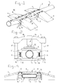
- Figure 1 shows a perspective view of a first embodiment of the hose bridge.
- Figure 2 shows a device for fitting the hose bridge.
- Figure 3 shows a cross-section along III-III in Figure 1.
- Figure 4 shows a longitudinal section along IV-IV in Figure 1.
- the hose bridge shown in Figure 1 is fitted over a hose 1, for example a fire hose.
- Said hose can, for example, have a cross-section of 20 cm.
- the hose bridge has two bridge sections 2, an up ramp 3 and a down ramp 4 being connected to each bridge section.
- An additional bridge section 2 can be fitted between the bridge sections 2 in order to keep the up-ramps and down-ramps 3, 4 the correct distance apart such that a vehicle can drive over the hose 1.
- the hose 1 is therefore compressed from the original circular shape to a flattened shape at the location of the hose bridge. It is true that such a flattened shape has a smaller flow cross-section than the normal circular shape, but the flow losses remain nevertheless restricted. In any event compared with the flow losses that already occur in a hose at the location of the couplings, no unjustifiably high losses occur at the location of the deformed cross-sections.
- the bridge section 2 consists of two parts, specifically a supporting wall 5 and a bridging wall 6.
- the supporting wall 5 has a supporting surface 7, by means of which the bridge section rests on the substrate.
- the bridging section 6 has a drivable surface 8, on which the wheels of a vehicle can be supported.
- the said components are firmly fixed to one another by means of studs 9 and nuts 10.
- the studs 9 are fixed to the supporting wall 5 and inserted through correspondingly positioned holes 11 in the bridging wall 6.
- bridging of hoses of a large diameter can be achieved with the hose bridge according to the invention. Furthermore, the total height that a vehicle has to overcome in order to drive over such a hose remains restricted. It is therefore important that the drivable surface 8 of bridging section 6 remains at as low a level as possible. With this aim the total surface area of the bridging wall 6 which is in contact with the hose is chosen to be smaller than the total contact surface of the supporting wall 5 with the hose, as shown in Figure 4.
- the bridge section 2 seeks an equilibrium position which is relatively low with respect to the hose 1, as a result of which supporting surface 7 is always in contact with the surface on which the hose 1 is also lying.
- the hose bridge according to the invention can be fitted over the hose when the latter has already been run out.
- the supporting wall 5 is placed under the hose 1.
- the bridging wall 6 is then placed on the hose.
- the press installation indicated in its entirety by 14 is provided.
- Said press installation has two feet 15, which can be fitted into recesses 16 in the supporting wall 5.
- Columns 17, which carry a yoke 18, are mounted on said feet.
- a hydraulic press 19 is fitted in the yoke 18, which hydraulic press is able to press the bridging wall 6 onto the supporting wall 5 via pressure plate 20, after which the nuts 10 can be fitted.
- the supporting wall 5 has two downward-sloping noses 44. These provide the desired enlargement of the contact surface with the hose 1 and provide a gradual transition.
- FIG. 5 shows (partially) a supporting bridge with two halves 21, 22, which can be slid laterally over the hose.
- the two halves 21, 22 define an oval-shaped space within which the hose can be accommodated.
- the bridge sections 21, 22 must be fitted over the hose while the latter is still not under pressure.
- the two bridge sections 21, 22 are firmly fixed to one another by means of clamps 24 and tensioning rods 25.
- the up ramp 3 and down ramp 4 can be coupled to the clamps 24.
- the embodiment in Figure 6 shows a bridge section 2 consisting of U-shaped section 26 and a closing section 27.
- Said closing section has pins 28, which can be inserted into correspondingly shaped holes 29 in the arms of the U-shaped section 26.
- the hose can be accommodated in the recess 30.
- Thc up ramp and down ramp (not shown) can be attached by means of hooks 31.
- Figure 7 shows a bridge section 2 consisting of two parts 32, which are joined by means of hinge 33. At their ends located close to the hinge 33, the parts 32 have hooks 34 which are offset with respect to one another; hooks 35 are also provided at the other ends of said parts.
- Clamps 36 each having a hook section 37 for attaching an up ramp and down ramp, which are not shown, can be slid over said hooks 34, 35.
- the bridge section 2 in Figure 8 consists of a trough-shaped support 38 having an undercut chamber 41.
- the opening 42 of the trough-shaped chamber can be closed off by means of a cover 39, that bears against the inside of the inward-pointing walls 43 of the trough.
- An up ramp and down ramp which are not shown, can be coupled to the hooks 40.
Landscapes
- Health & Medical Sciences (AREA)
- Public Health (AREA)
- Business, Economics & Management (AREA)
- Emergency Management (AREA)
- Fire-Extinguishing By Fire Departments, And Fire-Extinguishing Equipment And Control Thereof (AREA)
- Supports For Pipes And Cables (AREA)
Applications Claiming Priority (2)
| Application Number | Priority Date | Filing Date | Title |
|---|---|---|---|
| NL1007585 | 1997-11-19 | ||
| NL1007585A NL1007585C2 (nl) | 1997-11-19 | 1997-11-19 | Slangbrug. |
Publications (2)
| Publication Number | Publication Date |
|---|---|
| EP0917889A1 true EP0917889A1 (de) | 1999-05-26 |
| EP0917889B1 EP0917889B1 (de) | 2014-11-26 |
Family
ID=19766042
Family Applications (1)
| Application Number | Title | Priority Date | Filing Date |
|---|---|---|---|
| EP98203820.0A Expired - Lifetime EP0917889B1 (de) | 1997-11-19 | 1998-11-12 | Schlauchbrücke |
Country Status (4)
| Country | Link |
|---|---|
| US (1) | US6067681A (de) |
| EP (1) | EP0917889B1 (de) |
| JP (1) | JP4386486B2 (de) |
| NL (1) | NL1007585C2 (de) |
Cited By (3)
| Publication number | Priority date | Publication date | Assignee | Title |
|---|---|---|---|---|
| DE102011002270A1 (de) | 2010-04-29 | 2011-11-03 | Manfred Seeleitner | Modulare Schlauchbrücke |
| WO2019226047A1 (en) * | 2018-05-24 | 2019-11-28 | Hytrans Beheer B.V. | Profile for hose ramp, hose ramp provided therewith, and associated method |
| NL2021712B1 (nl) * | 2018-05-24 | 2019-12-02 | Hytrans Beheer B V | Profiel voor slangenbrug, slangenbrug voorzien daarvan, en bijbehorende werkwijze |
Families Citing this family (29)
| Publication number | Priority date | Publication date | Assignee | Title |
|---|---|---|---|---|
| US6287047B1 (en) * | 1999-07-12 | 2001-09-11 | Peter Dufresne | Roadway water ramp apparatus |
| US6252164B1 (en) * | 1999-09-07 | 2001-06-26 | Eric P. Wise | Utility line coupling protector |
| FI117003B (fi) * | 2001-09-19 | 2006-05-15 | Marioff Corp Oy | Suihkutuslaitteisto |
| US6654977B1 (en) * | 2002-09-05 | 2003-12-02 | Howard Chin | Safety ramp |
| US7114873B2 (en) * | 2003-07-17 | 2006-10-03 | Omnitek Partners Llc | Adaptive security and protective barriers and traffic control speed bumps |
| US6747212B1 (en) * | 2003-08-04 | 2004-06-08 | Stephen K. Henry | Adapter assembly for removably connecting cable protectors |
| US6878881B1 (en) | 2004-09-08 | 2005-04-12 | Stephen K. Henry | Modular cable protector assembly |
| WO2007062134A2 (en) * | 2005-11-22 | 2007-05-31 | Baranoff Sergei C | Protection system for surfaces of infrastructure improvements in a construction environment |
| US7674980B2 (en) * | 2006-04-20 | 2010-03-09 | Peterson Systems International, Inc. | Tapered transition ramp for cable protector |
| US8288652B2 (en) | 2006-04-20 | 2012-10-16 | Checkers Industrial Products, Llc | Tapered transition ramp for cable protector with offset center sections |
| US20070277894A1 (en) * | 2006-06-02 | 2007-12-06 | Ben Boone | Oilfield Pipeline Crossover |
| US20070294844A1 (en) * | 2006-06-27 | 2007-12-27 | Gunnarson Dwight R | Curb cushion |
| PL2091784T3 (pl) * | 2006-12-20 | 2012-07-31 | Johnson Controls Tech Co | System i sposób zdalnego odtwarzania obrazu |
| WO2008079889A2 (en) * | 2006-12-20 | 2008-07-03 | Johnson Controls Technology Company | System and method for providing route calculation and information to a vehicle |
| US9587958B2 (en) * | 2007-01-23 | 2017-03-07 | Visteon Global Technologies, Inc. | Mobile device gateway systems and methods |
| WO2009073806A2 (en) | 2007-12-05 | 2009-06-11 | Johnson Controls Technology Company | Vehicle user interface systems and methods |
| US9324230B2 (en) | 2008-12-04 | 2016-04-26 | Gentex Corporation | System and method for configuring a wireless control system of a vehicle using induction field communication |
| US8784545B2 (en) | 2011-04-12 | 2014-07-22 | Mathena, Inc. | Shale-gas separating and cleanout system |
| CA2729154C (en) * | 2008-06-30 | 2016-08-16 | Mathena, Inc. | Ecologically sensitive mud-gas containment system |
| US8001643B1 (en) * | 2009-03-20 | 2011-08-23 | James Michael H | Cable protector |
| US8784010B1 (en) | 2012-01-24 | 2014-07-22 | Alan Cessac | Oilfield road crossing |
| US9353586B2 (en) | 2012-05-11 | 2016-05-31 | Mathena, Inc. | Control panel, and digital display units and sensors therefor |
| CN103791198A (zh) * | 2012-10-29 | 2014-05-14 | 天太·郭元焜 | 可调斜度的临时护管搭桥 |
| CN103541291B (zh) * | 2013-06-20 | 2016-07-06 | 中国人民解放军总后勤部油料研究所 | 一种输液管线道路穿越防护装置 |
| USD763414S1 (en) * | 2013-12-10 | 2016-08-09 | Mathena, Inc. | Fluid line drive-over |
| US10143870B2 (en) * | 2014-07-18 | 2018-12-04 | Daniel J. Runyan | Fluid conduit ramp |
| USD844757S1 (en) | 2015-10-30 | 2019-04-02 | Cleveland Reclaim Industries | Bridge piece |
| US10711408B1 (en) * | 2019-01-07 | 2020-07-14 | Phillip Wayne Divine | Lane construction safety system |
| CN109944130B (zh) * | 2019-04-28 | 2021-01-26 | 广东远银工程设计有限公司 | 一种用于建筑市政道路工程中保护浅埋管线的道桥结构及其使用方法 |
Citations (4)
| Publication number | Priority date | Publication date | Assignee | Title |
|---|---|---|---|---|
| US4067258A (en) * | 1976-08-30 | 1978-01-10 | Irathane Systems Incorporated | Crossover unit utilizing slotted pad and wedge-shaped closure strip |
| US5267367A (en) * | 1992-01-13 | 1993-12-07 | Wegmann Jr Gerald A | Safety ramp and method for protecting hoses and conduits |
| US5385431A (en) * | 1993-04-23 | 1995-01-31 | Miller Pipeline Corporation | Flow conduit for traversing a traffic way |
| JPH10127811A (ja) | 1996-10-31 | 1998-05-19 | Iwamoto Shokai:Kk | 消防ホース用カーブリッジ |
Family Cites Families (9)
| Publication number | Priority date | Publication date | Assignee | Title |
|---|---|---|---|---|
| US1956125A (en) * | 1934-04-24 | leister | ||
| US1137313A (en) * | 1914-08-17 | 1915-04-27 | Carl C Hamilton | Combined fire-hose bridge and car-wheel replacer. |
| US2134393A (en) * | 1936-06-24 | 1938-10-25 | Nat Electric Prod Corp | Floor duct |
| US2166516A (en) * | 1936-12-01 | 1939-07-18 | Bainbridge George Allen | Ramp for the protection of hose pipes |
| US3888186A (en) * | 1973-07-30 | 1975-06-10 | Rubber Engineering Inc | High strength portable cable crossover for high tonnage earth moving vehicles |
| US4374530A (en) * | 1982-02-01 | 1983-02-22 | Walling John B | Flexible production tubing |
| US5353843A (en) * | 1992-12-10 | 1994-10-11 | Crown Industries, Inc. | Method and apparatus for protecting a hose |
| US5566622A (en) * | 1995-06-02 | 1996-10-22 | Ziaylek, Jr.; Theodore | Collapsible hose bridging apparatus |
| US5755527A (en) * | 1996-09-17 | 1998-05-26 | Dufresne; Peter | Roadway water ramp apparatus |
-
1997
- 1997-11-19 NL NL1007585A patent/NL1007585C2/nl not_active IP Right Cessation
-
1998
- 1998-11-12 EP EP98203820.0A patent/EP0917889B1/de not_active Expired - Lifetime
- 1998-11-18 US US09/195,452 patent/US6067681A/en not_active Expired - Lifetime
- 1998-11-19 JP JP32908998A patent/JP4386486B2/ja not_active Expired - Fee Related
Patent Citations (4)
| Publication number | Priority date | Publication date | Assignee | Title |
|---|---|---|---|---|
| US4067258A (en) * | 1976-08-30 | 1978-01-10 | Irathane Systems Incorporated | Crossover unit utilizing slotted pad and wedge-shaped closure strip |
| US5267367A (en) * | 1992-01-13 | 1993-12-07 | Wegmann Jr Gerald A | Safety ramp and method for protecting hoses and conduits |
| US5385431A (en) * | 1993-04-23 | 1995-01-31 | Miller Pipeline Corporation | Flow conduit for traversing a traffic way |
| JPH10127811A (ja) | 1996-10-31 | 1998-05-19 | Iwamoto Shokai:Kk | 消防ホース用カーブリッジ |
Cited By (7)
| Publication number | Priority date | Publication date | Assignee | Title |
|---|---|---|---|---|
| DE102011002270A1 (de) | 2010-04-29 | 2011-11-03 | Manfred Seeleitner | Modulare Schlauchbrücke |
| DE102011002270B4 (de) | 2010-04-29 | 2018-05-17 | Manfred Seeleitner | Modulare Schlauchbrücke |
| WO2019226047A1 (en) * | 2018-05-24 | 2019-11-28 | Hytrans Beheer B.V. | Profile for hose ramp, hose ramp provided therewith, and associated method |
| NL2021712B1 (nl) * | 2018-05-24 | 2019-12-02 | Hytrans Beheer B V | Profiel voor slangenbrug, slangenbrug voorzien daarvan, en bijbehorende werkwijze |
| CN112334199A (zh) * | 2018-05-24 | 2021-02-05 | 海特安斯毕尔公司 | 用于软管坡道的型材、设有该型材的软管坡道及相关方法 |
| CN112334199B (zh) * | 2018-05-24 | 2022-11-15 | 海特安斯毕尔公司 | 用于软管坡道的型材、设有该型材的软管坡道及相关方法 |
| US11872426B2 (en) | 2018-05-24 | 2024-01-16 | Hytrans Beheer B.V. | Profile for hose ramp, hose ramp provided therewith, and associated method |
Also Published As
| Publication number | Publication date |
|---|---|
| NL1007585C2 (nl) | 1999-05-20 |
| EP0917889B1 (de) | 2014-11-26 |
| US6067681A (en) | 2000-05-30 |
| JP4386486B2 (ja) | 2009-12-16 |
| JPH11230416A (ja) | 1999-08-27 |
Similar Documents
| Publication | Publication Date | Title |
|---|---|---|
| EP0917889B1 (de) | Schlauchbrücke | |
| US3528570A (en) | Apparatus for unloading bulk material | |
| CA2494425C (en) | Flat plate heat exchanger coil and method of operating the same | |
| BRPI0709183A2 (pt) | conjunto de roletes loucos de transportador | |
| CA2710751C (en) | Seal for a dock leveler lip hinge | |
| CA2176379C (en) | Non-welded support plate member | |
| WO2001064551A1 (en) | Roller conveying apparatus | |
| US4450598A (en) | Lip construction for dock leveller | |
| CA2496273C (en) | Brake hose lifting apparatus | |
| US3595266A (en) | Vacuum unloading valve for dust collectors | |
| US4911279A (en) | Roller track | |
| US4108410A (en) | Support device for a cylindrical rotary member | |
| JPH11200347A (ja) | ラバーダム | |
| US10143870B2 (en) | Fluid conduit ramp | |
| CN210141397U (zh) | 波纹卡环扣柔性接口缠绕实壁管 | |
| EP0173698A1 (de) | Geheizter bahntankwagen. | |
| US2547956A (en) | Dock plate | |
| US7013922B2 (en) | Recreational vehicle attachment to secure a sewage discharge hose | |
| FR2419902A1 (fr) | Dispositif elevateur, notamment pour vehicules gerbeurs | |
| NL9500633A (nl) | Warmtewisselaar van het plaatvin-type, voorzien van een uitneembare kern met mantel. | |
| CN214789425U (zh) | 一种燃气管道改装用固定装置 | |
| US2550970A (en) | Apparatus for use in detecting the passage of objects | |
| JPH0315514Y2 (de) | ||
| EP0578033B1 (de) | Flexibler Tank für Flüssigkeiten und Verfahren zu seiner Herstellung | |
| US5531177A (en) | Roller construction for the launching and recovery of personal watercraft |
Legal Events
| Date | Code | Title | Description |
|---|---|---|---|
| PUAI | Public reference made under article 153(3) epc to a published international application that has entered the european phase |
Free format text: ORIGINAL CODE: 0009012 |
|
| AK | Designated contracting states |
Kind code of ref document: A1 Designated state(s): AT BE CH DE DK ES FI FR GB GR IE IT LI NL PT SE |
|
| AX | Request for extension of the european patent |
Free format text: AL;LT;LV;MK;RO;SI |
|
| 17P | Request for examination filed |
Effective date: 19991122 |
|
| AKX | Designation fees paid |
Free format text: AT BE CH DE DK ES FI FR GB GR IE IT LI NL PT SE |
|
| RAP1 | Party data changed (applicant data changed or rights of an application transferred) |
Owner name: HYTRANS BEHEER B.V. |
|
| 17Q | First examination report despatched |
Effective date: 20080813 |
|
| GRAP | Despatch of communication of intention to grant a patent |
Free format text: ORIGINAL CODE: EPIDOSNIGR1 |
|
| INTG | Intention to grant announced |
Effective date: 20140611 |
|
| RIN1 | Information on inventor provided before grant (corrected) |
Inventor name: SALOMONS, LUCAS Inventor name: ZEINSTRA, EELCO FRANCISCUS |
|
| GRAS | Grant fee paid |
Free format text: ORIGINAL CODE: EPIDOSNIGR3 |
|
| GRAA | (expected) grant |
Free format text: ORIGINAL CODE: 0009210 |
|
| AK | Designated contracting states |
Kind code of ref document: B1 Designated state(s): AT BE CH DE DK ES FI FR GB GR IE IT LI NL PT SE |
|
| REG | Reference to a national code |
Ref country code: GB Ref legal event code: FG4D |
|
| REG | Reference to a national code |
Ref country code: CH Ref legal event code: EP |
|
| REG | Reference to a national code |
Ref country code: AT Ref legal event code: REF Ref document number: 697846 Country of ref document: AT Kind code of ref document: T Effective date: 20141215 |
|
| REG | Reference to a national code |
Ref country code: IE Ref legal event code: FG4D |
|
| REG | Reference to a national code |
Ref country code: DE Ref legal event code: R096 Ref document number: 69843323 Country of ref document: DE Effective date: 20150108 |
|
| REG | Reference to a national code |
Ref country code: NL Ref legal event code: T3 |
|
| REG | Reference to a national code |
Ref country code: AT Ref legal event code: MK05 Ref document number: 697846 Country of ref document: AT Kind code of ref document: T Effective date: 20141126 |
|
| PG25 | Lapsed in a contracting state [announced via postgrant information from national office to epo] |
Ref country code: ES Free format text: LAPSE BECAUSE OF FAILURE TO SUBMIT A TRANSLATION OF THE DESCRIPTION OR TO PAY THE FEE WITHIN THE PRESCRIBED TIME-LIMIT Effective date: 20141126 Ref country code: PT Free format text: LAPSE BECAUSE OF FAILURE TO SUBMIT A TRANSLATION OF THE DESCRIPTION OR TO PAY THE FEE WITHIN THE PRESCRIBED TIME-LIMIT Effective date: 20150326 Ref country code: FI Free format text: LAPSE BECAUSE OF FAILURE TO SUBMIT A TRANSLATION OF THE DESCRIPTION OR TO PAY THE FEE WITHIN THE PRESCRIBED TIME-LIMIT Effective date: 20141126 |
|
| PG25 | Lapsed in a contracting state [announced via postgrant information from national office to epo] |
Ref country code: AT Free format text: LAPSE BECAUSE OF FAILURE TO SUBMIT A TRANSLATION OF THE DESCRIPTION OR TO PAY THE FEE WITHIN THE PRESCRIBED TIME-LIMIT Effective date: 20141126 Ref country code: GR Free format text: LAPSE BECAUSE OF FAILURE TO SUBMIT A TRANSLATION OF THE DESCRIPTION OR TO PAY THE FEE WITHIN THE PRESCRIBED TIME-LIMIT Effective date: 20150227 Ref country code: SE Free format text: LAPSE BECAUSE OF FAILURE TO SUBMIT A TRANSLATION OF THE DESCRIPTION OR TO PAY THE FEE WITHIN THE PRESCRIBED TIME-LIMIT Effective date: 20141126 |
|
| PG25 | Lapsed in a contracting state [announced via postgrant information from national office to epo] |
Ref country code: DK Free format text: LAPSE BECAUSE OF FAILURE TO SUBMIT A TRANSLATION OF THE DESCRIPTION OR TO PAY THE FEE WITHIN THE PRESCRIBED TIME-LIMIT Effective date: 20141126 |
|
| REG | Reference to a national code |
Ref country code: DE Ref legal event code: R097 Ref document number: 69843323 Country of ref document: DE |
|
| PLBE | No opposition filed within time limit |
Free format text: ORIGINAL CODE: 0009261 |
|
| STAA | Information on the status of an ep patent application or granted ep patent |
Free format text: STATUS: NO OPPOSITION FILED WITHIN TIME LIMIT |
|
| 26N | No opposition filed |
Effective date: 20150827 |
|
| REG | Reference to a national code |
Ref country code: FR Ref legal event code: PLFP Year of fee payment: 18 |
|
| PG25 | Lapsed in a contracting state [announced via postgrant information from national office to epo] |
Ref country code: IT Free format text: LAPSE BECAUSE OF FAILURE TO SUBMIT A TRANSLATION OF THE DESCRIPTION OR TO PAY THE FEE WITHIN THE PRESCRIBED TIME-LIMIT Effective date: 20141126 |
|
| REG | Reference to a national code |
Ref country code: CH Ref legal event code: PL |
|
| PG25 | Lapsed in a contracting state [announced via postgrant information from national office to epo] |
Ref country code: LI Free format text: LAPSE BECAUSE OF NON-PAYMENT OF DUE FEES Effective date: 20151130 Ref country code: CH Free format text: LAPSE BECAUSE OF NON-PAYMENT OF DUE FEES Effective date: 20151130 |
|
| REG | Reference to a national code |
Ref country code: IE Ref legal event code: MM4A |
|
| PG25 | Lapsed in a contracting state [announced via postgrant information from national office to epo] |
Ref country code: IE Free format text: LAPSE BECAUSE OF NON-PAYMENT OF DUE FEES Effective date: 20151112 |
|
| REG | Reference to a national code |
Ref country code: FR Ref legal event code: PLFP Year of fee payment: 19 |
|
| PGFP | Annual fee paid to national office [announced via postgrant information from national office to epo] |
Ref country code: NL Payment date: 20170830 Year of fee payment: 20 |
|
| REG | Reference to a national code |
Ref country code: FR Ref legal event code: PLFP Year of fee payment: 20 |
|
| PGFP | Annual fee paid to national office [announced via postgrant information from national office to epo] |
Ref country code: FR Payment date: 20171127 Year of fee payment: 20 |
|
| PGFP | Annual fee paid to national office [announced via postgrant information from national office to epo] |
Ref country code: BE Payment date: 20171124 Year of fee payment: 20 Ref country code: GB Payment date: 20171130 Year of fee payment: 20 |
|
| PGFP | Annual fee paid to national office [announced via postgrant information from national office to epo] |
Ref country code: DE Payment date: 20180131 Year of fee payment: 20 |
|
| REG | Reference to a national code |
Ref country code: DE Ref legal event code: R071 Ref document number: 69843323 Country of ref document: DE |
|
| REG | Reference to a national code |
Ref country code: NL Ref legal event code: MK Effective date: 20181111 |
|
| REG | Reference to a national code |
Ref country code: GB Ref legal event code: PE20 Expiry date: 20181111 |
|
| REG | Reference to a national code |
Ref country code: BE Ref legal event code: MK Effective date: 20181112 Ref country code: BE Ref legal event code: FP Effective date: 20150126 |
|
| PG25 | Lapsed in a contracting state [announced via postgrant information from national office to epo] |
Ref country code: GB Free format text: LAPSE BECAUSE OF EXPIRATION OF PROTECTION Effective date: 20181111 |