EP0917481B1 - Gerät und verfahren zur reinigung von gewebe - Google Patents
Gerät und verfahren zur reinigung von gewebe Download PDFInfo
- Publication number
- EP0917481B1 EP0917481B1 EP97900411A EP97900411A EP0917481B1 EP 0917481 B1 EP0917481 B1 EP 0917481B1 EP 97900411 A EP97900411 A EP 97900411A EP 97900411 A EP97900411 A EP 97900411A EP 0917481 B1 EP0917481 B1 EP 0917481B1
- Authority
- EP
- European Patent Office
- Prior art keywords
- gas
- liquid
- outlet
- delivery head
- outflow
- Prior art date
- Legal status (The legal status is an assumption and is not a legal conclusion. Google has not performed a legal analysis and makes no representation as to the accuracy of the status listed.)
- Expired - Lifetime
Links
Images


Classifications
-
- B—PERFORMING OPERATIONS; TRANSPORTING
- B05—SPRAYING OR ATOMISING IN GENERAL; APPLYING FLUENT MATERIALS TO SURFACES, IN GENERAL
- B05B—SPRAYING APPARATUS; ATOMISING APPARATUS; NOZZLES
- B05B7/00—Spraying apparatus for discharge of liquids or other fluent materials from two or more sources, e.g. of liquid and air, of powder and gas
- B05B7/24—Spraying apparatus for discharge of liquids or other fluent materials from two or more sources, e.g. of liquid and air, of powder and gas with means, e.g. a container, for supplying liquid or other fluent material to a discharge device
- B05B7/2402—Apparatus to be carried on or by a person, e.g. by hand; Apparatus comprising containers fixed to the discharge device
- B05B7/2405—Apparatus to be carried on or by a person, e.g. by hand; Apparatus comprising containers fixed to the discharge device using an atomising fluid as carrying fluid for feeding, e.g. by suction or pressure, a carried liquid from the container to the nozzle
- B05B7/2435—Apparatus to be carried on or by a person, e.g. by hand; Apparatus comprising containers fixed to the discharge device using an atomising fluid as carrying fluid for feeding, e.g. by suction or pressure, a carried liquid from the container to the nozzle the carried liquid and the main stream of atomising fluid being brought together by parallel conduits placed one inside the other
- B05B7/2437—Apparatus to be carried on or by a person, e.g. by hand; Apparatus comprising containers fixed to the discharge device using an atomising fluid as carrying fluid for feeding, e.g. by suction or pressure, a carried liquid from the container to the nozzle the carried liquid and the main stream of atomising fluid being brought together by parallel conduits placed one inside the other and a secondary stream of atomising fluid being brought together in the container or putting the carried fluid under pressure in the container
-
- A—HUMAN NECESSITIES
- A61—MEDICAL OR VETERINARY SCIENCE; HYGIENE
- A61B—DIAGNOSIS; SURGERY; IDENTIFICATION
- A61B17/00—Surgical instruments, devices or methods
- A61B17/54—Chiropodists' instruments, e.g. pedicure
- A61B17/545—Chiropodists' instruments, e.g. pedicure using a stream or spray of abrasive particles
-
- A—HUMAN NECESSITIES
- A61—MEDICAL OR VETERINARY SCIENCE; HYGIENE
- A61B—DIAGNOSIS; SURGERY; IDENTIFICATION
- A61B90/00—Instruments, implements or accessories specially adapted for surgery or diagnosis and not covered by any of the groups A61B1/00 - A61B50/00, e.g. for luxation treatment or for protecting wound edges
- A61B90/80—Implements for cleaning or washing the skin of surgeons or patients
-
- A—HUMAN NECESSITIES
- A61—MEDICAL OR VETERINARY SCIENCE; HYGIENE
- A61M—DEVICES FOR INTRODUCING MEDIA INTO, OR ONTO, THE BODY; DEVICES FOR TRANSDUCING BODY MEDIA OR FOR TAKING MEDIA FROM THE BODY; DEVICES FOR PRODUCING OR ENDING SLEEP OR STUPOR
- A61M3/00—Medical syringes, e.g. enemata; Irrigators
- A61M3/02—Enemata; Irrigators
- A61M3/0233—Enemata; Irrigators characterised by liquid supply means, e.g. from pressurised reservoirs
-
- A—HUMAN NECESSITIES
- A61—MEDICAL OR VETERINARY SCIENCE; HYGIENE
- A61M—DEVICES FOR INTRODUCING MEDIA INTO, OR ONTO, THE BODY; DEVICES FOR TRANSDUCING BODY MEDIA OR FOR TAKING MEDIA FROM THE BODY; DEVICES FOR PRODUCING OR ENDING SLEEP OR STUPOR
- A61M35/00—Devices for applying media, e.g. remedies, on the human body
- A61M35/30—Gas therapy for therapeutic treatment of the skin
-
- B—PERFORMING OPERATIONS; TRANSPORTING
- B05—SPRAYING OR ATOMISING IN GENERAL; APPLYING FLUENT MATERIALS TO SURFACES, IN GENERAL
- B05B—SPRAYING APPARATUS; ATOMISING APPARATUS; NOZZLES
- B05B7/00—Spraying apparatus for discharge of liquids or other fluent materials from two or more sources, e.g. of liquid and air, of powder and gas
- B05B7/02—Spray pistols; Apparatus for discharge
- B05B7/12—Spray pistols; Apparatus for discharge designed to control volume of flow, e.g. with adjustable passages
- B05B7/1209—Spray pistols; Apparatus for discharge designed to control volume of flow, e.g. with adjustable passages the controlling means for each liquid or other fluent material being manual and interdependent
-
- A—HUMAN NECESSITIES
- A61—MEDICAL OR VETERINARY SCIENCE; HYGIENE
- A61B—DIAGNOSIS; SURGERY; IDENTIFICATION
- A61B17/00—Surgical instruments, devices or methods
- A61B2017/00743—Type of operation; Specification of treatment sites
- A61B2017/00747—Dermatology
- A61B2017/00761—Removing layer of skin tissue, e.g. wrinkles, scars or cancerous tissue
-
- A—HUMAN NECESSITIES
- A61—MEDICAL OR VETERINARY SCIENCE; HYGIENE
- A61M—DEVICES FOR INTRODUCING MEDIA INTO, OR ONTO, THE BODY; DEVICES FOR TRANSDUCING BODY MEDIA OR FOR TAKING MEDIA FROM THE BODY; DEVICES FOR PRODUCING OR ENDING SLEEP OR STUPOR
- A61M3/00—Medical syringes, e.g. enemata; Irrigators
- A61M3/005—Medical syringes, e.g. enemata; Irrigators comprising means for injection of two or more media, e.g. by mixing
-
- B—PERFORMING OPERATIONS; TRANSPORTING
- B05—SPRAYING OR ATOMISING IN GENERAL; APPLYING FLUENT MATERIALS TO SURFACES, IN GENERAL
- B05B—SPRAYING APPARATUS; ATOMISING APPARATUS; NOZZLES
- B05B1/00—Nozzles, spray heads or other outlets, with or without auxiliary devices such as valves, heating means
- B05B1/30—Nozzles, spray heads or other outlets, with or without auxiliary devices such as valves, heating means designed to control volume of flow, e.g. with adjustable passages
- B05B1/3013—Lift valves
-
- B—PERFORMING OPERATIONS; TRANSPORTING
- B05—SPRAYING OR ATOMISING IN GENERAL; APPLYING FLUENT MATERIALS TO SURFACES, IN GENERAL
- B05B—SPRAYING APPARATUS; ATOMISING APPARATUS; NOZZLES
- B05B7/00—Spraying apparatus for discharge of liquids or other fluent materials from two or more sources, e.g. of liquid and air, of powder and gas
- B05B7/02—Spray pistols; Apparatus for discharge
- B05B7/04—Spray pistols; Apparatus for discharge with arrangements for mixing liquids or other fluent materials before discharge
- B05B7/0416—Spray pistols; Apparatus for discharge with arrangements for mixing liquids or other fluent materials before discharge with arrangements for mixing one gas and one liquid
- B05B7/0441—Spray pistols; Apparatus for discharge with arrangements for mixing liquids or other fluent materials before discharge with arrangements for mixing one gas and one liquid with one inner conduit of liquid surrounded by an external conduit of gas upstream the mixing chamber
- B05B7/0475—Spray pistols; Apparatus for discharge with arrangements for mixing liquids or other fluent materials before discharge with arrangements for mixing one gas and one liquid with one inner conduit of liquid surrounded by an external conduit of gas upstream the mixing chamber with means for deflecting the peripheral gas flow towards the central liquid flow
Definitions
- the present invention relates to the treatment of living tissue, in general, and to the cleansing of exposed living tissue, in particular.
- the cleansing of exposed in vivo tissue requires the removal from the tissue of solid contaminants, such as fibers, dust, sand particles, and the like, and organic matter, such as puss, fats, and so on.
- Organic matter tends to be fastened to the tissue much more strongly than the non-organic matter, and is thus more difficult to remove therefrom. Accordingly, while non-organic matter may be cleansed from the tissue by means of a liquid stream, it is often not possible to remove some organic matter in this way. More specifically, and most problematic, are those particles which are smaller than the thickness of the boundary layer of the fluid stream which is formed on the tissue; the boundary layer being characterized by having a fluid velocity which reduces sharply adjacent to the flow surface, and which is zero at the surface.
- the present invention seeks to provide an apparatus for cleansing living tissue, such as during surgical procedures on humans and animals, and which overcome disadvantages of known art.
- a cleansing apparatus which apply to the tissue surface a sterile liquid in a manner which is capable of removing even very small contaminants, thereby providing more effective cleansing of tissue than known in the art.
- the cleansing is performed using relatively small amounts of liquid, thereby being not only more efficient and less wasteful than known methods, but also being more convenient and less messy to use than known methods.
- a method of operating the apparatus of the invention is further characterized by having a therapeutic effect on the tissue being cleansed.
- apparatus employing liquid and gas as working fluids for cleansing living tissue, according to claim 1.
- the combining member is operative to cause a pressure drop in the gas flow therethrough such that the pressure of the gas-liquid outflow downstream of the fluid outlet, is of a second magnitude, wherein the first magnitude is at least twice the second magnitude, so as to cause a shock wave in the gas-liquid flow downstream of the fluid outlet and atomizing of the liquid portion of the outflow into microscopic droplets, thereby to form a mist suspended in the gas portion of the outflow.
- the fluid outlet apparatus also includes apparatus for applying a suction force to the tissue being cleansed.
- the fluid outlet apparatus further includes an interior nozzle member arranged to provide an outflow of sterile liquid, and the nozzle member includes:
- the gas-liquid outflow downstream of the fluid outlet, has a near-sonic velocity.
- the gas inlet of the gas conduit apparatus is constructed for connection to a pressurized oxygen source, and the outflow is an outflow of the sterile liquid mist suspended in a high velocity oxygen stream.
- the step of supplying the pressurized gas includes supplying the gas at a pressure of a first magnitude
- the step of combining includes causing a pressure drop in the gas flow such that the pressure of the gas-liquid outflow, is of a second magnitude, wherein the first magnitude is at least twice the second magnitude, so as to cause a shock wave in the gas-liquid outflow and atomizing of the liquid portion of the outflow into microscopic droplets, thereby to form a mist suspended in the gas portion of the outflow.
- the method also includes, prior to the step of combining, providing a gas outflow; causing an expansion of the gas outflow, thereby to cause a reduction in the pressure thereof to subatmospheric pressure, thereby provide a suction force; and providing a liquid outflow in conjunction with the expanded gas outflow.
- the present invention provides apparatus, referenced generally 10, which employs liquid and gas as working fluids for cleansing living tissue, such as human or animal tissue during surgical procedures.
- living tissue such as human or animal tissue during surgical procedures.
- the present apparatus is characterized by being highly efficient for the removal of contaminant particles from living tissue, including very small particles which cannot be removed by previously known methods.
- the present apparatus further uses relatively small quantities of liquid, and thus, while serving to cleanse tissue and to prevent it from becoming dry during surgical procedures, it does not create accumulations of large quantities of liquid in the operating area.
- the use of oxygen moreover, has therapeutic effects, which are well known, per se.
- the use of oxygen as a gas source renders the apparatus useful not only in the operating room, but in any hospital facility having a standard oxygen supply outlet.
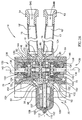
- Apparatus 10 includes a container 12 for containing a supply of a sterile liquid, such as any suitable saline solution, such as a 0.9% sodium chloride solution suitable for irrigation, and a fluid delivery head 14.
- a sterile liquid such as any suitable saline solution, such as a 0.9% sodium chloride solution suitable for irrigation
- head 14 has a liquid entry port 16, a gas entry port 18, and fluid outlet apparatus 20, via which a gas and liquid mist outflow is provided, at near sonic velocity. It is this outflow which is used for cleansing. as described below.
- container 12 may be closed by means of a five-way distributor cap 22, which is fastened to the container as by means of a screw thread (not shown), or by a snap-type or other suitable coupling.
- distributor cap 22 has a gas inlet port 24, first and second gas outlet ports, respectively referenced 26 and 28 (Figs. 1 and 2B), a liquid inlet port 30, and a liquid outlet port 32.
- a first gas conduit 34 has an inlet end 36, which is preferably removably coupled, via an oxygen plug 38, to an oxygen outlet 40, together defining a connection such as the "Silberman 2000" oxygen connection, well known and found in many hospitals in Israel and worldwide, and which has associated therewith a central, high pressure oxygen supply.
- the oxygen supply has a generally steady, non-pulsating pressure head, of approximately 3 atm.
- First gas conduit 34 also has an outlet end 42 which is attached, via a suitable screw or snap coupling 44, to gas inlet port 24.
- a second gas conduit, referenced 46 has an inlet end 48 and an outlet end 50.
- Inlet end 48 is attached, via a coupling 52, similar to coupling 44, to first gas outlet port 26, and outlet end 50 is attached, via suitable coupling 54, also similar to coupling 44, to an entry port 18' of a secondary gas conduit 19, coupled to gas entry port 18 of delivery head 14, as shown in Fig. 3A.
- a liquid conduit 56 has an inlet end 58 which is attached, via a coupling 59, similar to coupling 44, to liquid outlet port 32 of distributor cap 22, and, further, has an outlet end 60 which is attached, as by a suitable coupling 62, also similar to coupling 44, to an entry port 16' of a secondary liquid conduit 17, coupled to liquid entry port 16 of delivery head 14, as shown in Fig. 3A.
- a further tube portion, referenced 66, (Figs. 1 and 2A) is attached to liquid inlet port 30 of distributor cap 22, and has a free end 68, extending towards the floor of container 12, and which defines a liquid inlet 70.
- distributor cap 22 is formed such that gas inlet port 24 is connected with first and second gas outlet ports 26 and 28, thereby to facilitate a flow of gas from first gas conduit 34 (Fig. 1), through cap 22, and into second gas conduit 46 (Fig. 1), while also facilitating a pressurized supply of gas into container 12, via second gas outlet port 28.
- Liquid inlet port 30 and liquid outlet port 32 are also connected to each other, as seen, although the gas and liquid flows through the distributor cap 22 are kept separate.
- Figs. 3A, 3B and 3C in which the fluid delivery head 14 (Fig. 3A) and portions of the valve mechanisms thereof (Figs. 3B and 3C) are shown in detail.
- delivery head 14 has a liquid entry port 16, a gas entry port 18, and fluid outlet apparatus 20, via which a gas and liquid mist outflow is provided, at near sonic velocity.
- Fluid delivery head 14 includes a valve assembly, referenced generally 79, which facilitates passage of liquid and gas, respectively, from liquid entry port 16 and gas entry port 18, to a gas and liquid combining nozzle member 108, described below.
- Valve construction 79 includes a body 80 which has formed, in a rear portion thereof, liquid entry port 16 and gas entry port 18.
- Body 80 further includes laterally positioned liquid and gas valve chambers, respectively referenced 82 and 84, and which are separated from each other, but which are connected with respective entry ports 16 and 18 via a first liquid supply bore 86 and a first gas supply bore 88.
- Valve chambers 82 and 84 are also connected, via respective second liquid supply bore 90 and second gas supply bore 92, to a front portion of body 80, referenced generally 94.
- Front body portion 94 has formed thereon an inner recessed portion 96, and an outer recessed portion 98, which surrounds inner recessed portion.
- Inner recessed portion 96 communicates with second liquid supply bore 90
- outer recessed portion communicates with second gas supply bore 92.
- An inner nozzle member 100 is seated within inner recessed portion 96 so as to be contiguous with second liquid supply bore 90, and terminates in a narrow bore front nozzle opening 102, through which a narrow jet of liquid is emitted.
- a cylindrical, gas-liquid combining member 108 is mounted within outer recessed portion 98 concentric with surrounding inner nozzle member 100.
- Combining member 108 has a front portion, indicated generally 110, which is formed so as to converge towards an opening 112, which, as seen, is generally coaxial with nozzle opening 102 of inner nozzle member 100.
- Combining member 108 is configured so as to cause a central conversion of the gas throughflow in head 14 towards the liquid jet emerging from front nozzle opening 102. Accordingly, as the liquid jet and the gas flow converge upon each other, they become combined into a single gas and liquid jet in the front portion 110 of combining member 108.
- Each of valve chambers 82 and 84 contains a valve mechanism, having a construction typically as described below. As these typical valve mechanisms are identical to each other, they are both indicated by reference numeral 120, and the components common to both valve mechanisms are indicated by similar reference numerals.
- Each valve mechanism 120 has a cylindrical seating member 122, in which is located an inner valve plate 124.
- valve plate 124 has a generally conical, outwardly tapering valve opening 126 in which is seated a conical valve element 128.
- Valve element 128 is maintained, in the absence of any opposing forces, in a retracted, sealed position within opening 126, as shown in Fig. 3C, by means of resilient tension means 130, such as a tension spring.
- Each thumb controlled lever 72 (Figs. 1 and 3A) has a transversely extending threaded bore 134 (Fig. 3A) formed therein.
- a screw element 136 extends through bore 134 and terminates in a thickened end portion 138.
- a nut member 140 is connected to end portion 138, and is arranged for free rotation relative thereto, about the longitudinal axis 142 of screw element 136.
- Nut member 140 is seated in a piston-type casing 144 which is arranged for axial movement along inward-facing tracks 146 formed in seating member 122.
- valve opening 126 is closed by valve element 128.
- Rotation of lever 72 in a predetermined direction is operative to cause an inward, linear translation of screw element 136.
- nut member 140 is free to rotate about axis 142, it does not sustain any rotational moment, and is merely depressed inward by screw element 136.
- This inward movement causes a corresponding inward movement of casing 144 along tracks 146, which acts on a rear extension 148 of valve element 128 so as to depress it inwards, as shown by arrows 149 in Fig. 3B, thereby to cause a partial opening of valve opening 126, and enabling a throughflow of gas or liquid.
- Valve plate 124 has a plurality of first radial bores 150 formed in a rear portion thereof, which communicate with the interior of valve seating member 122.
- Valve seating member 122 has one or more second radial bores 152, which communicate with an exterior recess 154.
- the recesses 154 and the second liquid and gas supply bores 90 and 92 are formed such that opening of valve openings 126 enables respective throughflows of liquid and gas along flow paths constituted by valve openings 126, first radial bores 150 of valve plate 124, second radial bores 152 of valve seating member 122, recesses 154, and either of the supply bores 90 or 92.
- the gas is pressurized, and is supplied at a steady pressure of 2-3 atm. While there may be a minimal head loss during flow through delivery head 14, the delivery head 14 is constructed so as to minimize such head loss, and so as to ensure that the fluid pressure remains in excess of 2 atm, until the point where the combined jet emerges through opening 112 of combining member 108, into the atmosphere.
- the wetting of the contaminants in this way namely, by microscopic droplets, cause a substantial increase in their aerodynamic resistance, such that the force of the bombardment by the combined fluid jet is able to separate them from the tissue surface and carry them away in the droplet stream.
- the increase in the aerodynamic resistance of the particles is facilitated by the wetting by droplets, on the one hand, and by the absence of a liquid stream on the tissue surface with a stable boundary layer, on the other hand. Accordingly, as none of the contaminant matter is protected by a stable boundary layer of a liquid stream, it is all exposed to removal by the gas-liquid droplet stream.
- FIG. 4 illustrates a fluid delivery head, referenced generally 200
- Fig. 5 illustrates in detail the nozzle 202 of the fluid delivery head 200, constructed in accordance with an alternative embodiment of the invention.
- Delivery head 200 is similar to delivery head 14, shown and described above in conjunction with Figs. 1 and 3A, and is thus not described again herein except with regard to differences between delivery head 200 and delivery head 14. Accordingly, components of delivery head 200 seen in either of Figs. 1 or 3A, and having counterpart components therein, are denoted in Fig. 5 by similar reference numerals but with the addition of a prime (') notation.
- delivery head 200 is characterized by having a nozzle, referenced generally 202, which incorporates in a unitary member a rear, gas-liquid combining portion 204, and a front, suction portion 206.
- Nozzle 202 generally has an hourglass configuration, such that rear portion 204 and front portion 206 taper towards a narrow waist or transition portion 208.
- Inner nozzle member 100' is formed so as to protrude slightly through transition portion 208 and has a corresponding, slightly narrowed waist portion 210 whose diameter increases, as seen, as it protrudes into suction portion 206.
- An accelerating liquid stream emerging through passing through nozzle opening 102' emerges into the supersonic gas stream, and, due to the sharp pressure drop experienced, substantially as described above in conjunction with Figs. 1-3C. atomizes into microscopic droplets which are then swept into the gas stream, so as to form a combined gas-liquid mist stream.
- the fluid delivery head 200 When the fluid delivery head 200 is held close to tissue 224 contaminated with various pollutant particles, at a distance of, for example, 3-8 mm, these particles are exposed to the described subatmospheric pressure obtaining in the nozzle cavity. In addition to the microscopic liquid droplet bombardment as described above in conjunction with Figs. 1-3C, therefore, the pollutant particles are also exposed to a suction force as the nozzle is brought close to the tissue being cleansed, which helps to loosen the particles from the tissue, prior to being carried away in the gas-liquid mist.
Landscapes
- Health & Medical Sciences (AREA)
- Life Sciences & Earth Sciences (AREA)
- Heart & Thoracic Surgery (AREA)
- Surgery (AREA)
- Engineering & Computer Science (AREA)
- Biomedical Technology (AREA)
- Animal Behavior & Ethology (AREA)
- General Health & Medical Sciences (AREA)
- Public Health (AREA)
- Veterinary Medicine (AREA)
- Anesthesiology (AREA)
- Medical Informatics (AREA)
- Molecular Biology (AREA)
- Hematology (AREA)
- Nuclear Medicine, Radiotherapy & Molecular Imaging (AREA)
- Pathology (AREA)
- Oral & Maxillofacial Surgery (AREA)
- Nozzles (AREA)
- Loading And Unloading Of Fuel Tanks Or Ships (AREA)
- Detergent Compositions (AREA)
- Materials For Medical Uses (AREA)
- Containers And Packaging Bodies Having A Special Means To Remove Contents (AREA)
- Infusion, Injection, And Reservoir Apparatuses (AREA)
- Apparatus Associated With Microorganisms And Enzymes (AREA)
- Endoscopes (AREA)
- Medicines Containing Material From Animals Or Micro-Organisms (AREA)
- Measurement And Recording Of Electrical Phenomena And Electrical Characteristics Of The Living Body (AREA)
- Micro-Organisms Or Cultivation Processes Thereof (AREA)
- Treatment Of Fiber Materials (AREA)
- Cleaning By Liquid Or Steam (AREA)
- Investigating Or Analysing Biological Materials (AREA)
Claims (7)
- Vorrichtung (10) zum Reinigen von lebendem Gewebe unter Einsatz von Flüssigkeit und Gas als Arbeitsfluide, mit:wobei die Fluidauslasseinrichtung (20) ein Düsenelement (108,202) zum Aufnehmen der Gas- und Flüssigkeitsströme und zum Vereinigen dieser Ströme zu einem Gas-Flüssigkeits-Ausfluss, der die Vorrichtung (10) in Form eines sterilen Flüssigkeitsnebels in einem Hochgeschwindigkeits-Gasstrom durch den Fluidausslass (20) verlässt.einem Behälter (12) für eine sterile Flüssigkeit,einem Fluidzuführkopf (14,200) mit einem Flüssigkeitseintrittsport (16) und einem Gaseintrittsport (18), einer Fluideuslasseinrichtung (20) und einer Ventileinrichtung (79) zwischen den Eintrittsports (16,18) und der Fluidauslasseinrichtung (20) zum selektierbaren Strömentassen entweder der Flüssigkeit oder des Gases von den Eintrittsports (16,18) zu der Fluidauslasseinrichtung (20);einer Flüssigkeitsleitungseinrichtung (56) zwischen einem Flüssigkeitseinlass (58) in dem Behälter (12) und einem Flüssigkeitsauslass (60), der mit dem Flüssigkeitseintrittsport (16) des Zuführkopfs (14,200) verbunden ist;einer Gasleitungseinrichtung (34) zwischen einem Gaseinlass (36) und einem Gasauslass (42), wobei der Gaseinlass (36) mit einer Druckgasquelle verbindbar ist und der Gasauslass (42) mit dem Gaseintrittsport (18) des Zuführkopfs (14,200) verbunden ist, und wobei die Gasleitungseinrichtung (34) über einen Auslassport (26) mit dem Behälter (12) verbunden ist; undeiner Einrichtung zum selektierbaren Inkontaktbringen der Quelle steriler Flüssigkeit mit einem Druckgasstrom, der von dem Gaseinlass (36) zu dem Gasauslass (42) und in den Gaseintrittsport (18) des Fluidzuführkopfs (14, 200) strömt, wobei die sterile Flüssigkeit durch die Flüssigkeitsleitungseinrichtung (56) von dem Einlass (58) zu dem Auslass (60) und in den Flüssigkeitseintrittsport (16) des Fluidzuführkopfs . (14,200) gepumpt wird,
- Vorrichtung nach Anspruch 1, bei der der Gasstrom mit einem Druck einer ersten Größe aus der Ventileinrichtung (79) heraus und in das Gas-Flüssigkeits-Vereinigungselement (108,202) hinein strömt und die Vereinigungseinrichtung (108,202) einen Druckabfall in dem hindurch strömenden Gasstrom bewirkt, so dass der Druck des Gas-Flüssigkeits-Ausflusses hinter dem Fluidauslass (20) eine zweite Größe hat, wobei die erste Größe mindestens das Zweifache der zweiten Größe beträgt, um eine Schockwelle in dem Gas-Flüssigkeits-Strom hinter dem Fluidauslass (20) zu erzeugen und ein Zerstäuben des Flüssigkeitsanteils des Ausflusses in mikroskopische Tröpfchen zu bewirken, wodurch ein Nebel in dem Gasanteil des Ausflusses gebildet wird.
- Vorrichtung nach Anspruch 2, bei der der Gas-Flüssigkeits-Ausfluss hinter dem Fluidauslass (20) nahezu Schallgeschwindigkeit hat.
- Vorrichtung nach Anspruch 1, bei der der Gaseinlass (36) der Gasleitungseinrichtung (34) zum Verbinden mit einer unter Druck stehenden Sauerstoffquelle vorgesehen ist und der Ausfluss ein Ausfluss eines sterilen Flüssigkeitsnebels in einem Hochgeschwindigkeits-Sauerstoffstrom ist.
- Vorrichtung nach Anspruch 2, bei der die Fluidauslasseinrichtung (20) ferner eine Einrichtung (206) zum Aufbringen einer Saugkraft auf das zu reinigende Gewebe aufweist.
- Vorrichtung nach Anspruch 2, bei der die Fluidauslasseinrichtung (20) ferner mit einem innen liegenden Düsenelement (100') zum Erzeugen eines Ausflusses einer sterilen Flüssigkeit versehen ist und das Düsenelement (202) aufweist:wobei der Durchgang derart ausgebildet ist, dass er sich in Richtung des vorderen Teils (206) der Düse (202) in zunehmendem Maße derart verengt, dass der durch den Durchgang strömende Gasstrom mindestens auf Schallgeschwindigkeit beschleunigt wird,einen hinteren Teil (204), der derart ausgebildet ist, dass er auf das innen liegende Düsenelement (100') passt und der derart angeordnet ist, dass er auf das innen liegende Düsenelement (100') passt, um dazwischen einen Durchgang für den Gasstrom zu bilden;einen eingeschnürten Teil (208), der durch eine nach vorn gerichtete Verjüngung des hinteren Teils (204) gebildet ist;einen vorderen Teil (206), der eine Öffnung bildet und sich nach hinten in Richtung des eingeschnürten Teils (208) verjüngt,
und wobei sich der vordere Teil (206) in Richtung der darin ausgebildeten Öffnung erweitert, so dass sich der beschleunigte Gasstrom ausdehnt und somit einen Druckabfall auf einen subatmosphärischen Druck erfährt, so dass, wenn die Düsenöffnung nahe an das durch Schmutzpartikel verschmutzte Gewebe (224) heran gebracht ist, die Partikel dem subatmosphärischen Druck ausgesetzt sind, um dadurch von dem Gewebe (224) gelöst zu werden. - Vorrichtung nach Anspruch 1, bei der der Zuführkopf (14,200) derart ausgebildet ist, dass er bei der Benutzung mit einer Hand gehalten wird.
Applications Claiming Priority (5)
| Application Number | Priority Date | Filing Date | Title |
|---|---|---|---|
| IL11880196A IL118801A (en) | 1996-07-05 | 1996-07-05 | Apparatus and method for cleansing tissue |
| IL11880196 | 1996-07-05 | ||
| IL12002197 | 1997-01-16 | ||
| IL12002197A IL120021A0 (en) | 1997-01-16 | 1997-01-16 | Apparatus and method for cleansing tissue |
| PCT/IL1997/000027 WO1998001181A1 (en) | 1996-07-05 | 1997-01-22 | Apparatus and method for cleansing tissue |
Publications (3)
| Publication Number | Publication Date |
|---|---|
| EP0917481A1 EP0917481A1 (de) | 1999-05-26 |
| EP0917481A4 EP0917481A4 (de) | 2000-04-19 |
| EP0917481B1 true EP0917481B1 (de) | 2004-05-19 |
Family
ID=26323280
Family Applications (1)
| Application Number | Title | Priority Date | Filing Date |
|---|---|---|---|
| EP97900411A Expired - Lifetime EP0917481B1 (de) | 1996-07-05 | 1997-01-22 | Gerät und verfahren zur reinigung von gewebe |
Country Status (11)
| Country | Link |
|---|---|
| US (1) | US6283936B1 (de) |
| EP (1) | EP0917481B1 (de) |
| JP (1) | JP3794710B2 (de) |
| CN (1) | CN1150039C (de) |
| AT (1) | ATE267030T1 (de) |
| AU (1) | AU714415B2 (de) |
| BR (1) | BR9710210A (de) |
| DE (1) | DE69729199T2 (de) |
| NO (1) | NO318849B1 (de) |
| TR (1) | TR199802715T2 (de) |
| WO (1) | WO1998001181A1 (de) |
Families Citing this family (20)
| Publication number | Priority date | Publication date | Assignee | Title |
|---|---|---|---|---|
| IL122016A (en) * | 1997-10-22 | 2001-09-13 | Tav Tech Ltd | Apparatus for dermal abrasion |
| DE102004045502A1 (de) | 2004-09-20 | 2006-04-06 | Karl Storz Gmbh & Co. Kg | Spreizbares medizinisches Instrument für endoskopische Eingriffe |
| DK2230934T3 (da) | 2007-12-14 | 2012-11-26 | Aerodesigns Inc | Afgivelse af aerosoliserbare næringsmiddelprodukter |
| BR112013008859A2 (pt) * | 2010-10-11 | 2019-09-24 | Advanced Tech Materials Inc | sistema com base em revestimento, revestimento, e, métodos para dispensar os conteúdos de um sistema com base em revestimento, e para distribuir um material a um processo |
| WO2012052963A1 (en) | 2010-10-22 | 2012-04-26 | Medjet Ltd. | Endoscopic method and device |
| CN102785848A (zh) * | 2011-05-14 | 2012-11-21 | 长兴(广州)精细涂料有限公司 | 一种气动式油抽装置 |
| DE102012013464A1 (de) * | 2012-05-07 | 2013-11-07 | Heraeus Medical Gmbh | Lavage-System mit Düse |
| WO2013190537A1 (en) * | 2012-06-18 | 2013-12-27 | Michael Tavger | Method and system for delivering solution into the pores of recipient human skin |
| US9498089B2 (en) * | 2012-11-01 | 2016-11-22 | Conopco, Inc. | Sustainable mini shower |
| EP2777818A1 (de) * | 2013-03-15 | 2014-09-17 | Max-Planck-Gesellschaft zur Förderung der Wissenschaften e.V. | Verfahren und Vorrichtung zur Herstellung eines intermittierenden Flüssigkeitsstrahls |
| CN103550058B (zh) * | 2013-11-21 | 2015-08-19 | 江门大诚医疗器械有限公司 | 一种加氧清创器 |
| CN104525397B (zh) * | 2014-12-25 | 2023-05-30 | 重庆新派工业设计有限公司 | 可清洗型喷嘴 |
| WO2017117313A2 (en) | 2015-12-29 | 2017-07-06 | CEEK Enterprises | Sleeve for speculum and use thereof |
| US11918549B2 (en) | 2017-08-25 | 2024-03-05 | AZ Solutions LLC | System and method for wound treatment and irrigation |
| US10960129B2 (en) | 2017-08-25 | 2021-03-30 | AZ Solutions LLC | System and method for patient skin treatment and irrigation |
| WO2019040939A1 (en) | 2017-08-25 | 2019-02-28 | AZ Solutions LLC | SYSTEM AND METHOD FOR WOUND TREATMENT AND IRRIGATION |
| FR3082711A1 (fr) | 2018-06-26 | 2019-12-27 | L'oreal | Systeme d’injection sans aiguille |
| CN111150501A (zh) * | 2020-01-19 | 2020-05-15 | 华中科技大学同济医学院附属协和医院 | 一种具有喷药角度调节功能的消毒喷液设备及其控制方法 |
| FR3111272A1 (fr) | 2020-06-16 | 2021-12-17 | L'oreal | Dispositif d’injection sans aiguille d’une composition photo-polymérisable |
| US12485280B1 (en) * | 2024-07-15 | 2025-12-02 | Tav-Tech Ltd | Unitary enhanced jet spray dermal treatment handpiece |
Family Cites Families (18)
| Publication number | Priority date | Publication date | Assignee | Title |
|---|---|---|---|---|
| FR1329086A (fr) * | 1962-04-28 | 1963-06-07 | Procédé et dispositif pour l'application par pression statique de produits à action biologique | |
| DE1816838C3 (de) * | 1968-01-12 | 1973-08-16 | Svenska Utvecklings Ab | Vorrichtung zum waschen von personen, insbesondere bettlaegerigen patienten |
| GB1162790A (en) * | 1968-07-19 | 1969-08-27 | Andre Passe | Atomizing Apparatus for the Treatment of Wounds |
| US3804299A (en) * | 1973-01-08 | 1974-04-16 | P Kain | Automatic shampoo mixing and dispensing system |
| JPS5047743A (de) * | 1973-08-15 | 1975-04-28 | ||
| US3882864A (en) * | 1973-08-17 | 1975-05-13 | George R Montgomery | Selectively operated pressurized liquid applicator for sink installation |
| US4156495A (en) * | 1974-06-24 | 1979-05-29 | Sandco Limited | Method for producing drops or portions of liquid and viscous materials and for producing pellets therefrom |
| US5022414A (en) * | 1979-12-13 | 1991-06-11 | Joseph J. Berke | Tissue separator method |
| DE3109064C2 (de) * | 1981-03-10 | 1983-02-24 | Klaus Dr. 8029 Sauerlach Söchting | Dosierverfahren und Vorrichtung zur steuerbaren Abgabe von Sauerstoff und Flüssigkeiten in biologisch genutzte Systeme |
| US4462394A (en) * | 1982-05-03 | 1984-07-31 | Howmedica, Inc. | Intramedullary canal seal for cement pressurization |
| US4496081A (en) * | 1983-07-08 | 1985-01-29 | Fomo Products, Inc. | Dispensing apparatus |
| US4583531A (en) * | 1984-03-02 | 1986-04-22 | Terry M. Mattchen | Hand-held pulsating jet lavage |
| US4784180A (en) * | 1987-02-24 | 1988-11-15 | Knebel & Rottger Gmbh & Co. | Sanitary mixing valve assembly |
| US5059187A (en) * | 1988-11-30 | 1991-10-22 | Dey Laboratories, Inc. | Method for the cleansing of wounds using an aerosol container having liquid wound cleansing solution |
| US5370274A (en) * | 1989-11-24 | 1994-12-06 | Ohmi; Tadahiro | Apparatus for cleaning a wafer surface |
| US5419310A (en) * | 1992-11-03 | 1995-05-30 | Vision Sciences, Inc. | Partially inflated protective endoscope sheath |
| US5387200A (en) * | 1994-01-10 | 1995-02-07 | Sun-Safe Technologies Limited Partnership | Portable applicator for applying skin protection fluids |
| US5554111A (en) * | 1995-03-16 | 1996-09-10 | Mayo Foundation For Medical Education & Research | Bone cleaning and drying system |
-
1997
- 1997-01-22 JP JP50500398A patent/JP3794710B2/ja not_active Expired - Lifetime
- 1997-01-22 AT AT97900411T patent/ATE267030T1/de not_active IP Right Cessation
- 1997-01-22 CN CNB971961514A patent/CN1150039C/zh not_active Expired - Fee Related
- 1997-01-22 TR TR1998/02715T patent/TR199802715T2/xx unknown
- 1997-01-22 US US09/194,044 patent/US6283936B1/en not_active Expired - Lifetime
- 1997-01-22 AU AU13975/97A patent/AU714415B2/en not_active Ceased
- 1997-01-22 DE DE69729199T patent/DE69729199T2/de not_active Expired - Lifetime
- 1997-01-22 BR BR9710210-5A patent/BR9710210A/pt not_active IP Right Cessation
- 1997-01-22 EP EP97900411A patent/EP0917481B1/de not_active Expired - Lifetime
- 1997-01-22 WO PCT/IL1997/000027 patent/WO1998001181A1/en not_active Ceased
-
1999
- 1999-01-04 NO NO19990026A patent/NO318849B1/no not_active IP Right Cessation
Also Published As
| Publication number | Publication date |
|---|---|
| JP3794710B2 (ja) | 2006-07-12 |
| WO1998001181A1 (en) | 1998-01-15 |
| CN1150039C (zh) | 2004-05-19 |
| AU714415B2 (en) | 2000-01-06 |
| CN1228030A (zh) | 1999-09-08 |
| BR9710210A (pt) | 2000-01-11 |
| NO990026D0 (no) | 1999-01-04 |
| EP0917481A4 (de) | 2000-04-19 |
| US6283936B1 (en) | 2001-09-04 |
| NO318849B1 (no) | 2005-05-18 |
| JP2001507948A (ja) | 2001-06-19 |
| AU1397597A (en) | 1998-02-02 |
| DE69729199T2 (de) | 2005-01-27 |
| EP0917481A1 (de) | 1999-05-26 |
| TR199802715T2 (xx) | 1999-11-22 |
| ATE267030T1 (de) | 2004-06-15 |
| NO990026L (no) | 1999-03-03 |
| DE69729199D1 (de) | 2004-06-24 |
Similar Documents
| Publication | Publication Date | Title |
|---|---|---|
| EP0917481B1 (de) | Gerät und verfahren zur reinigung von gewebe | |
| AU737653B2 (en) | Dermal abrasion | |
| US4676242A (en) | Laser knife | |
| JP4144444B2 (ja) | 内視鏡の送液装置 | |
| EP0485133B1 (de) | Atherektomie mittels eines asymmetrischen Wasserstrahlkatheters | |
| US5151084A (en) | Ultrasonic needle with sleeve that includes a baffle | |
| EP1904150B1 (de) | Hochgeschwindigkeits-flüssiggasnebel-gewebeabrasionsvorrichtung | |
| US6425535B1 (en) | Fluid supplying apparatus for endoscope | |
| JPS6141219B2 (de) | ||
| CA2259530C (en) | Apparatus for cleansing tissue | |
| JP2010057728A (ja) | 配管接続アダプタ | |
| IL118801A (en) | Apparatus and method for cleansing tissue | |
| US5090904A (en) | Autoclavable air polisher handpiece | |
| KR20170126824A (ko) | 핑거로 작동하는 석션과 이리게이션 투웨이 디바이스 | |
| JP3368701B2 (ja) | 液体供給装置 | |
| RU2173099C2 (ru) | Устройство и способ для очистки ткани | |
| WO2000027339A2 (en) | Apparatus and method for cleansing tissue | |
| MXPA00003759A (es) | Abrasion dermica | |
| JPS6241013B2 (de) | ||
| JPS6317445Y2 (de) | ||
| JPH0260625A (ja) | 内視鏡の送気送水装置 | |
| JP3267400B2 (ja) | 送気用コネクタを設けた内視鏡 | |
| HK40038556A (en) | Microbubble generation device | |
| JPH0582401U (ja) | 処置具 | |
| AU7179900A (en) | Water jet atherectomy |
Legal Events
| Date | Code | Title | Description |
|---|---|---|---|
| PUAI | Public reference made under article 153(3) epc to a published international application that has entered the european phase |
Free format text: ORIGINAL CODE: 0009012 |
|
| 17P | Request for examination filed |
Effective date: 19990121 |
|
| AK | Designated contracting states |
Kind code of ref document: A1 Designated state(s): AT BE CH DE DK ES FI FR GB GR IE IT LI LU MC NL PT SE |
|
| A4 | Supplementary search report drawn up and despatched |
Effective date: 20000302 |
|
| AK | Designated contracting states |
Kind code of ref document: A4 Designated state(s): AT BE CH DE DK ES FI FR GB GR IE IT LI LU MC NL PT SE |
|
| 17Q | First examination report despatched |
Effective date: 20021210 |
|
| GRAP | Despatch of communication of intention to grant a patent |
Free format text: ORIGINAL CODE: EPIDOSNIGR1 |
|
| GRAS | Grant fee paid |
Free format text: ORIGINAL CODE: EPIDOSNIGR3 |
|
| GRAA | (expected) grant |
Free format text: ORIGINAL CODE: 0009210 |
|
| RAP1 | Party data changed (applicant data changed or rights of an application transferred) |
Owner name: TAV-TECH LTD. |
|
| AK | Designated contracting states |
Kind code of ref document: B1 Designated state(s): AT BE CH DE DK ES FI FR GB GR IE IT LI LU MC NL PT SE |
|
| PG25 | Lapsed in a contracting state [announced via postgrant information from national office to epo] |
Ref country code: NL Free format text: LAPSE BECAUSE OF FAILURE TO SUBMIT A TRANSLATION OF THE DESCRIPTION OR TO PAY THE FEE WITHIN THE PRESCRIBED TIME-LIMIT Effective date: 20040519 Ref country code: FI Free format text: LAPSE BECAUSE OF FAILURE TO SUBMIT A TRANSLATION OF THE DESCRIPTION OR TO PAY THE FEE WITHIN THE PRESCRIBED TIME-LIMIT Effective date: 20040519 Ref country code: BE Free format text: LAPSE BECAUSE OF FAILURE TO SUBMIT A TRANSLATION OF THE DESCRIPTION OR TO PAY THE FEE WITHIN THE PRESCRIBED TIME-LIMIT Effective date: 20040519 Ref country code: AT Free format text: LAPSE BECAUSE OF FAILURE TO SUBMIT A TRANSLATION OF THE DESCRIPTION OR TO PAY THE FEE WITHIN THE PRESCRIBED TIME-LIMIT Effective date: 20040519 |
|
| REG | Reference to a national code |
Ref country code: GB Ref legal event code: FG4D |
|
| REG | Reference to a national code |
Ref country code: CH Ref legal event code: EP |
|
| REG | Reference to a national code |
Ref country code: IE Ref legal event code: FG4D |
|
| REF | Corresponds to: |
Ref document number: 69729199 Country of ref document: DE Date of ref document: 20040624 Kind code of ref document: P |
|
| PG25 | Lapsed in a contracting state [announced via postgrant information from national office to epo] |
Ref country code: SE Free format text: LAPSE BECAUSE OF FAILURE TO SUBMIT A TRANSLATION OF THE DESCRIPTION OR TO PAY THE FEE WITHIN THE PRESCRIBED TIME-LIMIT Effective date: 20040819 Ref country code: GR Free format text: LAPSE BECAUSE OF FAILURE TO SUBMIT A TRANSLATION OF THE DESCRIPTION OR TO PAY THE FEE WITHIN THE PRESCRIBED TIME-LIMIT Effective date: 20040819 Ref country code: DK Free format text: LAPSE BECAUSE OF FAILURE TO SUBMIT A TRANSLATION OF THE DESCRIPTION OR TO PAY THE FEE WITHIN THE PRESCRIBED TIME-LIMIT Effective date: 20040819 |
|
| PG25 | Lapsed in a contracting state [announced via postgrant information from national office to epo] |
Ref country code: ES Free format text: LAPSE BECAUSE OF FAILURE TO SUBMIT A TRANSLATION OF THE DESCRIPTION OR TO PAY THE FEE WITHIN THE PRESCRIBED TIME-LIMIT Effective date: 20040830 |
|
| REG | Reference to a national code |
Ref country code: CH Ref legal event code: NV Representative=s name: KATZAROV S.A. |
|
| NLV1 | Nl: lapsed or annulled due to failure to fulfill the requirements of art. 29p and 29m of the patents act | ||
| PG25 | Lapsed in a contracting state [announced via postgrant information from national office to epo] |
Ref country code: LU Free format text: LAPSE BECAUSE OF NON-PAYMENT OF DUE FEES Effective date: 20050122 |
|
| PG25 | Lapsed in a contracting state [announced via postgrant information from national office to epo] |
Ref country code: MC Free format text: LAPSE BECAUSE OF NON-PAYMENT OF DUE FEES Effective date: 20050131 |
|
| ET | Fr: translation filed | ||
| PLBE | No opposition filed within time limit |
Free format text: ORIGINAL CODE: 0009261 |
|
| STAA | Information on the status of an ep patent application or granted ep patent |
Free format text: STATUS: NO OPPOSITION FILED WITHIN TIME LIMIT |
|
| 26N | No opposition filed |
Effective date: 20050222 |
|
| PG25 | Lapsed in a contracting state [announced via postgrant information from national office to epo] |
Ref country code: PT Free format text: LAPSE BECAUSE OF NON-PAYMENT OF DUE FEES Effective date: 20041019 |
|
| PGFP | Annual fee paid to national office [announced via postgrant information from national office to epo] |
Ref country code: IE Payment date: 20110120 Year of fee payment: 15 |
|
| PGFP | Annual fee paid to national office [announced via postgrant information from national office to epo] |
Ref country code: IT Payment date: 20110125 Year of fee payment: 15 Ref country code: FR Payment date: 20110202 Year of fee payment: 15 Ref country code: CH Payment date: 20110222 Year of fee payment: 15 Ref country code: DE Payment date: 20110218 Year of fee payment: 15 |
|
| PGFP | Annual fee paid to national office [announced via postgrant information from national office to epo] |
Ref country code: GB Payment date: 20110217 Year of fee payment: 15 |
|
| REG | Reference to a national code |
Ref country code: CH Ref legal event code: PL |
|
| GBPC | Gb: european patent ceased through non-payment of renewal fee |
Effective date: 20120122 |
|
| REG | Reference to a national code |
Ref country code: FR Ref legal event code: ST Effective date: 20120928 |
|
| REG | Reference to a national code |
Ref country code: IE Ref legal event code: MM4A |
|
| PG25 | Lapsed in a contracting state [announced via postgrant information from national office to epo] |
Ref country code: LI Free format text: LAPSE BECAUSE OF NON-PAYMENT OF DUE FEES Effective date: 20120131 Ref country code: GB Free format text: LAPSE BECAUSE OF NON-PAYMENT OF DUE FEES Effective date: 20120122 Ref country code: DE Free format text: LAPSE BECAUSE OF NON-PAYMENT OF DUE FEES Effective date: 20120801 Ref country code: CH Free format text: LAPSE BECAUSE OF NON-PAYMENT OF DUE FEES Effective date: 20120131 |
|
| REG | Reference to a national code |
Ref country code: DE Ref legal event code: R119 Ref document number: 69729199 Country of ref document: DE Effective date: 20120801 |
|
| PG25 | Lapsed in a contracting state [announced via postgrant information from national office to epo] |
Ref country code: IT Free format text: LAPSE BECAUSE OF NON-PAYMENT OF DUE FEES Effective date: 20120122 |
|
| PG25 | Lapsed in a contracting state [announced via postgrant information from national office to epo] |
Ref country code: FR Free format text: LAPSE BECAUSE OF NON-PAYMENT OF DUE FEES Effective date: 20120131 |
|
| PG25 | Lapsed in a contracting state [announced via postgrant information from national office to epo] |
Ref country code: IE Free format text: LAPSE BECAUSE OF NON-PAYMENT OF DUE FEES Effective date: 20120122 |