EP0917274A1 - Elektromotor - Google Patents
Elektromotor Download PDFInfo
- Publication number
- EP0917274A1 EP0917274A1 EP98890330A EP98890330A EP0917274A1 EP 0917274 A1 EP0917274 A1 EP 0917274A1 EP 98890330 A EP98890330 A EP 98890330A EP 98890330 A EP98890330 A EP 98890330A EP 0917274 A1 EP0917274 A1 EP 0917274A1
- Authority
- EP
- European Patent Office
- Prior art keywords
- component
- motor according
- rotor shaft
- electric motor
- sleeve
- Prior art date
- Legal status (The legal status is an assumption and is not a legal conclusion. Google has not performed a legal analysis and makes no representation as to the accuracy of the status listed.)
- Granted
Links
- 238000009423 ventilation Methods 0.000 claims abstract description 11
- 230000015572 biosynthetic process Effects 0.000 description 2
- 230000000295 complement effect Effects 0.000 description 2
- 239000000428 dust Substances 0.000 description 1
- 238000002347 injection Methods 0.000 description 1
- 239000007924 injection Substances 0.000 description 1
- 230000035515 penetration Effects 0.000 description 1
- 238000007789 sealing Methods 0.000 description 1
Images

Classifications
-
- F—MECHANICAL ENGINEERING; LIGHTING; HEATING; WEAPONS; BLASTING
- F16—ENGINEERING ELEMENTS AND UNITS; GENERAL MEASURES FOR PRODUCING AND MAINTAINING EFFECTIVE FUNCTIONING OF MACHINES OR INSTALLATIONS; THERMAL INSULATION IN GENERAL
- F16C—SHAFTS; FLEXIBLE SHAFTS; ELEMENTS OR CRANKSHAFT MECHANISMS; ROTARY BODIES OTHER THAN GEARING ELEMENTS; BEARINGS
- F16C33/00—Parts of bearings; Special methods for making bearings or parts thereof
- F16C33/72—Sealings
- F16C33/76—Sealings of ball or roller bearings
- F16C33/80—Labyrinth sealings
-
- F—MECHANICAL ENGINEERING; LIGHTING; HEATING; WEAPONS; BLASTING
- F16—ENGINEERING ELEMENTS AND UNITS; GENERAL MEASURES FOR PRODUCING AND MAINTAINING EFFECTIVE FUNCTIONING OF MACHINES OR INSTALLATIONS; THERMAL INSULATION IN GENERAL
- F16C—SHAFTS; FLEXIBLE SHAFTS; ELEMENTS OR CRANKSHAFT MECHANISMS; ROTARY BODIES OTHER THAN GEARING ELEMENTS; BEARINGS
- F16C35/00—Rigid support of bearing units; Housings, e.g. caps, covers
- F16C35/04—Rigid support of bearing units; Housings, e.g. caps, covers in the case of ball or roller bearings
-
- F—MECHANICAL ENGINEERING; LIGHTING; HEATING; WEAPONS; BLASTING
- F16—ENGINEERING ELEMENTS AND UNITS; GENERAL MEASURES FOR PRODUCING AND MAINTAINING EFFECTIVE FUNCTIONING OF MACHINES OR INSTALLATIONS; THERMAL INSULATION IN GENERAL
- F16J—PISTONS; CYLINDERS; SEALINGS
- F16J15/00—Sealings
- F16J15/44—Free-space packings
- F16J15/447—Labyrinth packings
- F16J15/4476—Labyrinth packings with radial path
-
- H—ELECTRICITY
- H02—GENERATION; CONVERSION OR DISTRIBUTION OF ELECTRIC POWER
- H02K—DYNAMO-ELECTRIC MACHINES
- H02K11/00—Structural association of dynamo-electric machines with electric components or with devices for shielding, monitoring or protection
- H02K11/40—Structural association with grounding devices
-
- H—ELECTRICITY
- H02—GENERATION; CONVERSION OR DISTRIBUTION OF ELECTRIC POWER
- H02K—DYNAMO-ELECTRIC MACHINES
- H02K5/00—Casings; Enclosures; Supports
- H02K5/04—Casings or enclosures characterised by the shape, form or construction thereof
- H02K5/12—Casings or enclosures characterised by the shape, form or construction thereof specially adapted for operating in liquid or gas
- H02K5/124—Sealing of shafts
-
- F—MECHANICAL ENGINEERING; LIGHTING; HEATING; WEAPONS; BLASTING
- F16—ENGINEERING ELEMENTS AND UNITS; GENERAL MEASURES FOR PRODUCING AND MAINTAINING EFFECTIVE FUNCTIONING OF MACHINES OR INSTALLATIONS; THERMAL INSULATION IN GENERAL
- F16C—SHAFTS; FLEXIBLE SHAFTS; ELEMENTS OR CRANKSHAFT MECHANISMS; ROTARY BODIES OTHER THAN GEARING ELEMENTS; BEARINGS
- F16C2380/00—Electrical apparatus
- F16C2380/26—Dynamo-electric machines or combinations therewith, e.g. electro-motors and generators
-
- H—ELECTRICITY
- H02—GENERATION; CONVERSION OR DISTRIBUTION OF ELECTRIC POWER
- H02K—DYNAMO-ELECTRIC MACHINES
- H02K11/00—Structural association of dynamo-electric machines with electric components or with devices for shielding, monitoring or protection
Definitions
- the invention relates to an electric motor and has the object to provide an electric motor in which the Sealing between the rotor shaft and the end shields is improved.
- the inventive design of the electric motor is between the component sitting on the shaft, which is in contact with the Shaft rotates, and the end shields an improved seal of the Electric motor, especially against dust penetration.
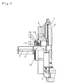
- An electric motor 1 has one shown only partially in FIG. 1 Stator housing 2, on which a screw connection 3 at both ends End shields 4 and 5 are attached. In the end shields 4 and 5 a rotor shaft 6 is mounted.
- Component 10 attached, one towards the electric motor 1 has pointing, sleeve-shaped approach 11.
- the one on the rotor shaft 6 seated component 10 also has an axis 7 of the rotor shaft 6 concentric, projecting ring rib pointing towards motor 1 12, which in a correspondingly oppositely shaped annular Groove 13 engages on the outside of the output plate 4.
- annular shoulder 14 On the outside of the annular rib 12 of the component 10 is an annular shoulder 14 provided that a ring step 15 in the end shield 4th opposite.
- annular formation 16 On the end shield 4 there is an outward-facing, annular formation 16 provided between the annular rib 12 and the sleeve 11 of the Component 10 engages. Between the outer end of the annular Formation 16 on the bearing plate 5 and the bottom of the groove between the The annular rib 12 and the sleeve 11 of the component 10 are a free space 17 intended. A fat deposit can be provided in this free space 17 become.
- the bearing plate 4 and the component 10 have the one on the rotor shaft 6 fixed, so with it rotating component 10 a radially after outwardly projecting flange-like projection 18, which the outside of the bearing plate 4 partially overlaps.
- the component 20 of the electric motor 1 also has one Sleeve 11, which bears against the rotor shaft 6 and at a distance from it Sleeve 11 is an annular rib 12, which is in an outwardly open, annular Groove 13 in the end shield 5 of the electric motor 1 on the ventilation side intervenes.
- the end shield 5 also has on the ventilation side an annular one within the outwardly open groove 13 Approach 16, which is in the groove between the annular rib 12 and the sleeve 11th of the component 20 engages so that a space 17 for a fat depot remains.
- the component 20 arranged on the ventilation side can, as in FIG. 2 shown simultaneously formed as a carrier for a fan wheel 21 be. It is preferred that the fan wheel 21 and that on the rotor shaft 6 component 20 placed on the ventilation side is formed in one piece are.
Landscapes
- Engineering & Computer Science (AREA)
- General Engineering & Computer Science (AREA)
- Mechanical Engineering (AREA)
- Power Engineering (AREA)
- Motor Or Generator Frames (AREA)
- Valve Device For Special Equipments (AREA)
- Transition And Organic Metals Composition Catalysts For Addition Polymerization (AREA)
- Glass Compositions (AREA)
Abstract
Description
Claims (10)
- Elektromotor (1) mit Lagerschilden (4 und 5), zur Lagerung der Rotorwelle (6) des Elektromotors (1), dadurch gekennzeichnet, daß auf der Rotorwelle (6) belüftungsseitig und/oder abtriebsseitig ein Bauteil (10, 20) befestigt ist und daß zwischen dem auf der Rotorwelle (6) festgelegten Bauteil (10, 20) und dem zugeordneten Lagerschild (4, 5) eine Labyrinthdichtung ausgebildet ist.
- Motor nach Anspruch 1, dadurch gekennzeichnet, daß der Bauteil (10, 20) über eine an ihm angeformte Hülse (11) auf der Rotorwelle (6) festgelegt ist.
- Motor nach Anspruch 2, dadurch gekennzeichnet, daß mit Abstand außerhalb der Hülse (11) des Bauteils (10, 20) eine Ringrippe (12) vorgesehen ist, und daß in die Nut zwischen Hülse (11) und Ringrippe (12) ein ringförmiger nach außen weisender Vorsprung (16) des Lagerschildes (4, 5) eingreift.
- Motor nach einem der Ansprüche 1 bis 3, dadurch gekennzeichnet, daß zwischen dem Bauteil (10, 20) und dem Lagerschild (4, 5) Raum (17) für die Aufnahme eines Fettdepots vorgesehen ist.
- Motor nach Anspruch 4, dadurch gekennzeichnet, daß der Raum (17) für die Aufnahme des Fettdepots zwischen dem freien Ende des nach außen weisenden Vorsprunges (16) des Lagerschildes (4, 5) und dem Boden der Nut zwischen der Hülse (11) und der Ringrippe (12) des Bauteils (10, 20) vorgesehen ist.
- Motor nach einem der Ansprüche 3 bis 5, dadurch gekennzeichnet, daß an der Ringrippe (12) des Bauteils (10, 20) radial außen eine ringförmige Schulter (14) vorgesehen ist, der eine ringförmige Stufe (15) am Lagerschild (4, 5) zugeordnet ist.
- Motor nach einem der Ansprüche 1 bis 6, dadurch gekennzeichnet, daß der Bauteil (10) eine radial abstehende, flanschförmige Anformung (18) aufweist, die das Lagerschild (4) außen teilweise übergreift.
- Motor nach einem der Ansprüche 1 bis 7, dadurch gekennzeichnet, daß der belüftungsseitig angeordnete, auf der Rotorwelle (6) festgelegte Bauteil (2) ein Lüfterrad (21) trägt.
- Motor nach Anspruch 8, dadurch gekennzeichnet, daß der Bauteil (20) und das Lüfterrad (21) einstückig ausgebildet sind.
- Motor nach einem der Ansprüche 1 bis 9, dadurch gekennzeichnet, daß der Bauteil (10, 20) aus Kunststoff besteht.
Applications Claiming Priority (4)
| Application Number | Priority Date | Filing Date | Title |
|---|---|---|---|
| AT195597 | 1997-11-18 | ||
| AT1955/97 | 1997-11-18 | ||
| AT42198 | 1998-03-10 | ||
| AT421/98 | 1998-03-10 |
Publications (2)
| Publication Number | Publication Date |
|---|---|
| EP0917274A1 true EP0917274A1 (de) | 1999-05-19 |
| EP0917274B1 EP0917274B1 (de) | 2007-01-03 |
Family
ID=25592692
Family Applications (1)
| Application Number | Title | Priority Date | Filing Date |
|---|---|---|---|
| EP98890330A Expired - Lifetime EP0917274B1 (de) | 1997-11-18 | 1998-11-10 | Elektromotor |
Country Status (4)
| Country | Link |
|---|---|
| EP (1) | EP0917274B1 (de) |
| AT (1) | ATE350800T1 (de) |
| DE (1) | DE59813866D1 (de) |
| ES (1) | ES2277379T3 (de) |
Cited By (4)
| Publication number | Priority date | Publication date | Assignee | Title |
|---|---|---|---|---|
| CN102022438A (zh) * | 2010-11-24 | 2011-04-20 | 山东华力电机集团股份有限公司 | 一种电机轴承迷宫密封装置 |
| US20110148230A1 (en) * | 2009-12-18 | 2011-06-23 | Ziehl-Abegg Ag | Electric Motor, Especially External Rotor Motor |
| WO2015058846A3 (de) * | 2013-10-22 | 2015-10-22 | Liebherr-Components Biberach Gmbh | Labyrinth-dichtung für drehstrommaschinen |
| US20160294244A1 (en) * | 2015-03-30 | 2016-10-06 | Siemens Aktiengesellschaft | Machine component of an electric machine and method for production thereof |
Citations (6)
| Publication number | Priority date | Publication date | Assignee | Title |
|---|---|---|---|---|
| US3552809A (en) * | 1969-01-29 | 1971-01-05 | Owens Mfg Inc | Lubricant and dust seal configuration |
| DE2362636A1 (de) * | 1973-12-17 | 1975-06-19 | Steag Ag | Getriebemotor |
| US4373759A (en) * | 1979-03-09 | 1983-02-15 | Skf (U.K.) Limited | Bearing assemblies for conveyor rollers fitted with end covers |
| FR2650130A1 (fr) * | 1989-07-19 | 1991-01-25 | Leroy Somer Moteurs | Joint d'etancheite, dispositif d'etancheite et machine dynamoelectrique ainsi equipes, et ensemble de composants s'y rapportant |
| EP0735644A2 (de) * | 1995-04-01 | 1996-10-02 | Bombas Electricas, S.A. (Boelsa) | Gehäuse eines elektrischen Motors |
| US5714817A (en) * | 1996-09-13 | 1998-02-03 | Synektron Corporation | Labyrinth seal system |
-
1998
- 1998-11-10 AT AT98890330T patent/ATE350800T1/de not_active IP Right Cessation
- 1998-11-10 ES ES98890330T patent/ES2277379T3/es not_active Expired - Lifetime
- 1998-11-10 DE DE59813866T patent/DE59813866D1/de not_active Expired - Fee Related
- 1998-11-10 EP EP98890330A patent/EP0917274B1/de not_active Expired - Lifetime
Patent Citations (6)
| Publication number | Priority date | Publication date | Assignee | Title |
|---|---|---|---|---|
| US3552809A (en) * | 1969-01-29 | 1971-01-05 | Owens Mfg Inc | Lubricant and dust seal configuration |
| DE2362636A1 (de) * | 1973-12-17 | 1975-06-19 | Steag Ag | Getriebemotor |
| US4373759A (en) * | 1979-03-09 | 1983-02-15 | Skf (U.K.) Limited | Bearing assemblies for conveyor rollers fitted with end covers |
| FR2650130A1 (fr) * | 1989-07-19 | 1991-01-25 | Leroy Somer Moteurs | Joint d'etancheite, dispositif d'etancheite et machine dynamoelectrique ainsi equipes, et ensemble de composants s'y rapportant |
| EP0735644A2 (de) * | 1995-04-01 | 1996-10-02 | Bombas Electricas, S.A. (Boelsa) | Gehäuse eines elektrischen Motors |
| US5714817A (en) * | 1996-09-13 | 1998-02-03 | Synektron Corporation | Labyrinth seal system |
Cited By (9)
| Publication number | Priority date | Publication date | Assignee | Title |
|---|---|---|---|---|
| US20110148230A1 (en) * | 2009-12-18 | 2011-06-23 | Ziehl-Abegg Ag | Electric Motor, Especially External Rotor Motor |
| US8531065B2 (en) * | 2009-12-18 | 2013-09-10 | Ziehl-Abegg Ag | Electric motor, especially external rotor motor |
| CN102022438A (zh) * | 2010-11-24 | 2011-04-20 | 山东华力电机集团股份有限公司 | 一种电机轴承迷宫密封装置 |
| WO2015058846A3 (de) * | 2013-10-22 | 2015-10-22 | Liebherr-Components Biberach Gmbh | Labyrinth-dichtung für drehstrommaschinen |
| CN105794091A (zh) * | 2013-10-22 | 2016-07-20 | 比伯拉赫利勃海尔零部件有限公司 | 三相电机的迷宫式密封件 |
| US10103597B2 (en) | 2013-10-22 | 2018-10-16 | Liebherr-Components Biberach Gmbh | Labyrinth seal for three-phase machines |
| AU2014339359B2 (en) * | 2013-10-22 | 2018-11-08 | Liebherr-Components Biberach Gmbh | Labyrinth seal for three-phase machines |
| US20160294244A1 (en) * | 2015-03-30 | 2016-10-06 | Siemens Aktiengesellschaft | Machine component of an electric machine and method for production thereof |
| US10727714B2 (en) * | 2015-03-30 | 2020-07-28 | Siemens Aktiengesellschaft | Machine component of an electric machine and method for production thereof |
Also Published As
| Publication number | Publication date |
|---|---|
| ATE350800T1 (de) | 2007-01-15 |
| EP0917274B1 (de) | 2007-01-03 |
| DE59813866D1 (de) | 2007-02-15 |
| ES2277379T3 (es) | 2007-07-01 |
Similar Documents
| Publication | Publication Date | Title |
|---|---|---|
| EP0698956B1 (de) | Anlauf- bzw. Abdeckscheibe für ein Lager auf einer Rotorwelle | |
| EP0170989A1 (de) | Getriebeanordnung, insbesondere Schneckengetriebeanordnung | |
| EP0500868B1 (de) | Antriebsvorrichtung, insbesondere für scheibenwischer an kraftfahrzeugen | |
| EP0549817A1 (de) | Verstellantrieb, insbesondere Kraftfahrzeug-Stellantrieb | |
| DE9108745U1 (de) | Elektromotor, insbesondere Kleinmotor für Kraftfahrzeug-Hilfsantriebe | |
| DE2603250A1 (de) | Dichtanordnung fuer ein axiallager | |
| DE69213116T2 (de) | Hermetisches Motorverdichtergehäuse | |
| DE2252085A1 (de) | Mehrreihen-kugellagerung | |
| DE3220614A1 (de) | Kleingeblaese | |
| DE19733566A1 (de) | Spindelmotor mit Hülse | |
| DE3434093A1 (de) | Getriebeanordnung, insbesondere schneckengetriebeanordnung | |
| EP0917274B1 (de) | Elektromotor | |
| EP1816729A2 (de) | Elektromotor | |
| EP1423630B1 (de) | Dichtungsanordnung, insbesondere zur abdichtung der spindelwelle einer spindel | |
| DE3131149C2 (de) | ||
| DE102014205095A1 (de) | Abdichtung einer Radlagereinheit | |
| EP0633645A1 (de) | Feuchtigkeitsdicht geschlossener Kommutatormotor zum Antrieb einer axial angeflanschten Hydraulikpumpe | |
| DE3532713A1 (de) | Anordnung zum befestigen ringfoermig geschlossener teile, insbesondere von luefterhauben, am gehaeuse eines elektromotors | |
| DE2551403C3 (de) | Kombinationsdichtung | |
| DE4123551A1 (de) | Ueberlappungsrotationspumpe | |
| DE1675100A1 (de) | Waelzlageranordnung | |
| DE2362636C3 (de) | Getriebemotor | |
| DE102017217029A1 (de) | Antriebsmodul eines Kraftfahrzeugs mit zwei um eine Antriebswelle abgedichteten Aufnahmeräumen | |
| DE2057693B2 (de) | Anordnung zur dichten Befestigung eines Motors in einer Öffnung eines Trägers, insbesondere eines Behälters oder Gefäßes | |
| DE3545886A1 (de) | Rotor fuer einen elektromotor |
Legal Events
| Date | Code | Title | Description |
|---|---|---|---|
| PUAI | Public reference made under article 153(3) epc to a published international application that has entered the european phase |
Free format text: ORIGINAL CODE: 0009012 |
|
| AK | Designated contracting states |
Kind code of ref document: A1 Designated state(s): AT BE CH DE ES FR GB IT LI LU NL SE |
|
| AX | Request for extension of the european patent |
Free format text: AL;LT;LV;MK;RO;SI |
|
| 17P | Request for examination filed |
Effective date: 19991105 |
|
| AKX | Designation fees paid |
Free format text: AT BE CH DE ES FR GB IT LI LU NL SE |
|
| 17Q | First examination report despatched |
Effective date: 20031230 |
|
| GRAP | Despatch of communication of intention to grant a patent |
Free format text: ORIGINAL CODE: EPIDOSNIGR1 |
|
| GRAS | Grant fee paid |
Free format text: ORIGINAL CODE: EPIDOSNIGR3 |
|
| GRAA | (expected) grant |
Free format text: ORIGINAL CODE: 0009210 |
|
| AK | Designated contracting states |
Kind code of ref document: B1 Designated state(s): AT BE CH DE ES FR GB IT LI LU NL SE |
|
| REG | Reference to a national code |
Ref country code: GB Ref legal event code: FG4D Free format text: NOT ENGLISH |
|
| REG | Reference to a national code |
Ref country code: SE Ref legal event code: TRGR |
|
| GBT | Gb: translation of ep patent filed (gb section 77(6)(a)/1977) |
Effective date: 20070103 |
|
| REF | Corresponds to: |
Ref document number: 59813866 Country of ref document: DE Date of ref document: 20070215 Kind code of ref document: P |
|
| ET | Fr: translation filed | ||
| REG | Reference to a national code |
Ref country code: ES Ref legal event code: FG2A Ref document number: 2277379 Country of ref document: ES Kind code of ref document: T3 |
|
| PLBE | No opposition filed within time limit |
Free format text: ORIGINAL CODE: 0009261 |
|
| STAA | Information on the status of an ep patent application or granted ep patent |
Free format text: STATUS: NO OPPOSITION FILED WITHIN TIME LIMIT |
|
| 26N | No opposition filed |
Effective date: 20071005 |
|
| PGFP | Annual fee paid to national office [announced via postgrant information from national office to epo] |
Ref country code: IT Payment date: 20071130 Year of fee payment: 10 |
|
| BERE | Be: lapsed |
Owner name: ATB AUSTRIA ANTRIEBSTECHNIK A.G. Effective date: 20071130 |
|
| PG25 | Lapsed in a contracting state [announced via postgrant information from national office to epo] |
Ref country code: LI Free format text: LAPSE BECAUSE OF NON-PAYMENT OF DUE FEES Effective date: 20071130 Ref country code: CH Free format text: LAPSE BECAUSE OF NON-PAYMENT OF DUE FEES Effective date: 20071130 |
|
| REG | Reference to a national code |
Ref country code: CH Ref legal event code: PL |
|
| PG25 | Lapsed in a contracting state [announced via postgrant information from national office to epo] |
Ref country code: BE Free format text: LAPSE BECAUSE OF NON-PAYMENT OF DUE FEES Effective date: 20071130 |
|
| PGFP | Annual fee paid to national office [announced via postgrant information from national office to epo] |
Ref country code: NL Payment date: 20081120 Year of fee payment: 11 Ref country code: DE Payment date: 20081103 Year of fee payment: 11 |
|
| PGFP | Annual fee paid to national office [announced via postgrant information from national office to epo] |
Ref country code: ES Payment date: 20081024 Year of fee payment: 11 Ref country code: AT Payment date: 20081125 Year of fee payment: 11 |
|
| PGFP | Annual fee paid to national office [announced via postgrant information from national office to epo] |
Ref country code: SE Payment date: 20081112 Year of fee payment: 11 |
|
| PGFP | Annual fee paid to national office [announced via postgrant information from national office to epo] |
Ref country code: FR Payment date: 20081022 Year of fee payment: 11 |
|
| PGFP | Annual fee paid to national office [announced via postgrant information from national office to epo] |
Ref country code: GB Payment date: 20081105 Year of fee payment: 11 |
|
| PG25 | Lapsed in a contracting state [announced via postgrant information from national office to epo] |
Ref country code: LU Free format text: LAPSE BECAUSE OF NON-PAYMENT OF DUE FEES Effective date: 20071110 Ref country code: IT Free format text: LAPSE BECAUSE OF NON-PAYMENT OF DUE FEES Effective date: 20081110 |
|
| REG | Reference to a national code |
Ref country code: NL Ref legal event code: V1 Effective date: 20100601 |
|
| EUG | Se: european patent has lapsed | ||
| GBPC | Gb: european patent ceased through non-payment of renewal fee |
Effective date: 20091110 |
|
| REG | Reference to a national code |
Ref country code: FR Ref legal event code: ST Effective date: 20100730 |
|
| PG25 | Lapsed in a contracting state [announced via postgrant information from national office to epo] |
Ref country code: AT Free format text: LAPSE BECAUSE OF NON-PAYMENT OF DUE FEES Effective date: 20091110 |
|
| PG25 | Lapsed in a contracting state [announced via postgrant information from national office to epo] |
Ref country code: NL Free format text: LAPSE BECAUSE OF NON-PAYMENT OF DUE FEES Effective date: 20100601 Ref country code: FR Free format text: LAPSE BECAUSE OF NON-PAYMENT OF DUE FEES Effective date: 20091130 |
|
| PG25 | Lapsed in a contracting state [announced via postgrant information from national office to epo] |
Ref country code: DE Free format text: LAPSE BECAUSE OF NON-PAYMENT OF DUE FEES Effective date: 20100601 |
|
| PG25 | Lapsed in a contracting state [announced via postgrant information from national office to epo] |
Ref country code: GB Free format text: LAPSE BECAUSE OF NON-PAYMENT OF DUE FEES Effective date: 20091110 |
|
| REG | Reference to a national code |
Ref country code: ES Ref legal event code: FD2A Effective date: 20110408 |
|
| PG25 | Lapsed in a contracting state [announced via postgrant information from national office to epo] |
Ref country code: SE Free format text: LAPSE BECAUSE OF NON-PAYMENT OF DUE FEES Effective date: 20091111 |
|
| PG25 | Lapsed in a contracting state [announced via postgrant information from national office to epo] |
Ref country code: ES Free format text: LAPSE BECAUSE OF NON-PAYMENT OF DUE FEES Effective date: 20110324 |
|
| PG25 | Lapsed in a contracting state [announced via postgrant information from national office to epo] |
Ref country code: ES Free format text: LAPSE BECAUSE OF NON-PAYMENT OF DUE FEES Effective date: 20091111 |