EP0917226A2 - Polymerelektrolytbrennstoffzelle - Google Patents
Polymerelektrolytbrennstoffzelle Download PDFInfo
- Publication number
- EP0917226A2 EP0917226A2 EP98121040A EP98121040A EP0917226A2 EP 0917226 A2 EP0917226 A2 EP 0917226A2 EP 98121040 A EP98121040 A EP 98121040A EP 98121040 A EP98121040 A EP 98121040A EP 0917226 A2 EP0917226 A2 EP 0917226A2
- Authority
- EP
- European Patent Office
- Prior art keywords
- polymer electrolyte
- gas diffusion
- diffusion layer
- fuel cell
- positive electrode
- Prior art date
- Legal status (The legal status is an assumption and is not a legal conclusion. Google has not performed a legal analysis and makes no representation as to the accuracy of the status listed.)
- Granted
Links
Images

Classifications
-
- H—ELECTRICITY
- H01—ELECTRIC ELEMENTS
- H01M—PROCESSES OR MEANS, e.g. BATTERIES, FOR THE DIRECT CONVERSION OF CHEMICAL ENERGY INTO ELECTRICAL ENERGY
- H01M4/00—Electrodes
- H01M4/86—Inert electrodes with catalytic activity, e.g. for fuel cells
- H01M4/88—Processes of manufacture
- H01M4/8803—Supports for the deposition of the catalytic active composition
- H01M4/8807—Gas diffusion layers
-
- H—ELECTRICITY
- H01—ELECTRIC ELEMENTS
- H01M—PROCESSES OR MEANS, e.g. BATTERIES, FOR THE DIRECT CONVERSION OF CHEMICAL ENERGY INTO ELECTRICAL ENERGY
- H01M4/00—Electrodes
- H01M4/86—Inert electrodes with catalytic activity, e.g. for fuel cells
- H01M4/90—Selection of catalytic material
- H01M4/92—Metals of platinum group
- H01M4/925—Metals of platinum group supported on carriers, e.g. powder carriers
- H01M4/926—Metals of platinum group supported on carriers, e.g. powder carriers on carbon or graphite
-
- H—ELECTRICITY
- H01—ELECTRIC ELEMENTS
- H01M—PROCESSES OR MEANS, e.g. BATTERIES, FOR THE DIRECT CONVERSION OF CHEMICAL ENERGY INTO ELECTRICAL ENERGY
- H01M4/00—Electrodes
- H01M4/86—Inert electrodes with catalytic activity, e.g. for fuel cells
- H01M4/96—Carbon-based electrodes
-
- H—ELECTRICITY
- H01—ELECTRIC ELEMENTS
- H01M—PROCESSES OR MEANS, e.g. BATTERIES, FOR THE DIRECT CONVERSION OF CHEMICAL ENERGY INTO ELECTRICAL ENERGY
- H01M8/00—Fuel cells; Manufacture thereof
- H01M8/10—Fuel cells with solid electrolytes
- H01M8/1004—Fuel cells with solid electrolytes characterised by membrane-electrode assemblies [MEA]
-
- H—ELECTRICITY
- H01—ELECTRIC ELEMENTS
- H01M—PROCESSES OR MEANS, e.g. BATTERIES, FOR THE DIRECT CONVERSION OF CHEMICAL ENERGY INTO ELECTRICAL ENERGY
- H01M2300/00—Electrolytes
- H01M2300/0017—Non-aqueous electrolytes
- H01M2300/0065—Solid electrolytes
- H01M2300/0082—Organic polymers
-
- H—ELECTRICITY
- H01—ELECTRIC ELEMENTS
- H01M—PROCESSES OR MEANS, e.g. BATTERIES, FOR THE DIRECT CONVERSION OF CHEMICAL ENERGY INTO ELECTRICAL ENERGY
- H01M8/00—Fuel cells; Manufacture thereof
- H01M8/04—Auxiliary arrangements, e.g. for control of pressure or for circulation of fluids
- H01M8/04291—Arrangements for managing water in solid electrolyte fuel cell systems
-
- Y—GENERAL TAGGING OF NEW TECHNOLOGICAL DEVELOPMENTS; GENERAL TAGGING OF CROSS-SECTIONAL TECHNOLOGIES SPANNING OVER SEVERAL SECTIONS OF THE IPC; TECHNICAL SUBJECTS COVERED BY FORMER USPC CROSS-REFERENCE ART COLLECTIONS [XRACs] AND DIGESTS
- Y02—TECHNOLOGIES OR APPLICATIONS FOR MITIGATION OR ADAPTATION AGAINST CLIMATE CHANGE
- Y02E—REDUCTION OF GREENHOUSE GAS [GHG] EMISSIONS, RELATED TO ENERGY GENERATION, TRANSMISSION OR DISTRIBUTION
- Y02E60/00—Enabling technologies; Technologies with a potential or indirect contribution to GHG emissions mitigation
- Y02E60/30—Hydrogen technology
- Y02E60/50—Fuel cells
Definitions
- the present invention relates to a polymer electrolyte fuel cell (hereinafter abbreviated as PEFC) which uses as the fuel such a reducing agent as pure hydrogen or modified hydrogen obtained from methanol or fossil fuels and uses as the reaction gas such an oxidizing agent as air or oxygen.
- PEFC polymer electrolyte fuel cell
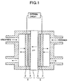
- a PEFC comprises a membrane/electrode assembly consisting essentially of a polymer electrolyte membrane and gas diffusion electrodes (hereinafter referred to as MEA), in which, as shown in Fig. 1, reactions represented by the formulas (1) and (2) take place respectively at the positive electrode 4 and the negative electrode 5.
- MEA polymer electrolyte membrane and gas diffusion electrodes
- the protons generated at the negative electrode move to the positive electrode via the polymer electrolyte membrane 1. Since a polymer electrolyte does not show a high ionic conductivity unless it is in a sufficiently moistened condition, generally the reaction gas needs to be always humidified by the use of a humidifier or the like in order to prevent the electrolyte from drying. On the other hand, the gas diffusion layer 2 of the electrode needs to have a high gas permeability in order that a high current density can be obtained. Therefore, to prevent the blockage of the gas diffusion path, excessive moisture must be discharged to the outside of the MEA.
- JP-A-6-295728 uses as the gas diffusion layer carbon paper formed essentially of carbon fiber made from polyacrylonitrile as the raw material and subjected to a water repellent treatment using fluororesin.
- the diffusion layer of the fuel electrode is provided with a hydrophobicity gradient such that the hydrophobicity is increasingly low toward the catalyst layer side 3 and the diffusion layer of the positive electrode is provided with a hydrophobicity gradient such that the hydrophobicity is increasingly high toward the catalyst layer side.
- the lowering of the moisture content of the polymer electrolyte of the fuel electrode side is prevented and the so-called flooding, which is a phenomenon wherein the catalyst layer is wetted by water formed at the positive electrode side and results in the blockage of the gas diffusion path.
- the polymer electrolyte membrane and the polymer electrolyte contained in the catalyst layer become dry and the movement of protons tends to take place with difficulty.
- the polymer electrolyte in the catalyst layer undergoes contraction to decrease the area of the electrolyte covering the platinum catalyst, that is, the reaction area, resulting in the increase of the internal resistance of the PEFC; thus, a good characteristic property cannot be obtained.
- the water-retaining property of the inside of the MEA is improved without hindering gas diffusion, whereby the polymer electrolyte can be sufficiently moistened by use of the water formed at the positive electrode and resultantly the operation of a PEFC using an unhumidified gas becomes possible.
- the object of the present invention is to provide a PEFC which can be operated by use of an unhumidified gas.
- a gas diffusion layer comprising an electroconductive porous material and 16-55% by weight of fluororesin added thereto is used for at least one of the positive and the negative electrodes, whereby the water-retaining property of the inside of the MEA can be improved without hindering gas diffusion and resultantly the polymer electrolyte can be moistened with the water formed at the positive electrode.
- an excellent water-retaining property of the inside of the MEA is attained without hindering gas diffusion and hence the polymer electrolyte can be sufficiently moistened with the water formed at the positive electrode, whereby a PEFC which can be operated by using an unhumidified gas can be provided.
- the aspect of the present invention described in claim 1 relates to a polymer electrolyte fuel cell which comprises a polymer electrolyte membrane and, arranged on the both sides thereof, a positive electrode and a negative electrode, the positive electrode and the negative electrode each comprising a catalyst layer and a gas diffusion layer, and is operated by feeding unhumidified air or oxygen to the positive electrode and feeding unhumidified hydrogen or reformed gas containing hydrogen to the negative electrode wherein the gas diffusion layer of at least one of the positive electrode and the negative electrode comprises an electroconductive porous material and 16-55% by weight of fluororesin added thereto.
- the diffusion of gas is not hindered and the inside of the MEA can attain an excellent water-retaining property, so that a PEFC can be provided wherein the polymer electrolyte can be sufficiently moistened with the water formed at the positive electrode and which can be operated by use of unhumidified gases.
- the percentage of the fluororesin added (sometimes referred to as “fluororesin addition percentage") is small the water repellency of the gas diffusion layer is low, so that the water formed and condensed in the catalyst layer of the positive electrode is apt to pass through the gas diffusion layer and be discharged to the outside of the MEA with ease. Consequently, the MEA becomes dry and the moisture content of the polymer electrolyte becomes low, resulting in a high internal resistance and a low voltage.
- the percentage of the fluororesin added is large, the water repellency of the gas diffusion layer is high and its porosity is low, so that the gas diffusion layer acts just like a cover for the MEA, and liquified water is apt to pass through the gas diffusion layer with difficulty.
- the gas permeability becomes low at the same time, the diffusion of the reaction gas becomes rate-determining and resultantly the voltage becomes low.
- the porosity of the gas diffusion layer subjected to water-repelling treatment is 45-75% by volume, a good effect is obtained in enhancing the water repellency of the gas diffusion layer without hindering gas diffusion and thereby enhancing the water-retaining property of the inside of the MEA, and a high performance PEFC can be provided.
- the porosity is more preferably 50-70% by volume.
- the specific volume of pores having a diameter of 17-90 ⁇ m in the gas diffusion layer subjected to water-repelling treatment is 0.45-1.25 cc/g, a good effect is obtained in enhancing the water repellency of the gas diffusion layer without hindering gas diffusion and thereby enhancing the water-retaining property of the inside of the MEA, and a high performance PEFC can be provided.
- the specific volume of pores having a diameter of 17-90 ⁇ m is more preferably 0.55-0.80 cc/g.
- an electrode which is prepared by the dropwise addition method comprising the step of dispersing carbon powder supporting a noble metal catalyst in an organic solvent to obtain a liquid dispersion, the step of mixing the liquid dispersion with an alcoholic solution of a polymer electrolyte to form a polymer electrolyte colloid and obtain at the same time a liquid mixture wherein the colloid is adsorbed to the carbon powder and the step of applying the liquid mixture on one side of the above-mentioned diffusion layer.
- Another example of the dropwise addition method comprises the step of preparing a colloid dispersion by mixing an organic solvent and an alcoholic solution of a solid polymer electrolyte to produce colloid, the step of preparing a liquid mixture by mixing the colloid dispersion and noble metal catalyst-supporting carbon powder to adsorb the colloid to the carbon powder and the step of applying the liquid mixture on one side of the above-mentioned diffusion layer.
- the former is preferable.
- Difference in the method of preparing a gas diffusion electrode leads to difference in the state of dispersion of the polymer electrolyte in the catalyst layer, which affects the characteristic property of the PEFC.
- the above-mentioned dropwise addition method is preferred.
- the polymer electrolyte is adsorbed to the platinum-supporting carbon powder thinly and in a highly dispersed state, so that the network of the polymer electrolyte in the catalyst layer grows reticulately all over the layer.
- such a state of the catalyst layer acts to return the generated water staying in the catalyst layer to the polymer electrolyte membrane with good efficiency; thus a PEFC with a higher performance can be provided.
- the present invention may also be a sub-combination of these described features.
- PEFCs obtained according to some embodiments of the present invention are described below.
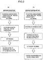
- An MEA is prepared as follows according to the method for preparing a gas diffusion electrode shown in Fig. 2(a) (hereinafter referred to as the impregnation method).
- Carbon powder carrying a platinum catalyst is mixed with carbon fine powder which has been water repelling-treated by addition of polytetrafluoroethylene (hereinafter abbreviated as PTFE).
- PTFE polytetrafluoroethylene
- the resulting powder mixture for catalyst is scattered on one side of carbon paper comprising carbon fiber made from polyacrylonitrile as the raw material to which 16-55% by weight of tetrafluoroethylene-hexafluoropropylene copolymer (hereinafter referred to as FEP) has been melt-bonded beforehand, and the resulting system is hot-pressed at 340-380°C and 5-20 kgf/cm 2 to obtain a gas diffusion electrode.
- FEP tetrafluoroethylene-hexafluoropropylene copolymer
- the addition of the polymer electrolyte to the gas diffusion electrode is conducted by using a method which comprises coating a solution mixture of isopropyl alcohol and a Nafion solution of a proportion of 0.05-1.5g of the latter per 2 ml of the former on the electrode while sucking the electrode from the carbon paper side by means of a pump, followed by drying.
- a polymer electrolyte membrane is held between two gas diffusion electrodes prepared as described above and the resulting system is hot-pressed by using a hot press at 120-170°C and 50 kgf/cm 2 .
- the MEA obtained through the above-mentioned steps does not hinder gas diffusion and is excellent in the water-retaining property of its inside.
- a PEFC can be provided in which the polymer electrolyte can be moistened with the water formed at the positive electrode and which can be operated by use of unhumidified gases.
- An MEA is prepared as follows according to the method for preparing a gas diffusion electrode shown in Fig. 2(b) (hereinafter referred to as the dropwise addition method).
- carbon powder supporting a platinum catalyst is mixed with carbon fine powder which has been water repelling-treated by addition of PTFE.
- the resulting powder mixture for catalyst is mixed with n-butyl acetate to obtain a liquid dispersion of platinum catalyst.
- To the liquid dispersion is added in drops, with stirring by means of a magnetic stirrer, an alcoholic solution of a polymer electrolyte, and then the resulting mixture is made into the form of paste by use of an ultrasonic disperser.
- the paste thus obtained is coated on one side of carbon paper comprising carbon fiber made from polyacrylonitrile as the raw material to which 16-55% by weight of FEP has been melt-bonded beforehand, and then dried to obtain a gas diffusion electrode.
- a polymer electrolyte membrane is held between two gas diffusion electrodes thus obtained and the whole is hot-pressed by using a hot press at 120-170°C and 50 kgf/cm 2 .
- the MEA obtained through the above-mentioned steps does not hinder gas diffusion. Furthermore, since the polymer electrolyte is adsorbed into the catalyst layer more thinly and in a more highly dispersed state than in the PEFC shown in Embodiment 1, this PEA is more excellent in the water-retaining property of the inside of the MEA. Consequently, a PEFC can be provided in which the polymer electrolyte can be moistened with the water formed at the positive electrode more efficiently and which can be operated by use of unhumidified gases.
- FEP fluororesin
- Each of the gas diffusion layers was prepared by immersing a carbon paper (mfd. by Toray Industries, Ltd.), used as the carbon paper comprising carbon fiber made from polyacrylonitrile as the raw material, in a FEP liquid dispersion obtained by diluting a FEP (ND-1, a Trade name, mfd. by Daikin Industries, Ltd.) with deionized water and then baking the resulting paper to melt-bond the FEP to the carbon paper.
- Gas diffusion layers A-F having a FEP addition amount ranging from 8 to 60% by weight as shown in Table 1 were prepared by controlling the degree of dilution of ND-1. FEP addition amount (wt%)
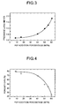
- Fig. 3 shows the relation between the FEP addition percentage and the pressure loss of the gas diffusion layer. The results obtained reveal that the pressure loss of the gas diffusion layer increases as the FEP addition percentage increases.
- gas diffusion layers A-F were determined for their porosity and pore size distribution by the mercury intrusion method.
- Fig. 4 shows the relation between the FEP addition amount and the porosity of the gas diffusion layer. The results obtained show that the porosity decreases as the FEP addition percentage increases, revealing that the pores are filled with FEP.
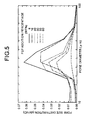
- Fig. 5 shows the pore size distribution of each of the gas diffusion layers A-F.
- Each of the curves show a large peak in the diameter range of 17-90 ⁇ m.
- the results obtained above reveal that, in the carbon paper used, the pores are predominantly in the range of diameter of 17-90 ⁇ m and the FEP is distributed among and in the pores of these diameters.
- Table 2 summarizes with the gas diffusion layers A-F, the FEP addition percentages, the porosities and the specific volumes of pores having a diameter of 17-90 ⁇ m.
- PEFCs were prepared as follows by using the gas diffusion layers A-F prepared in Example 1 and according to the impregnation method shown in Fig. 2(a).
- Carbon powder supporting 10-30% by weight of platinum catalyst and carbon fine powder which has been water repelling-treated by addition of 25-70% by weight of PTFE were mixed in a mixing ratio ranging from 8:2 to 5:5.
- Each of the resulting powder mixtures for catalyst layer was scattered on one side of the gas diffusion layer having the FEP addition percentage of 8-60% by weight obtained in Example 1, and the resulting system was hot-pressed at 340-380°C and 5-20 kgf/cm 2 .
- the addition of the polymer electrolyte to the electrode was conducted by a method which comprises coating a solution mixture of isopropyl alcohol and a "5% Nafion solution" (a trade name, mfd. by Aldrich Chemical Co., Ltd., USA) of a proportion of 0.05-1.5g of the latter per 2 ml of the former on the electrode while sucking the electrode from the carbon paper side by means of a pump, followed by drying. Then Nafion 112 (a polymer electrolyte membrane mfd.
- PEFCs were constructed by using the MEAs prepared above and designated as cells A-F.
- PEFCs were prepared as follows by using the gas diffusion layers A-F obtained in Example 1 and according to the dropwise addition method shown in Fig. 2(b).
- Carbon powder supporting 10-30% by weight of platinum catalyst and carbon fine powder which has been water repelling-treated by addition of 25-70% by weight of PTFE were mixed in a mixing ratio ranging from 8:2 to 5:5.
- the resulting powder mixture for catalyst layer was mixed with n-butyl acetate so as to give a weight ratio of platinum to n-butyl acetate of 1 to 120, to obtain a liquid dispersion of the platinum catalyst.
- To the liquid dispersion was added in drops, with stirring by means of a magnetic stirrer, an alcoholic solution of a polymer electrolyte until the amount ratio of platinum to polymer electrolyte reached 1:2, and the resulting mixture was made into the form of paste by using an ultrasonic disperser.
- the alcoholic solution of polymer electrolyte used was "5% Nafion solution" (a trade name, mfd. by Aldrich Chemical Co., Ltd., USA).
- the paste obtained above was coated on one side of the gas diffusion layer having a FEP addition percentage of 8-60% by weight obtained in Example 1 and then dried to obtain a gas diffusion electrode.
- a polymer electrolyte membrane, Nafion 112 (a trade name, mfd. by Du Pont de Nemours, E.I., Co., USA), was held between two electrodes obtained as described above and the resulting system was hot-pressed by using a hot press at 120-170°C and 50 kgf/cm 2 .
- the amounts of platinum and polymer electrolyte added were respectively 0.5 mg/cm 2 and 1.0 mg/cm 2 per apparent electrode area for both of the electrodes.
- PEFCs were constructed by using the MEAs prepared above and designated as cells a-f.
- the cells A-F prepared by the impregnation method in Example 2 and the cells a-f prepared by the dropwise addition method in Example 3 were each subjected to constant-current discharge at 0.2 A/cm 2 by feeding hydrogen gas to the negative electrode and air to the positive electrode both in the unhumidified state.
- Fig. 6 shows the relations between the percentage of FEP added to the gas diffusion layer and the voltages of cells A-F and cells a-f at a current value of 0.2 A/cm 2 .
- the voltage was 0.4 V or higher when the FEP addition percentage was 16-55% by weight, a high voltage being exhibited particularly at 40-50% by weight; when the FEP addition percentage was 8% by weight and 60% by weight, the cell voltage was very low, as low as 100 mV or lower.
- the voltage was 0.5 V or higher when the FEP addition percentage was 16-55% by weight, a high voltage being exhibited particularly at 40-50% by weight; when the FEP addition percentage was 8% by weight and 60% by weight, the cell voltage was very low, as low as 150 mV.
- the cell voltage showed similar behavior against the FEP addition percentage, but the cells prepared by the dropwise addition method showed 50-100 mV higher voltages at respective FEP addition percentages as compared with those by the impregnation method.
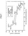
- Fig. 7 shows the relation between the percentage of FEP added to the gas diffusion layer and the internal resistance of the cell.
- the internal resistance of the cell decreased with the increase of the FEP addition percentage.
- the decrease of the resistance was particularly large when the FEP addition percentage increased from 8% by weight to 16% by weight.
- the internal resistance of the cells prepared by the impregnation method was higher than that of the cells prepared by the dropwise addition method over the whole range of FEP addition percentage.
- the gas permeability of the gas diffusion layer tends to lower, in other words the gas tends to diffuse with difficulty.
- the increase of the pressure loss is conceivably due to the decrease of porosity, that is, due to filling of FEP in the pores of the gas diffusion layer.
- the pores of the gas diffusion layer are predominantly of a diameter of 17-90 ⁇ m and the specific volume of the pores having a diameter of 17-90 ⁇ m is observed to decrease when the FEP addition percentage increases, it is considered that gases are supplied through the pores of the above-mentioned diameters and FEP is filled in the pores of said diameters.
- the water repellency is low due to the low FEP addition percentage, so that the water formed and condensed in the catalyst layer of the positive electrode passes through the gas diffusion layer and is discharged to the outside of the MEA with ease. It is considered that consequently the MEA becomes dry and the moisture content of the polymer electrolyte decreases to lower the ionic conductivity and increase the internal resistance of the PEFC. This increase of the internal resistance is considered as the cause of the lowering of voltage.
- the gas diffusion layer having a FEP addition percentage of 60% by weight has a high water repellency and low porosity, so that the layer acts just like a cover for the MEA and the liquified water passes through the gas diffusion layer only with difficulty.
- the water formed in the catalyst layer of the positive electrode and condensed is difficulty discharged to the outside of the MEA. It is considered that, consequently the water can be supplied via the polymer electrolyte in the positive electrode catalyst layer to the polymer electrolyte membrane and the polymer electrolyte in the fuel electrode catalyst layer and thus the MEA has a high water-retaining ability.
- a good balance between the water repellency of the diffusion layer and the gas permeability thereof is important for preparing a high performance PEFC which operates by unhumidified gas.
- Enhancing the water repellency of the gas diffusion layer without hindering gas diffusion and enhancing the water-retaining property of the inside of the MEA are effectively attained when the FEP addition percentage is 16-55% by weight, or when the porosity of the gas diffusion layer subjected to water repelling treatment is 45-75% by volume or when the specific volume of pores having a diameter of 17-90 ⁇ m of the gas diffusion layer subjected to water repelling treatment is 0.45-1.25 cc/g; the effect is particularly marked when the FEP addition percentage is 40-50% by weight, or when the porosity of the gas diffusion layer subjected to water repelling treatment is 50-70% by volume or when the specific volume of pores having a diameter of 17-90 ⁇ m in the gas diffusion layer subjected to water repelling treatment is 0.55-0.80 cc/g.
- a PEFC can be provided wherein the polymer electrolyte in the catalyst layer is adsorbed thinly and in a highly dispersed state and which exhibits more enhanced performance in the operation by unhumidified gas.
- FEP was used as the fluororesin in the present Examples, similar effects may also be obtained by using other fluororesins having water repellency, e.g., polytetrafluoroethylene, tetrafluoroethylene-perfluoroalkyl vinyl ether copolymer and tetrafluoroethyleneethylene copolymer.
- gas diffusion electrodes were prepared in the present Examples by preparing a paste comprising a platinum catalyst, polymer electrolyte and organic solvent and coating the paste on a carbon paper subjected to water repelling treatment, followed by drying, the present invention can be applied to the whole of the gas diffusion electrodes which comprise at least a noble metal catalyst and a polymer electrolyte irrespective of the method of preparation of the electrodes.
- carbon paper comprising carbon fiber made from polyacrylonitrile as the raw material was used as the electroconductive porous material, but the present invention can be applied to porous conductive materials in general, e.g., carbon cloth and carbon paper of cellulosic origin.
- perfluorocarbonsulfonic acid resin was used as the polymer electrolyte
- the present invention can be applied to such cation exchange resins in general as perfluorocarboncarboxylic acid resin, styrene-divinylbenzenesulfonic acid resin and styrene-butadienesulfonic acid resin.
- the water-retaining property of the inside of the MEA is improved without hindering gas diffusion and the polymer electrolyte is moistened by the water formed at the positive electrode, whereby an electrode for PEFC and a PEFC which are suited to operation by unhumidified gas can be obtained.
Applications Claiming Priority (3)
| Application Number | Priority Date | Filing Date | Title |
|---|---|---|---|
| JP30542597A JP3929146B2 (ja) | 1997-11-07 | 1997-11-07 | 固体高分子型燃料電池システム |
| JP30542597 | 1997-11-07 | ||
| JP305425/97 | 1997-11-07 |
Publications (3)
| Publication Number | Publication Date |
|---|---|
| EP0917226A2 true EP0917226A2 (de) | 1999-05-19 |
| EP0917226A3 EP0917226A3 (de) | 2005-06-22 |
| EP0917226B1 EP0917226B1 (de) | 2006-09-27 |
Family
ID=17944989
Family Applications (1)
| Application Number | Title | Priority Date | Filing Date |
|---|---|---|---|
| EP98121040A Expired - Lifetime EP0917226B1 (de) | 1997-11-07 | 1998-11-05 | Polymerelektrolytbrennstoffzelle |
Country Status (5)
| Country | Link |
|---|---|
| US (1) | US6194094B1 (de) |
| EP (1) | EP0917226B1 (de) |
| JP (1) | JP3929146B2 (de) |
| CA (1) | CA2253076C (de) |
| DE (1) | DE69835992T2 (de) |
Cited By (10)
| Publication number | Priority date | Publication date | Assignee | Title |
|---|---|---|---|---|
| WO2000019556A2 (de) * | 1998-09-30 | 2000-04-06 | Siemens Aktiengesellschaft | Reaktionswasserausbringung bei pem-brennstoffzellen |
| EP1176654A2 (de) * | 2000-07-25 | 2002-01-30 | Toyota Jidosha Kabushiki Kaisha | Brennstoffzelle |
| EP1306913A1 (de) * | 2000-08-04 | 2003-05-02 | Matsushita Electric Industrial Co., Ltd. | Polyelektrolyt-brennstoffzelle und herstellungsverfahren dafür |
| WO2003058743A2 (en) * | 2001-12-27 | 2003-07-17 | E.I. Du Pont De Nemours And Company | Gas diffusion backing for fuel cells |
| EP1533859A2 (de) * | 2003-11-06 | 2005-05-25 | Matsushita Electric Industrial Co., Ltd. | Diffusionsschicht für eine Brennstoffzelle |
| EP1538689A2 (de) * | 2003-12-04 | 2005-06-08 | Matsushita Electric Industrial Co., Ltd. | Gasdiffusionsschicht, Elektrode und Membranelektrodenanordnung für eine Brennstoffzelle und deren Herstellungsmethoden |
| EP1560284A1 (de) * | 2002-09-30 | 2005-08-03 | Asahi Glass Company, Limited | Elektrolytfilm, prozess zu seiner herstellung und brennstoffzelle des festpolymertyps |
| WO2006085428A1 (ja) * | 2005-02-10 | 2006-08-17 | Sony Corporation | 電気化学エネルギー生成装置及びこの装置の駆動方法 |
| WO2010050218A1 (ja) * | 2008-10-31 | 2010-05-06 | パナソニック株式会社 | 膜電極接合体及び燃料電池 |
| US8999603B2 (en) | 2008-10-31 | 2015-04-07 | Panasonic Corporation | Gas diffusion layer for fuel cell, manufacturing method therefor, membrane electrode assembly, and fuel cell |
Families Citing this family (18)
| Publication number | Priority date | Publication date | Assignee | Title |
|---|---|---|---|---|
| US6350539B1 (en) * | 1999-10-25 | 2002-02-26 | General Motors Corporation | Composite gas distribution structure for fuel cell |
| JP4470271B2 (ja) * | 2000-03-31 | 2010-06-02 | 株式会社エクォス・リサーチ | 燃料電池および燃料電池装置 |
| JP4714990B2 (ja) * | 2000-12-28 | 2011-07-06 | 株式会社豊田中央研究所 | 固体高分子型燃料電池 |
| JP3594533B2 (ja) * | 2000-05-30 | 2004-12-02 | 三洋電機株式会社 | 燃料電池 |
| JP2004536419A (ja) * | 2000-11-30 | 2004-12-02 | エムティーアイ・マイクロフューエル・セルズ・インコーポレイテッド | 燃料電池膜および一体化されたガス分離を有するシステム |
| JP2002343379A (ja) * | 2001-05-21 | 2002-11-29 | Aisin Seiki Co Ltd | 燃料電池、燃料電池用電極、燃料電池用電極の処理方法 |
| US7303835B2 (en) * | 2003-01-15 | 2007-12-04 | General Motors Corporation | Diffusion media, fuel cells, and fuel cell powered systems |
| JP4177697B2 (ja) * | 2003-04-09 | 2008-11-05 | 松下電器産業株式会社 | 高分子膜電極接合体および高分子電解質型燃料電池 |
| US20050026012A1 (en) * | 2003-07-28 | 2005-02-03 | O'hara Jeanette E. | Diffusion media tailored to account for variations in operating humidity and devices incorporating the same |
| US20080233436A1 (en) * | 2003-07-28 | 2008-09-25 | General Motors Corporation | Diffusion media tailored to account for variations in operating humidity and devices incorporating the same |
| US6967039B2 (en) * | 2003-07-28 | 2005-11-22 | General Motors Corporation | Untreated diffusion media with mesoporous layer and devices incorporating the same |
| US7332240B2 (en) * | 2003-07-28 | 2008-02-19 | General Motors Corporation | Spatially varying diffusion media and devices incorporating the same |
| US7157178B2 (en) * | 2003-11-24 | 2007-01-02 | General Motors Corporation | Proton exchange membrane fuel cell |
| WO2005086271A1 (en) * | 2004-03-05 | 2005-09-15 | Umicore Ag & Co Kg | Membrane electrode unit |
| JP4612569B2 (ja) | 2006-03-20 | 2011-01-12 | 本田技研工業株式会社 | 固体高分子型燃料電池用膜電極構造体 |
| JP2010177098A (ja) * | 2009-01-30 | 2010-08-12 | Toshiba Corp | ダイレクトメタノール型燃料電池、およびダイレクトメタノール型燃料電池用カソード |
| JP5843682B2 (ja) * | 2012-03-28 | 2016-01-13 | 本田技研工業株式会社 | 燃料電池の拡散層構造 |
| JP6356436B2 (ja) * | 2013-03-26 | 2018-07-11 | 本田技研工業株式会社 | 電解質膜・電極構造体 |
Citations (3)
| Publication number | Priority date | Publication date | Assignee | Title |
|---|---|---|---|---|
| EP0292431A2 (de) * | 1987-05-18 | 1988-11-23 | Eltech Systems Corporation | Gasdiffusionselektrode |
| JPH06295728A (ja) * | 1993-04-08 | 1994-10-21 | Matsushita Electric Ind Co Ltd | 固体高分子型燃料電池用電極およびそれを用いた燃料電池 |
| US5677074A (en) * | 1996-06-25 | 1997-10-14 | The Dais Corporation | Gas diffusion electrode |
Family Cites Families (6)
| Publication number | Priority date | Publication date | Assignee | Title |
|---|---|---|---|---|
| GB9213124D0 (en) * | 1992-06-20 | 1992-08-05 | Johnson Matthey Plc | High performance electrode |
| JP3422377B2 (ja) * | 1993-08-06 | 2003-06-30 | 松下電器産業株式会社 | 固体高分子型燃料電池の製造方法及びこれにより得られる固体高分子型燃料電池 |
| JP3331703B2 (ja) * | 1993-11-09 | 2002-10-07 | 株式会社豊田中央研究所 | 燃料電池 |
| JPH08115726A (ja) * | 1994-10-17 | 1996-05-07 | Tanaka Kikinzoku Kogyo Kk | 高分子固体電解質型電気化学セル用電極の製造方法 |
| JP3591123B2 (ja) * | 1996-03-08 | 2004-11-17 | トヨタ自動車株式会社 | 燃料電池および燃料電池用電極 |
| DE19611510A1 (de) * | 1996-03-23 | 1997-09-25 | Degussa | Gasdiffusionselektrode für Membranbrennstoffzellen und Verfahren zu ihrer Herstellung |
-
1997
- 1997-11-07 JP JP30542597A patent/JP3929146B2/ja not_active Expired - Fee Related
-
1998
- 1998-11-04 US US09/185,605 patent/US6194094B1/en not_active Expired - Lifetime
- 1998-11-05 CA CA002253076A patent/CA2253076C/en not_active Expired - Fee Related
- 1998-11-05 DE DE69835992T patent/DE69835992T2/de not_active Expired - Lifetime
- 1998-11-05 EP EP98121040A patent/EP0917226B1/de not_active Expired - Lifetime
Patent Citations (3)
| Publication number | Priority date | Publication date | Assignee | Title |
|---|---|---|---|---|
| EP0292431A2 (de) * | 1987-05-18 | 1988-11-23 | Eltech Systems Corporation | Gasdiffusionselektrode |
| JPH06295728A (ja) * | 1993-04-08 | 1994-10-21 | Matsushita Electric Ind Co Ltd | 固体高分子型燃料電池用電極およびそれを用いた燃料電池 |
| US5677074A (en) * | 1996-06-25 | 1997-10-14 | The Dais Corporation | Gas diffusion electrode |
Non-Patent Citations (1)
| Title |
|---|
| PATENT ABSTRACTS OF JAPAN vol. 1995, no. 01, 28 February 1995 (1995-02-28) -& JP 06 295728 A (MATSUSHITA ELECTRIC IND CO LTD), 21 October 1994 (1994-10-21) * |
Cited By (22)
| Publication number | Priority date | Publication date | Assignee | Title |
|---|---|---|---|---|
| WO2000019556A3 (de) * | 1998-09-30 | 2000-10-12 | Siemens Ag | Reaktionswasserausbringung bei pem-brennstoffzellen |
| US6576358B2 (en) | 1998-09-30 | 2003-06-10 | Siemens Aktiengesellschaft | Method of discharging reaction water in PEM fuel cells and fuel cell for carrying out the method |
| WO2000019556A2 (de) * | 1998-09-30 | 2000-04-06 | Siemens Aktiengesellschaft | Reaktionswasserausbringung bei pem-brennstoffzellen |
| EP1176654A2 (de) * | 2000-07-25 | 2002-01-30 | Toyota Jidosha Kabushiki Kaisha | Brennstoffzelle |
| EP1176654A3 (de) * | 2000-07-25 | 2002-08-14 | Toyota Jidosha Kabushiki Kaisha | Brennstoffzelle |
| US6933067B2 (en) | 2000-07-25 | 2005-08-23 | Toyota Jidosha Kabushiki Kaisha | Fuel cell |
| US7455703B2 (en) | 2000-08-04 | 2008-11-25 | Panasonic Corporation | Method for manufacturing polymer electrolyte fuel cell |
| EP1306913A1 (de) * | 2000-08-04 | 2003-05-02 | Matsushita Electric Industrial Co., Ltd. | Polyelektrolyt-brennstoffzelle und herstellungsverfahren dafür |
| EP1306913A4 (de) * | 2000-08-04 | 2006-03-22 | Matsushita Electric Ind Co Ltd | Polyelektrolyt-brennstoffzelle und herstellungsverfahren dafür |
| WO2003058743A2 (en) * | 2001-12-27 | 2003-07-17 | E.I. Du Pont De Nemours And Company | Gas diffusion backing for fuel cells |
| WO2003058743A3 (en) * | 2001-12-27 | 2004-09-30 | Du Pont | Gas diffusion backing for fuel cells |
| US6733915B2 (en) | 2001-12-27 | 2004-05-11 | E. I. Du Pont De Nemours And Company | Gas diffusion backing for fuel cells |
| US7749629B2 (en) | 2002-09-30 | 2010-07-06 | Asahi Glass Company, Limited | Electrolyte membrane, process for its production and polymer electrolyte fuel cell |
| EP1560284A1 (de) * | 2002-09-30 | 2005-08-03 | Asahi Glass Company, Limited | Elektrolytfilm, prozess zu seiner herstellung und brennstoffzelle des festpolymertyps |
| EP1560284A4 (de) * | 2002-09-30 | 2008-04-23 | Asahi Glass Co Ltd | Elektrolytfilm, prozess zu seiner herstellung und brennstoffzelle des festpolymertyps |
| EP1533859A3 (de) * | 2003-11-06 | 2007-06-27 | Matsushita Electric Industrial Co., Ltd. | Diffusionsschicht für eine Brennstoffzelle |
| EP1533859A2 (de) * | 2003-11-06 | 2005-05-25 | Matsushita Electric Industrial Co., Ltd. | Diffusionsschicht für eine Brennstoffzelle |
| EP1538689A2 (de) * | 2003-12-04 | 2005-06-08 | Matsushita Electric Industrial Co., Ltd. | Gasdiffusionsschicht, Elektrode und Membranelektrodenanordnung für eine Brennstoffzelle und deren Herstellungsmethoden |
| EP1538689A3 (de) * | 2003-12-04 | 2009-01-07 | Panasonic Corporation | Gasdiffusionsschicht, Elektrode und Membranelektrodenanordnung für eine Brennstoffzelle und deren Herstellungsmethoden |
| WO2006085428A1 (ja) * | 2005-02-10 | 2006-08-17 | Sony Corporation | 電気化学エネルギー生成装置及びこの装置の駆動方法 |
| WO2010050218A1 (ja) * | 2008-10-31 | 2010-05-06 | パナソニック株式会社 | 膜電極接合体及び燃料電池 |
| US8999603B2 (en) | 2008-10-31 | 2015-04-07 | Panasonic Corporation | Gas diffusion layer for fuel cell, manufacturing method therefor, membrane electrode assembly, and fuel cell |
Also Published As
| Publication number | Publication date |
|---|---|
| EP0917226A3 (de) | 2005-06-22 |
| CA2253076A1 (en) | 1999-05-07 |
| DE69835992D1 (de) | 2006-11-09 |
| CA2253076C (en) | 2002-07-09 |
| US6194094B1 (en) | 2001-02-27 |
| JP3929146B2 (ja) | 2007-06-13 |
| DE69835992T2 (de) | 2007-03-01 |
| JPH11144740A (ja) | 1999-05-28 |
| EP0917226B1 (de) | 2006-09-27 |
Similar Documents
| Publication | Publication Date | Title |
|---|---|---|
| US6194094B1 (en) | Polymer electrolyte fuel cell | |
| JP2842150B2 (ja) | 固体高分子型燃料電池 | |
| US5350643A (en) | Solid polymer electrolyte type fuel cell | |
| KR100513183B1 (ko) | 연료 전지 | |
| EP1045467B1 (de) | Geschichtete Kohlenstoffelektrode für elektrochemische Zellen | |
| JP4691914B2 (ja) | ガス拡散電極及び固体高分子電解質型燃料電池 | |
| JP4233208B2 (ja) | 燃料電池 | |
| US6187467B1 (en) | Ionomer impregnation of electrode substrates for improved fuel cell performance | |
| JP5118372B2 (ja) | 直接メタノール型燃料電池 | |
| US20100178583A1 (en) | Electrode composite material | |
| EP1519433A1 (de) | Diffusionselektrode für Brennstoffzellen | |
| WO2001017047A1 (fr) | Cellule electrochimique de type a electrolyte polymerique | |
| US20070202388A1 (en) | Membrane Electrode Unit | |
| US7094492B2 (en) | Electrode for polymer electrolyte fuel cell | |
| US20090136802A1 (en) | Solid polymer fuel cell | |
| US20090214918A1 (en) | Anode of direct methanol fuel cell and direct methanol fuel cell employing the same | |
| JPH0888007A (ja) | 固体高分子型燃料電池およびその電極 | |
| EP1133805B1 (de) | Imprägnierung mit ionomeren von elektrodensubstraten zur leistungsverbesserung von brennstoffzellen | |
| JP2011150893A (ja) | 固体高分子形燃料電池用ガス拡散層部材および固体高分子形燃料電池 | |
| US9312543B2 (en) | Fuel cell | |
| JP3813406B2 (ja) | 燃料電池 | |
| JPH10334922A (ja) | 固体高分子型燃料電池及び該固体高分子型燃料電池の製造方法 | |
| US11616247B2 (en) | Multi-interface membrane electrode assembly | |
| KR100907183B1 (ko) | 연료전지용 기체확산층, 막-전극 접합체 및 연료전지 | |
| US7147957B1 (en) | Electrode for fuel cell and manufacturing method therefor |
Legal Events
| Date | Code | Title | Description |
|---|---|---|---|
| PUAI | Public reference made under article 153(3) epc to a published international application that has entered the european phase |
Free format text: ORIGINAL CODE: 0009012 |
|
| 17P | Request for examination filed |
Effective date: 19981105 |
|
| AK | Designated contracting states |
Kind code of ref document: A2 Designated state(s): AT BE CH CY DE DK ES FI FR GB GR IE IT LI LU MC NL PT SE |
|
| AX | Request for extension of the european patent |
Free format text: AL;LT;LV;MK;RO;SI |
|
| PUAL | Search report despatched |
Free format text: ORIGINAL CODE: 0009013 |
|
| AK | Designated contracting states |
Kind code of ref document: A3 Designated state(s): AT BE CH CY DE DK ES FI FR GB GR IE IT LI LU MC NL PT SE |
|
| AX | Request for extension of the european patent |
Extension state: AL LT LV MK RO SI |
|
| AKX | Designation fees paid |
Designated state(s): DE FR GB |
|
| GRAP | Despatch of communication of intention to grant a patent |
Free format text: ORIGINAL CODE: EPIDOSNIGR1 |
|
| GRAS | Grant fee paid |
Free format text: ORIGINAL CODE: EPIDOSNIGR3 |
|
| GRAA | (expected) grant |
Free format text: ORIGINAL CODE: 0009210 |
|
| AK | Designated contracting states |
Kind code of ref document: B1 Designated state(s): DE FR GB |
|
| REG | Reference to a national code |
Ref country code: GB Ref legal event code: FG4D |
|
| REF | Corresponds to: |
Ref document number: 69835992 Country of ref document: DE Date of ref document: 20061109 Kind code of ref document: P |
|
| ET | Fr: translation filed | ||
| PLBE | No opposition filed within time limit |
Free format text: ORIGINAL CODE: 0009261 |
|
| STAA | Information on the status of an ep patent application or granted ep patent |
Free format text: STATUS: NO OPPOSITION FILED WITHIN TIME LIMIT |
|
| 26N | No opposition filed |
Effective date: 20070628 |
|
| PGFP | Annual fee paid to national office [announced via postgrant information from national office to epo] |
Ref country code: FR Payment date: 20121130 Year of fee payment: 15 Ref country code: DE Payment date: 20121031 Year of fee payment: 15 |
|
| PGFP | Annual fee paid to national office [announced via postgrant information from national office to epo] |
Ref country code: GB Payment date: 20121031 Year of fee payment: 15 |
|
| GBPC | Gb: european patent ceased through non-payment of renewal fee |
Effective date: 20131105 |
|
| REG | Reference to a national code |
Ref country code: FR Ref legal event code: ST Effective date: 20140731 |
|
| REG | Reference to a national code |
Ref country code: DE Ref legal event code: R119 Ref document number: 69835992 Country of ref document: DE Effective date: 20140603 |
|
| PG25 | Lapsed in a contracting state [announced via postgrant information from national office to epo] |
Ref country code: DE Free format text: LAPSE BECAUSE OF NON-PAYMENT OF DUE FEES Effective date: 20140603 |
|
| PG25 | Lapsed in a contracting state [announced via postgrant information from national office to epo] |
Ref country code: GB Free format text: LAPSE BECAUSE OF NON-PAYMENT OF DUE FEES Effective date: 20131105 Ref country code: FR Free format text: LAPSE BECAUSE OF NON-PAYMENT OF DUE FEES Effective date: 20131202 |