EP0917027B1 - Process cartridge and electrophotographic image forming apparatus - Google Patents
Process cartridge and electrophotographic image forming apparatus Download PDFInfo
- Publication number
- EP0917027B1 EP0917027B1 EP98309256A EP98309256A EP0917027B1 EP 0917027 B1 EP0917027 B1 EP 0917027B1 EP 98309256 A EP98309256 A EP 98309256A EP 98309256 A EP98309256 A EP 98309256A EP 0917027 B1 EP0917027 B1 EP 0917027B1
- Authority
- EP
- European Patent Office
- Prior art keywords
- cartridge
- process cartridge
- contact portion
- main body
- photosensitive member
- Prior art date
- Legal status (The legal status is an assumption and is not a legal conclusion. Google has not performed a legal analysis and makes no representation as to the accuracy of the status listed.)
- Expired - Lifetime
Links
- 238000000034 method Methods 0.000 title claims description 97
- 238000004140 cleaning Methods 0.000 claims description 18
- 239000000463 material Substances 0.000 claims description 5
- 229920003023 plastic Polymers 0.000 claims description 5
- 239000004033 plastic Substances 0.000 claims description 5
- 230000015572 biosynthetic process Effects 0.000 description 3
- KAKZBPTYRLMSJV-UHFFFAOYSA-N Butadiene Chemical compound C=CC=C KAKZBPTYRLMSJV-UHFFFAOYSA-N 0.000 description 2
- 238000003780 insertion Methods 0.000 description 2
- 230000037431 insertion Effects 0.000 description 2
- 230000003287 optical effect Effects 0.000 description 2
- -1 polyethylene Polymers 0.000 description 2
- NLHHRLWOUZZQLW-UHFFFAOYSA-N Acrylonitrile Chemical compound C=CC#N NLHHRLWOUZZQLW-UHFFFAOYSA-N 0.000 description 1
- 239000004698 Polyethylene Substances 0.000 description 1
- 239000004743 Polypropylene Substances 0.000 description 1
- PPBRXRYQALVLMV-UHFFFAOYSA-N Styrene Natural products C=CC1=CC=CC=C1 PPBRXRYQALVLMV-UHFFFAOYSA-N 0.000 description 1
- 229920000122 acrylonitrile butadiene styrene Polymers 0.000 description 1
- 229920001577 copolymer Polymers 0.000 description 1
- 238000005516 engineering process Methods 0.000 description 1
- 238000012423 maintenance Methods 0.000 description 1
- 229920000515 polycarbonate Polymers 0.000 description 1
- 239000004417 polycarbonate Substances 0.000 description 1
- 229920000573 polyethylene Polymers 0.000 description 1
- 229920001155 polypropylene Polymers 0.000 description 1
Images


Classifications
-
- G—PHYSICS
- G03—PHOTOGRAPHY; CINEMATOGRAPHY; ANALOGOUS TECHNIQUES USING WAVES OTHER THAN OPTICAL WAVES; ELECTROGRAPHY; HOLOGRAPHY
- G03G—ELECTROGRAPHY; ELECTROPHOTOGRAPHY; MAGNETOGRAPHY
- G03G21/00—Arrangements not provided for by groups G03G13/00 - G03G19/00, e.g. cleaning, elimination of residual charge
- G03G21/16—Mechanical means for facilitating the maintenance of the apparatus, e.g. modular arrangements
- G03G21/18—Mechanical means for facilitating the maintenance of the apparatus, e.g. modular arrangements using a processing cartridge, whereby the process cartridge comprises at least two image processing means in a single unit
- G03G21/1839—Means for handling the process cartridge in the apparatus body
- G03G21/1842—Means for handling the process cartridge in the apparatus body for guiding and mounting the process cartridge, positioning, alignment, locks
- G03G21/1853—Means for handling the process cartridge in the apparatus body for guiding and mounting the process cartridge, positioning, alignment, locks the process cartridge being mounted perpendicular to the axis of the photosensitive member
-
- G—PHYSICS
- G03—PHOTOGRAPHY; CINEMATOGRAPHY; ANALOGOUS TECHNIQUES USING WAVES OTHER THAN OPTICAL WAVES; ELECTROGRAPHY; HOLOGRAPHY
- G03G—ELECTROGRAPHY; ELECTROPHOTOGRAPHY; MAGNETOGRAPHY
- G03G2221/00—Processes not provided for by group G03G2215/00, e.g. cleaning or residual charge elimination
- G03G2221/16—Mechanical means for facilitating the maintenance of the apparatus, e.g. modular arrangements and complete machine concepts
- G03G2221/1672—Paper handling
Definitions
- the present invention relates to an electrophotographic image forming apparatus such as a laser beam printer or a copying apparatus, and a process cartridge for use in such electrophotographic image forming apparatus.
- the electrophotographic image forming apparatus based on the electrophotographic image forming process executes selective exposure according to image information on an electrophotographic photosensitive member uniformly charged with charging means to form a latent image. Then it develops such latent image with toner in developing means to form a toner image, and transfers the toner image formed on the electrophotographic photosensitive member onto a recording sheet by transfer means to execute image formation.
- the charging means, developing means or cleaning means with the electrophotographic photosensitive member as a process cartridge which is detachably mounted in the main body of the image forming apparatus.
- the image formation is achieved by conveying the recording sheet by paired rollers.
- the recording sheet is pinched and conveyed by a convey roller driven by a motor through gears and an idler roller rotated in pressure contact with such convey roller, and the image is formed on such recording sheet by image forming means.
- a guide member is provided in the conveying direction of the above-mentioned paired rollers, in order to achieve exact conveyance of the recording sheet.
- recording sheet conveying means there has been already known a guide member that can be retracted in case of sheet jamming, in order to facilitate removal of the jammed recording sheet.
- the present invention is to further extend the prior technology.
- JP-A-09106125 discloses an electrophotographic image forming apparatus for forming an image on a recording medium and on which a process cartridge is detachably mountable, comprising:
- US-A-5,245,394 discloses an electrophotographic image forming apparatus for forming an image on a recording medium and on which a process cartridge is detachably mountable, comprising:
- the present invention is characterised in that characterised in that characterised in that the photosensitive member is in the form of a drum and said cartridge contact portion is provided at an end of the photosensitive member in an axial direction thereof in such a manner as to protrude forward of said electrophotographic member in the direction of mounting of the process cartridge in the main body of said apparatus; the guide member will be prevented from moving to the retracted position by impinging on the process cartridge at a position that is spaced apart from the cartridge contact portion when said process cartridge is mounted in the main body of the apparatus; said cartridge contact portion and the position at which the guide member can impinge on the process cartridge are provided on one side and the other side respectively of the electrophotographic photosensitive member in a direction intersecting the longitudinal direction of the photosensitive member; and said cartridge contact portion is provided on a downstream side of the position in the mounting direction.
- the apparatus according to the invention has the advantage of improving the operability in mounting or detaching (removing) the process cartridge on or from the main body of the image forming apparatus.
- Another advantage of the present invention is that the apparatus is capable, even when the process cartridge is mounted without returning the guide member to the original position, of preventing the guide member from impinging on the electrophotographic photosensitive drum thereby preventing the electrophotographic photosensitive drum from being damaged.
- Still another advantage of the present invention is that if the guide member provided in the main body of the apparatus is in the aforementioned retracted position, in mounting the process cartridge on the main body of the apparatus, the guide member is shifted to the guide position.
- the invention provides a process cartridge adapted for use in a main body of an electrophotographic image forming apparatus for forming an image on a recording medium and on which the process cartridge is detachably mountable, comprising:
- a process cartridge used in a first embodiment and an electrophotographic image forming apparatus capable of mounting such process cartridge thereon At first reference is made to Figs. 3 to 5 for explaining the entire configuration of the process cartridge and the image forming apparatus capable of mounting the same, then to Figs. 2, 6A and 6B for explaining an upper transfer guide, and finally to Figs. 1, 6A, 6B and 9 for explaining the relationship between the shape of a frame member of the process cartridge and the upper transfer guide.
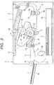
- a laser beam emitted from an optical system 1 and modulated according to the image information irradiates a drum-shaped electrophotographic photosensitive member (photosensitive drum) 7 to form a latent image thereon, which is then developed into a toner image.
- a recording sheet (recording medium) is picked up from a sheet cassette 3a by a pickup roller 3b and is conveyed, by conveying means composed of paired convey rollers 3c, an upper transfer guide 103 etc., to a nip portion between the photosensitive drum 7 and a transfer roller (transfer means) 4.
- the fixing means 5 is composed of a driving roller 5a and a fixing roller 5c incorporating a heater 5b, and applies heat and pressure to the passing recording sheet 2 thereby fixing the transferred toner image. Subsequently the recording sheet 2 is conveyed by paired discharge rollers 3e, 3f and is discharged to a discharge unit 6 through an inverting path.
- the image forming apparatus A also allows manual sheet feeding by a manual insertion tray 3g and a roller 3h.
- a process cartridge B is provided with an electrophotographic photosensitive member and at least a process means.
- process means includes charging means for charging the electrophotographic photosensitive member, developing means for developing the latent image formed on the electrophotographic photosensitive member, and cleaning means for removing the toner remaining on the electrophotographic photosensitive member.
- the process cartridge is for rotating the drum-shaped electrphotographic photosensitive member (hereinafter called “photosensitive drum”) 7, uniformly charging the surface thereof by voltage application to the charging roller 8a (charging means 8), exposing the photosensitive drum 7 to the information-bearing light beam from the optical system 1 thereby forming a latent image, and developing the latent image by developing means 10.
- photosensitive drum drum-shaped electrphotographic photosensitive member
- the developing means 10 is for feeding the toner in a toner container 10a by a toner feeding member 10b, rotating a developing roller 10d incorporating a fixed magnet 10c, forming a toner layer having a triboelectric charge caused by a developing blade 10e on the surface of the developing roller 10d, and transferring the toner to the photosensitive drum 7 according to the latent image thereby forming a visible toner image.
- the toner remaining on the photosensitive drum 7 is eliminated by the cleaning means 11 in which the remaining toner is scraped off by a cleaning blade 11a, then scooped up by a scooping sheet 11b, and is collected in a used toner container 11c.
- a developing unit is formed by fusing the toner container 12a with a developing frame 12b supporting developing members such as the developing roller 10d, and is housed in a cartridge frame constructed by combining a cleaning frame 12c with a cleaning unit supporting the photosensitive drum 7, the cleaning means 11 etc.
- the above-mentioned components such as the photosensitive drum 7 are formed as a cartridge, which is detachably mounted on cartridge mounting means provided in a main body 13 of the apparatus.
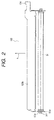
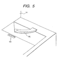
- cartridge mounting means consisting of cartridge mounting guides 15 (15L, 15R) formed as arc-shaped grooves on both lateral faces of a cartridge mounting space (Fig. 5 showing one lateral face only) and constituting guides for inserting the process cartridge B.
- the cartridge B can be mounted on the image forming apparatus A by fitting pins 16 and positioning members (not shown) protruding on both ends in the longitudinal direction of the cartridge frame, positioning the pins 16 at the end of the guides 15 and closing the cover 14.
- the conveying path for the recording sheet 2, from the sheet cassette 3a to the nip between the photosensitive drum 7 and the transfer roller 4 is composed of an inverting guide 3d for inverting the recording sheet 2 fed from the sheet cassette 3a by the pickup roller 3b, a conveying path formed by a fixed upper guide 3i and a fixed lower guide 3j positioned respectively corresponding to the manual insertion roller 3h and the inverting guide 3d, paired convey rollers 3c provided at the exit side of the conveying path, a movable upper transfer guide 103 for guiding the recording sheet 2 from the paired convey rollers 3c to the nip between the photosensitive drum 7 and the transfer roller 4, and a fixed lower transfer guide 3k.
- the upper transfer guide 103 is rotatably mounted on the shaft 3cl of the upper roller of the paired convey rollers 3c.
- the operator detaches the process cartridge B. It is thus rendered possible to easily remove the jammed recording sheet 2 by manually lifting upwards the upper transfer guide 103.
- the convey roller 3c is made longer than the width of the recording sheet 2 perpendicular to the conveying direction (a) thereof, and on each of the shafts 3cl protruding on both ends of the roller there are articulated a base portion of an arm 103a of the upper transfer guide 103 integral with a guide portion 103b, and a bent 103c radially distant from the articulated portion impinges on a stopper (not shown) whereby the upper transfer guide 103 is maintained in a lying position shown in Fig. 3.
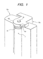
- the upper transfer guide 103 is provided with a receiving portion 104 (main body contact portion), which is in such a position as to impinge on a projection 101 (cartridge contact portion) or an arc-shaped portion 102 (cartridge contact portion) provided in the frame of the process cartridge B as shown in Fig. 1 when the upper transfer guide 103 is in the standing position or when the process cartridge is removed while the upper transfer guide 103 is lifted by a jammed recording sheet 2.
- the receiving portion 104 is used for turning down the upper transfer guide 103 in the standing position or pressing down the upper transfer guide 103 pushed up by the jammed recording sheet 2.
- the projection 101 and the arc-shaped portion 102 mentioned above are formed integrally with the cleaning frame 12c or separately formed and fixed thereto.
- the projection 101 and the arc-shaped portion 102 are integrally formed with the cleaning frame 13c.
- the frame of the process cartridge B is shaped as shown in Fig. 1.
- the shape of the frame is at first featured by the presence of the projection 101 in a position in front of the photosensitive drum 7 in the inserting direction of the process cartridge B, and outside the conveying area of the recording sheet in the longitudinal direction (axial direction of the photosensitive drum 7).
- the operator in case of sheet jamming under the upper transfer guide 103, the operator at first detaches the process cartridge. Then the operator lifts the upper transfer guide 103 and removes the jammed sheet. In mounting the detached process cartridge again after the jammed sheet disposal, the operator may forget to return the standing upper transfer guide 103 to the original position and may insert the process cartridge B while the upper transfer guide 103 is still in the standing position.
- the projection 101 (cartridge contact portion) is provided in a position in front of the photosensitive drum 7 in the inserting direction of the process cartridge, and outside the conveying area of the recording sheet in the longitudinal direction of the photosensitive drum 7.
- the receiving portion 104 (main body contact portion) of the upper transfer guide 103 is provided in a position impinging on the projection 101.
- the projection 101 impinges on the receiving portion 104 of the standing upper transfer guide 103 earlier than the photosensitive drum 7 thereby pressing down the upper transfer guide 103. It is therefore rendered possible to prevent the photosensitive drum 7 from impinging on the guide 103 and to protect the photosensitive drum 7 from being damaged.
- the projection 101 presses down the upper transfer guide 103 to return the same to the position prior to the generation of the sheet jamming. Therefore, the process cartridge B can be mounted and the image forming operation can be started immediately.
- the projection 101 is positioned outside the conveying area of the recording sheet in the longitudinal direction of the photosensitive drum 7. For this reason it does not hinder the conveyance of the recording sheet.
- the groove 105 is provided in the frame for allowing entry of the projection 101 as shown in Fig. 5.
- the shape of the frame of the present embodiment is secondly featured by a fact that the frame supporting the photosensitive drum 7 has an arc-shaped portion 102c.
- the arc-shaped portion 102c is provided in a position behind the photosensitive drum in the inserting direction of the process cartridge and outside the conveying area of the recording sheet in the longitudinal direction of the photosensitive drum 7. Also it is concentric with the photosensitive drum and has a larger radius than that of the photosensitive drum.
- the upper transfer guide 103 since the upper transfer guide 103 is rotatably mounted on the shaft 3cl of the paired convey rollers 3c as explained in the foregoing, the upper transfer guide 103 may be lifted up by the jammed recording sheet 2 in case of sheet jamming under the upper transfer guide 103.
- the upper transfer guide 103 can only be lifted to a position impinging on a corner 106 of the developing unit as shown in Fig. 8.
- the cleaning frame 12c supporting the photosensitive drum 7 is provided with the arc-shaped portion 102. Consequently when the operator detaches the process cartridge B, the arc-shaped portion 102 comes into contact with the receiving portion 104 so as to press down the upper transfer guide 103 as shown in Fig. 9. Therefore the detaching operation of the process cartridge B is not hindered.
- the photosensitive drum 7 is protected from being damaged by the upper transfer guide 103.
- the arc-shaped portion 102 is not limited to the arc shape as long as it is so shaped as to press down the upper transfer guide 103 by impingement on the receiving portion 104 thereof and as to be outside the photosensitive drum 7 in the axial direction thereof.
- a process cartridge (B) is adapted for use in a main body of an electrophotographic image forming apparatus for forming an image on a recording medium (for example, recording sheet 2) and provided with a guide member (for example, transfer upper guide 103) which is to guide the recording medium in the conveying direction thereof and which can assume either a guide position for guiding the recording medium in the conveying direction thereof or a retracted position retracted from the guide position.
- a guide member for example, transfer upper guide 103
- the cartridge comprising a cartridge frame (for example, cleaning frame 12c), an electrophotographic photosensitive member (7), process means (for example, charge means 8, developer means 10 and cleaning means) for acting on the electrophotographic photosensitive member, and a cartridge contact portion (for example, protrusion 102) to impinge on a main body contact portion (for example, receive portion 104) provided on the guide member if the guide member is in the retracted position in mounting the process cartridge in the main body of the apparatus to shift the guide member to the guide position, the cartridge contact portion is provided on the cartridge frame.
- a cartridge frame for example, cleaning frame 12c
- process means for example, charge means 8, developer means 10 and cleaning means
- a cartridge contact portion for example, protrusion 102
- main body contact portion for example, receive portion 104
- the cartridge contact portion (for example, protrusion 102) is provided at an end side in the axial direction of the drum-shaped electrophotographic photosensitive member, in such a manner as to protrude forward of the electrophotogrphic photosensitive member (7) in mounting the process cartridge (B) on the main body of the apparatus.
- the cartridge contact portion (for example, protrusion 102) is provided in such a manner as to protrude downwards from the electrophotographic photosensitive member (7) in mounting the process cartridge (B) in the main body of the apparatus.
- the process cartridge further comprises a helical gear (7b) for transmitting the driving force, received by the process cartridge (B) from the apparatus, to a developing roller, at the end side in the axial direction of the electrophotographic photosensitive member, wherein the developing roller (10b) is provided for developing a latent image formed on the electrophotographic photosensitive member.
- the cartridge contact portion (for example, protrusion 102) is provided outside the helical gear in the axial direction of the electrophotographic photosensitive member (7), and is made of a plastic material and is integrally formed with the cartridge frame of a plastic material.
- the cartridge contact portion protruding from the cartridge frame has a substantially triangular shape.
- the process cartridge comprises by combining the charge means, develop means or clean means and the electrophotographic photosensitive member; combining at least one of the charge means, develop means and clean means and the electrophotographic photosensitive member; or combining at least the develop means and the electrophotographic photosensitive member, respectively into the cartridge which is removably mounted on the main body of the image forming apparatus.
- All of the above toner container 12a, developing frame 12b, cleaning frame 12c, protruded portion (projection) 101 and arc-shaped portion 102 are made of the plastic material, which may be the polystylene, ABS resin (acrylonitrile/butadiene/styrene copolymer), polycarbonate, polyethylene or polypropylene.
- projection 101 is not limited to the triangular, but can have another various shape. Also, the projection 101 can be provided, other than the cleaning frame, on the cartridge frame which includes the cleaning frame, developing frame and toner container and forms the cartridge.
- the electrophotographic photosensitive member is not damaged nor is hindered when removing the cartridge from the main body of the image forming apparatus, even in case the process cartridge is detached while the guide member is pushed out of the conveying path by a sheet jam in the part of such guide member, or in case the process cartridge is mounted without returning the guide member to the original position after the jammed sheet disposal.
- the present invention allows to improve the mountability and operability of the process cartridge with respect to the main apparatus.
Landscapes
- Engineering & Computer Science (AREA)
- Computer Vision & Pattern Recognition (AREA)
- Physics & Mathematics (AREA)
- General Physics & Mathematics (AREA)
- Electrophotography Configuration And Component (AREA)
- Paper Feeding For Electrophotography (AREA)
- Electrostatic Charge, Transfer And Separation In Electrography (AREA)
Applications Claiming Priority (6)
| Application Number | Priority Date | Filing Date | Title |
|---|---|---|---|
| JP33127497 | 1997-11-14 | ||
| JP33127497 | 1997-11-14 | ||
| JP331274/97 | 1997-11-14 | ||
| JP332069/98 | 1998-11-06 | ||
| JP33206998A JP3787445B2 (ja) | 1997-11-14 | 1998-11-06 | プロセスカ―トリッジ及び電子写真画像形成装置 |
| JP33206998 | 1998-11-06 |
Publications (3)
| Publication Number | Publication Date |
|---|---|
| EP0917027A2 EP0917027A2 (en) | 1999-05-19 |
| EP0917027A3 EP0917027A3 (en) | 2000-03-01 |
| EP0917027B1 true EP0917027B1 (en) | 2004-10-20 |
Family
ID=26573797
Family Applications (1)
| Application Number | Title | Priority Date | Filing Date |
|---|---|---|---|
| EP98309256A Expired - Lifetime EP0917027B1 (en) | 1997-11-14 | 1998-11-12 | Process cartridge and electrophotographic image forming apparatus |
Country Status (6)
| Country | Link |
|---|---|
| US (1) | US6009288A (enExample) |
| EP (1) | EP0917027B1 (enExample) |
| JP (1) | JP3787445B2 (enExample) |
| CN (1) | CN1145847C (enExample) |
| AU (1) | AU739976B2 (enExample) |
| DE (1) | DE69827098T2 (enExample) |
Families Citing this family (12)
| Publication number | Priority date | Publication date | Assignee | Title |
|---|---|---|---|---|
| US6714746B2 (en) | 2001-01-23 | 2004-03-30 | Canon Kabushiki Kaisha | Image forming apparatus rotationally driving image bearing member and contact electrifying member of process cartridge and process cartridge comprising image bearing member and contact electrifying member |
| JP4136481B2 (ja) * | 2002-06-19 | 2008-08-20 | キヤノン株式会社 | 現像装置及び画像形成装置 |
| JP4018517B2 (ja) * | 2002-11-29 | 2007-12-05 | キヤノン株式会社 | 部品 |
| JP4047208B2 (ja) * | 2003-03-27 | 2008-02-13 | キヤノン株式会社 | 画像形成装置 |
| JP2006208838A (ja) | 2005-01-28 | 2006-08-10 | Brother Ind Ltd | プロセスカートリッジ、現像カートリッジおよび画像形成装置 |
| JP2007212520A (ja) * | 2006-02-07 | 2007-08-23 | Kyocera Mita Corp | 画像形成装置 |
| JP4963733B2 (ja) | 2009-08-04 | 2012-06-27 | キヤノン株式会社 | 画像形成装置及びカートリッジ |
| JP4605822B1 (ja) | 2009-12-14 | 2011-01-05 | キヤノン株式会社 | 電子写真画像形成装置 |
| JP5825770B2 (ja) * | 2009-12-24 | 2015-12-02 | キヤノン株式会社 | ユニット及び電子写真画像形成装置 |
| US8515309B2 (en) | 2009-12-25 | 2013-08-20 | Brother Kogyo Kabushiki Kaisha | Process cartridge, developing cartridge and image forming apparatus |
| JP5684679B2 (ja) * | 2011-08-25 | 2015-03-18 | 株式会社沖データ | 画像形成装置 |
| JP6602069B2 (ja) * | 2015-06-19 | 2019-11-06 | キヤノン株式会社 | 画像形成装置 |
Family Cites Families (7)
| Publication number | Priority date | Publication date | Assignee | Title |
|---|---|---|---|---|
| JPS62299868A (ja) * | 1986-06-19 | 1987-12-26 | Canon Inc | 画像形成装置及びこの装置に使用するプロセスカートリッジ |
| JPS634252A (ja) * | 1986-06-24 | 1988-01-09 | Canon Inc | プロセスカ−トリツジ及びこのカ−トリツジを使用する画像形成装置 |
| US5319418A (en) * | 1989-05-19 | 1994-06-07 | Fujitsu Limited | Image forming apparatus |
| US5493366A (en) * | 1990-09-07 | 1996-02-20 | Konica Corporation | Image forming apparatus |
| US5245394A (en) * | 1991-03-20 | 1993-09-14 | Konica Corporation | Image forming apparatus having an openable conveyance path |
| US5893006A (en) * | 1995-07-31 | 1999-04-06 | Canon Kabushiki Kaisha | Process cartridge detectably mountable to image forming apparatus and image forming apparatus using same |
| JPH09106125A (ja) * | 1995-10-09 | 1997-04-22 | Canon Inc | 電子写真画像形成装置及びプロセスカートリッジ |
-
1998
- 1998-11-06 JP JP33206998A patent/JP3787445B2/ja not_active Expired - Fee Related
- 1998-11-12 EP EP98309256A patent/EP0917027B1/en not_active Expired - Lifetime
- 1998-11-12 US US09/190,115 patent/US6009288A/en not_active Expired - Lifetime
- 1998-11-12 DE DE69827098T patent/DE69827098T2/de not_active Expired - Lifetime
- 1998-11-13 CN CNB981241778A patent/CN1145847C/zh not_active Expired - Fee Related
- 1998-11-13 AU AU92379/98A patent/AU739976B2/en not_active Ceased
Also Published As
| Publication number | Publication date |
|---|---|
| CN1145847C (zh) | 2004-04-14 |
| CN1217485A (zh) | 1999-05-26 |
| US6009288A (en) | 1999-12-28 |
| JP3787445B2 (ja) | 2006-06-21 |
| AU739976B2 (en) | 2001-10-25 |
| EP0917027A2 (en) | 1999-05-19 |
| AU9237998A (en) | 1999-06-03 |
| DE69827098D1 (de) | 2004-11-25 |
| DE69827098T2 (de) | 2005-10-20 |
| JPH11224042A (ja) | 1999-08-17 |
| EP0917027A3 (en) | 2000-03-01 |
Similar Documents
| Publication | Publication Date | Title |
|---|---|---|
| CN100468220C (zh) | 电子照相成像设备、处理盒以及显影盒 | |
| US4888620A (en) | Process cartridge and image forming apparatus using the same | |
| US6453135B1 (en) | Image forming apparatus having a transfer material carrier unit or an intermediate transfer body unit | |
| US8565642B2 (en) | Electrophotographic image forming apparatus | |
| JP4446106B2 (ja) | 電子写真式印刷アセンブリ及び電子写真式印刷装置用のシール | |
| EP0917027B1 (en) | Process cartridge and electrophotographic image forming apparatus | |
| US4655578A (en) | Reproducing apparatus cartridge mounting assembly | |
| US6661977B1 (en) | Electrophotographic image forming apparatus and process cartridge | |
| EP0590941B1 (en) | Image-forming apparatus | |
| EP0454163B1 (en) | Toner container and process unit including the same | |
| US6980756B2 (en) | Process cartridge, electrophotographic image forming apparatus, and process cartridge mounting system | |
| EP0418085B1 (en) | Duplex feeder with side shifting inversion | |
| JP3200139B2 (ja) | プロセスカートリッジ及び前記プロセスカートリッジを装着可能な画像形成装置 | |
| JPH0478888A (ja) | 電子写真装置の感光体取付構造 | |
| JPH1055128A (ja) | 静電写真式複製機用の残留トナー回収サンプ装置 | |
| JP3194335B2 (ja) | クリーニング装置 | |
| JP2025010291A (ja) | 画像形成装置 | |
| JP3457775B2 (ja) | 電子写真装置 | |
| JP7541869B2 (ja) | 画像形成装置 | |
| JP7541870B2 (ja) | 画像形成装置 | |
| JPH0990694A (ja) | クリーニング装置及びプロセスカートリッジ | |
| JP3654788B2 (ja) | 画像形成装置 | |
| JP3192484B2 (ja) | プロセスカートリッジ及びこのプロセスカートリッジを着脱可能な画像形成装置 | |
| JP2544028Y2 (ja) | 電子写真装置 | |
| US9733591B2 (en) | Image forming apparatus |
Legal Events
| Date | Code | Title | Description |
|---|---|---|---|
| PUAI | Public reference made under article 153(3) epc to a published international application that has entered the european phase |
Free format text: ORIGINAL CODE: 0009012 |
|
| AK | Designated contracting states |
Kind code of ref document: A2 Designated state(s): CH DE FR GB IT LI |
|
| AX | Request for extension of the european patent |
Free format text: AL;LT;LV;MK;RO;SI |
|
| PUAL | Search report despatched |
Free format text: ORIGINAL CODE: 0009013 |
|
| AK | Designated contracting states |
Kind code of ref document: A3 Designated state(s): AT BE CH CY DE DK ES FI FR GB GR IE IT LI LU MC NL PT SE |
|
| AX | Request for extension of the european patent |
Free format text: AL;LT;LV;MK;RO;SI |
|
| 17P | Request for examination filed |
Effective date: 20000718 |
|
| AKX | Designation fees paid |
Free format text: CH DE FR GB IT LI |
|
| 17Q | First examination report despatched |
Effective date: 20021220 |
|
| GRAP | Despatch of communication of intention to grant a patent |
Free format text: ORIGINAL CODE: EPIDOSNIGR1 |
|
| RTI1 | Title (correction) |
Free format text: PROCESS CARTRIDGE AND ELECTROPHOTOGRAPHIC IMAGE FORMING APPARATUS |
|
| GRAS | Grant fee paid |
Free format text: ORIGINAL CODE: EPIDOSNIGR3 |
|
| GRAA | (expected) grant |
Free format text: ORIGINAL CODE: 0009210 |
|
| AK | Designated contracting states |
Kind code of ref document: B1 Designated state(s): CH DE FR GB IT LI |
|
| PG25 | Lapsed in a contracting state [announced via postgrant information from national office to epo] |
Ref country code: LI Free format text: LAPSE BECAUSE OF FAILURE TO SUBMIT A TRANSLATION OF THE DESCRIPTION OR TO PAY THE FEE WITHIN THE PRESCRIBED TIME-LIMIT Effective date: 20041020 Ref country code: IT Free format text: LAPSE BECAUSE OF FAILURE TO SUBMIT A TRANSLATION OF THE DESCRIPTION OR TO PAY THE FEE WITHIN THE PRE;WARNING: LAPSES OF ITALIAN PATENTS WITH EFFECTIVE DATE BEFORE 2007 MAY HAVE OCCURRED AT ANY TIME BEFORE 2007. THE CORRECT EFFECTIVE DATE MAY BE DIFFERENT FROM THE ONE RECORDED.SCRIBED TIME-LIMIT Effective date: 20041020 Ref country code: CH Free format text: LAPSE BECAUSE OF FAILURE TO SUBMIT A TRANSLATION OF THE DESCRIPTION OR TO PAY THE FEE WITHIN THE PRESCRIBED TIME-LIMIT Effective date: 20041020 |
|
| REG | Reference to a national code |
Ref country code: GB Ref legal event code: FG4D |
|
| REG | Reference to a national code |
Ref country code: CH Ref legal event code: EP |
|
| REF | Corresponds to: |
Ref document number: 69827098 Country of ref document: DE Date of ref document: 20041125 Kind code of ref document: P |
|
| REG | Reference to a national code |
Ref country code: CH Ref legal event code: PL |
|
| ET | Fr: translation filed | ||
| PLBE | No opposition filed within time limit |
Free format text: ORIGINAL CODE: 0009261 |
|
| STAA | Information on the status of an ep patent application or granted ep patent |
Free format text: STATUS: NO OPPOSITION FILED WITHIN TIME LIMIT |
|
| 26N | No opposition filed |
Effective date: 20050721 |
|
| PGFP | Annual fee paid to national office [announced via postgrant information from national office to epo] |
Ref country code: FR Payment date: 20101207 Year of fee payment: 13 |
|
| REG | Reference to a national code |
Ref country code: FR Ref legal event code: ST Effective date: 20120731 |
|
| PG25 | Lapsed in a contracting state [announced via postgrant information from national office to epo] |
Ref country code: FR Free format text: LAPSE BECAUSE OF NON-PAYMENT OF DUE FEES Effective date: 20111130 |
|
| PGFP | Annual fee paid to national office [announced via postgrant information from national office to epo] |
Ref country code: DE Payment date: 20151130 Year of fee payment: 18 Ref country code: GB Payment date: 20151125 Year of fee payment: 18 |
|
| REG | Reference to a national code |
Ref country code: DE Ref legal event code: R119 Ref document number: 69827098 Country of ref document: DE |
|
| GBPC | Gb: european patent ceased through non-payment of renewal fee |
Effective date: 20161112 |
|
| PG25 | Lapsed in a contracting state [announced via postgrant information from national office to epo] |
Ref country code: GB Free format text: LAPSE BECAUSE OF NON-PAYMENT OF DUE FEES Effective date: 20161112 Ref country code: DE Free format text: LAPSE BECAUSE OF NON-PAYMENT OF DUE FEES Effective date: 20170601 |