EP0916832B1 - Gekühlter Ringträger - Google Patents
Gekühlter Ringträger Download PDFInfo
- Publication number
- EP0916832B1 EP0916832B1 EP98119585A EP98119585A EP0916832B1 EP 0916832 B1 EP0916832 B1 EP 0916832B1 EP 98119585 A EP98119585 A EP 98119585A EP 98119585 A EP98119585 A EP 98119585A EP 0916832 B1 EP0916832 B1 EP 0916832B1
- Authority
- EP
- European Patent Office
- Prior art keywords
- ring carrier
- sheet metal
- cooling duct
- metal cooling
- faces
- Prior art date
- Legal status (The legal status is an assumption and is not a legal conclusion. Google has not performed a legal analysis and makes no representation as to the accuracy of the status listed.)
- Expired - Lifetime
Links
- 239000002184 metal Substances 0.000 claims description 49
- 238000001816 cooling Methods 0.000 claims description 46
- 238000003466 welding Methods 0.000 claims description 18
- 238000000034 method Methods 0.000 claims description 4
- 238000005476 soldering Methods 0.000 claims description 2
- 238000002485 combustion reaction Methods 0.000 claims 1
- 239000000969 carrier Substances 0.000 description 4
- 229910000831 Steel Inorganic materials 0.000 description 2
- 239000000155 melt Substances 0.000 description 2
- 239000010959 steel Substances 0.000 description 2
- 238000005452 bending Methods 0.000 description 1
- 230000015572 biosynthetic process Effects 0.000 description 1
- 239000000945 filler Substances 0.000 description 1
- 239000007789 gas Substances 0.000 description 1
- 238000010438 heat treatment Methods 0.000 description 1
- 210000001503 joint Anatomy 0.000 description 1
- 238000003825 pressing Methods 0.000 description 1
- 238000007789 sealing Methods 0.000 description 1
- 230000007704 transition Effects 0.000 description 1
Images
Classifications
-
- F—MECHANICAL ENGINEERING; LIGHTING; HEATING; WEAPONS; BLASTING
- F16—ENGINEERING ELEMENTS AND UNITS; GENERAL MEASURES FOR PRODUCING AND MAINTAINING EFFECTIVE FUNCTIONING OF MACHINES OR INSTALLATIONS; THERMAL INSULATION IN GENERAL
- F16J—PISTONS; CYLINDERS; SEALINGS
- F16J1/00—Pistons; Trunk pistons; Plungers
- F16J1/09—Pistons; Trunk pistons; Plungers with means for guiding fluids
-
- F—MECHANICAL ENGINEERING; LIGHTING; HEATING; WEAPONS; BLASTING
- F05—INDEXING SCHEMES RELATING TO ENGINES OR PUMPS IN VARIOUS SUBCLASSES OF CLASSES F01-F04
- F05C—INDEXING SCHEME RELATING TO MATERIALS, MATERIAL PROPERTIES OR MATERIAL CHARACTERISTICS FOR MACHINES, ENGINES OR PUMPS OTHER THAN NON-POSITIVE-DISPLACEMENT MACHINES OR ENGINES
- F05C2201/00—Metals
- F05C2201/04—Heavy metals
- F05C2201/0433—Iron group; Ferrous alloys, e.g. steel
- F05C2201/0448—Steel
Definitions
- the invention relates to a cooled ring carrier according to the The preamble of claim 1.
- a ring carrier is known from DE-PS 26 24 412.
- a generic ring carrier is also from the US 4,907,545 known, the sheet also by welding or soldering is attached to the ring carrier.
- the sheet also by welding or soldering is attached to the ring carrier.
- the sheet also by welding or soldering is attached to the ring carrier.
- the sheet also by welding or soldering is attached to the ring carrier.
- the figures 1 and 4 of the writing sits on the sheet with a blunt joint the radially inner wall or on this wall Web of the ring carrier, in Fig. 5, 6 and 7 that Sheet metal flat on flat or curved surfaces of the ring carrier created. All illustrated embodiments is common that the sheet either before welding by using temperature differences in the Ring bearer must be shrunk or that it Welding must be tightened and that the weld cross-sections are relatively small.
- a disadvantage when shrinking with a blunt impact is also that the relatively thin Sheet metal is subjected to buckling.
- Ring carriers of the generic type are also from JP-OS 05-240347 and EP 791 738. With these too the sheet forming the cooling channel using temperature differences either in the circular cylindrical, radial inner surface of the ring carrier or in recesses or grooves of the ring carrier shrunk.
- the invention is therefore concerned with the problem of a Sheet metal cooling channel before welding with a ring carrier like this to attach to this that a secure, tight welded joint arise between the ring carrier and the sheet metal cooling duct can that clamping devices can be omitted during welding and that on shrinking using temperature differences can be dispensed with.
- a sheet metal cooling duct a sheet metal part is also referred to, which has a circumferential, has an opening facing the ring carrier.
- the Difference in diameter between ring carrier and sheet metal cooling duct can e.g. B. 0.4 mm, the elastic portion the deformation when pressed in is approx. 0.15 to 0.2 mm, a certain amount of plastic deformation of the Sheet metal cooling channel is added when pressing.
- the radially inward facing surface of the ring carrier of which the sheet metal cooling duct is clamped can also consist of two circular cylindrical partial surfaces with different diameters consist. In this case, the two have the ring bearer contacting edges or surfaces also one different diameters.
- the basic idea of the invention is the elastic properties the sheet for bracing in the ring carrier and a correspondingly safe welding of ring carriers and Use the sheet metal cooling duct without shrinking the sheet metal cooling duct using temperature differences - cooling the sheet metal cooling duct and / or heating the ring carrier. If the edges contacting the ring carrier or areas of the sheet metal cooling duct with a relatively small Angles are brought up to the inner surface of the ring carrier, then the sheet metal cooling duct - although its outside diameter immediately before assembly is larger than the inside diameter of the ring carrier - with a mounting device pressed into the ring carrier in the prestressed state become. With radially running edges of the cooling channel this procedure is not or only with great difficulty applicable.
- Another advantage of the invention is that the ring carrier its usual, in cross section - apart from the ring grooves to be pierced - keep approximately rectangular shape can and no special contours on the ring carrier back have to be turned on or cast on.
- filler metal can either can be supplied from the outside or in the form of a melt Edge already on the ring carrier. the goal is it, the wedge-shaped cross-section or gusset between Ring carrier and sheet metal cooling duct largely with Fill melt, so the probability of one pressure-tight connection becomes greatest.
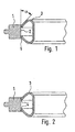
- the cooled ring carrier consists of a circular ring carrier 1 with a radially inward circular cylindrical Surface 2 and a sheet metal cooling channel 3 made of austenitic Steel made in one piece from a flat sheet steel is produced by plastic deformation.
- the sheet metal cooling channel 3 is before welding ring carrier 1 and Sheet metal cooling duct 3 with the help of a mounting device, not shown pressed into the ring carrier 1.
- the Mounting device designed so that the sheet metal cooling duct 3rd its axial diameter under axial pressure downsized - e.g. B. in a conical receptacle - and in such a preloaded condition from the assembly device in the ring carrier 1 can be pressed.
- the outside diameter of the sheet metal cooling duct is in front of the Press in approx. 0.35 mm larger than the inside diameter of the Ring carrier. This forms on the inner circumference when pressed in of the sheet metal cooling duct 3 tangential compressive stresses.
- the angle ⁇ between those facing inwards circular cylindrical surfaces 2 of the ring carrier 1 and the Sheet metal cooling duct 3 in the area of its two the ring carrier contacting edges 4 is 35 °. This leads to the sheet metal cooling channel press well into the ring carrier leaves and sits comparably tight in the ring carrier, like when shrinking using temperature differences.
Landscapes
- Engineering & Computer Science (AREA)
- General Engineering & Computer Science (AREA)
- Chemical & Material Sciences (AREA)
- Combustion & Propulsion (AREA)
- Mechanical Engineering (AREA)
- Gasket Seals (AREA)
- Pistons, Piston Rings, And Cylinders (AREA)
Description
- Fig. 1
- einen erfindungsgemäßen gekühlten Ringträger im Querschnitt vor dem Verschweißen von Ringträger und Blechkühlkanal
- Fig. 2
- den erfindungsgemäßen Ringträger in geschweißtem Zustand.
Claims (3)
- Gekühlter Ringträger (1) für einen Kolben eines Verbrennungsmotors mit mindestens einer radial nach innen weisenden, kreiszylindrischen Fläche (2) und einem durch Schweißen oder Löten an der bzw. den Flächen (2) befestigbaren Blechkühlkanal (3), der mit einer Preßpassung in den Ringträger (1) eingespannt ist und der zwei, den Ringträger (1) an der bzw. den radial nach innen weisenden Flächen (2) umlaufend kontaktierende Kanten bzw. Flächen (4) aufweist,
dadurch gekennzeichnet, daß der Winkel α zwischen der bzw. den nach innen weisenden Flächen (2) des Ringträgers (1) und dem Blechkühlkanal (3) im Bereich seiner beiden den Ringträger (1) kontaktierenden Kanten bzw. Flächen (4) kleiner als 45° ist. - Ringträger nach Anspruch 1,
dadurch gekennzeichnet, daß sich die Stirnseiten des Blechs etwa gegenüberliegen. - Verfahren zum Befestigen eines Blechkühlkanals (3) in einem Ringträger (1) mit mindestens einer.radial nach innen weisenden, kreiszylindrischen Fläche (2), wobei der Ringträger (1) und der Blechkühlkanal (3) gemeinsam einen geschlossenen Kühlkanal eines gekühlten Ringträgers für Kolben bilden und nach dem Befestigen miteinander verschweißt werden,
dadurch gekennzeichnet, daß zunächst der Blechkühlkanal (3) in einer Montagevorrichtung elastisch so verformt wird, daß er seinen Außendurchmesser verkleinert und er in diesem vorgespannten Zustand in den Ringträger (1) eingepreßt wird, wobei der Winkel α zwischen der bzw. den nach innen weisenden Flächen (2) des Ringträgers (1) und dem Blechkühlkanal (3) im Bereich seiner den Ringträger kontaktierenden Kanten bzw. Flächen (4) kleiner als 45° ist.
Applications Claiming Priority (2)
| Application Number | Priority Date | Filing Date | Title |
|---|---|---|---|
| DE19750021A DE19750021A1 (de) | 1997-11-12 | 1997-11-12 | Gekühlter Ringträger |
| DE19750021 | 1997-11-12 |
Publications (3)
| Publication Number | Publication Date |
|---|---|
| EP0916832A2 EP0916832A2 (de) | 1999-05-19 |
| EP0916832A3 EP0916832A3 (de) | 1999-12-29 |
| EP0916832B1 true EP0916832B1 (de) | 2002-12-18 |
Family
ID=7848422
Family Applications (1)
| Application Number | Title | Priority Date | Filing Date |
|---|---|---|---|
| EP98119585A Expired - Lifetime EP0916832B1 (de) | 1997-11-12 | 1998-10-16 | Gekühlter Ringträger |
Country Status (3)
| Country | Link |
|---|---|
| US (1) | US6105540A (de) |
| EP (1) | EP0916832B1 (de) |
| DE (2) | DE19750021A1 (de) |
Families Citing this family (16)
| Publication number | Priority date | Publication date | Assignee | Title |
|---|---|---|---|---|
| DE10009875C1 (de) * | 2000-03-01 | 2001-06-07 | Ks Kolbenschmidt Gmbh | Gekühlter Ringträger |
| DE10015709B4 (de) * | 2000-03-29 | 2011-08-11 | KS Kolbenschmidt GmbH, 74172 | Kolben mit einem ringförmigen Kühlkanal |
| DE10057366A1 (de) * | 2000-11-18 | 2002-05-23 | Mahle Gmbh | Verfahren zur gießtechnischen Herstellung eines Kolbens mit einem gekühlten Ringträger |
| DE10100955A1 (de) | 2001-01-11 | 2002-07-18 | Mahle Gmbh | Verfahren zur Herstellung eines Ringträgers mit angeschweißtem Blechkühlkanal |
| DE10128461C2 (de) * | 2001-06-12 | 2003-12-11 | Ks Kolbenschmidt Gmbh | Gekühlter Ringträger |
| DE20210600U1 (de) * | 2001-07-06 | 2002-12-05 | a.i.m.l. GmbH, 09514 Lengefeld | Kühlbarer Ringträger für innengekühlte Kolbenringe |
| DE10134293B4 (de) * | 2001-07-14 | 2009-06-04 | Mahle Gmbh | Gekühlter Ringträger für einen Kolben |
| ES2239241T3 (es) * | 2001-07-30 | 2005-09-16 | Roberto Oscar Appo | Metodo de montaje de un anillo de lamina metalica ensamblado y soldado en un aro portador, para conformar el conducto anular refrigerante de un piston de motor de combustion interna, y metodo para fabricar un anillo de lamina metalica ensamblado con un aro portador. |
| WO2003054371A1 (de) | 2001-12-21 | 2003-07-03 | Karl Merz | Kolbenringträger mit kühlkanal |
| US6938604B2 (en) * | 2003-10-06 | 2005-09-06 | Mahle Gmbh | Cooling channel cover for a one-piece piston of an internal combustion engine |
| DE102008031863A1 (de) | 2008-07-05 | 2010-01-07 | Mahle International Gmbh | Einlegeteil für einen Kolben eines Verbrennungsmotors sowie mit dem Einlegeteil versehener Kolben oder Kolbenkopf |
| DE102008031864A1 (de) | 2008-07-05 | 2010-01-07 | Mahle International Gmbh | Einlegteil für einen Kolben eines Verbrennungsmotors sowie mit dem Einlegeteil versehener Kolben oder Kolbenkopf |
| DE102008031862A1 (de) | 2008-07-05 | 2010-01-07 | Mahle International Gmbh | Einlegeteil für einen Kolben eines Verbrennungsmotors sowie mit dem Einlegeteil versehener Kolben oder Kolbenkopf |
| DE102010015568A1 (de) | 2010-04-19 | 2011-10-20 | Ks Kolbenschmidt Gmbh | Kolbenoberteil eines gebauten oder geschweißten Kolbens mit erweiterten Kühlräumen |
| DE102013201415A1 (de) | 2013-01-29 | 2014-07-31 | Ks Kolbenschmidt Gmbh | Brennkraftmaschine mit ölgekühltem Kolben und justierter Kraftstoff-Einspritzdüse |
| DE102013019506A1 (de) * | 2013-11-21 | 2015-06-03 | Mahle International Gmbh | Ringträger für einen Kolben eines Verbrennungsmotors sowie Kolben für einen Verbrennungsmotor |
Family Cites Families (10)
| Publication number | Priority date | Publication date | Assignee | Title |
|---|---|---|---|---|
| DE7212560U (de) * | 1972-06-29 | Alcan Gmbh | Ringträger aus Schwermetall für Kolben | |
| IT1018796B (it) * | 1973-08-30 | 1977-10-20 | Motoren Turbinen Union | Ugello a getto libero |
| DE7617370U1 (de) * | 1976-05-31 | 1976-10-07 | Alcan Aluminiumwerk Nuernberg Gmbh, 6000 Frankfurt | Kolben, insbesondere fuer brennkraftmaschinen |
| DE2624412C3 (de) * | 1976-05-31 | 1983-12-01 | Alcan Aluminiumwerk Nürnberg GmbH, 6000 Frankfurt | Verfahren zur Herstellung von Kolben mit einem Ringkanal |
| US4907545A (en) * | 1988-12-28 | 1990-03-13 | Caterpillar Inc. | Liquid cooled piston ring carrier assembly and piston using same |
| JPH05240347A (ja) * | 1992-02-26 | 1993-09-17 | Hino Motors Ltd | エンジン用ピストン耐摩環 |
| JP3349020B2 (ja) * | 1995-08-14 | 2002-11-20 | 日野自動車株式会社 | 薄板リング成形体の製造方法及び装置 |
| DE19548811A1 (de) * | 1995-12-27 | 1997-07-03 | Mahle Gmbh | Tauchkolben mit Kühlkanal |
| JPH09287517A (ja) * | 1996-04-22 | 1997-11-04 | Unisia Jecs Corp | 内燃機関用ピストン及びその内燃機関用ピストンの金型 |
| DE19722053C2 (de) * | 1997-05-27 | 2002-10-24 | Ks Kolbenschmidt Gmbh | Kolben für einen Verbrennungsmotor |
-
1997
- 1997-11-12 DE DE19750021A patent/DE19750021A1/de not_active Withdrawn
-
1998
- 1998-10-16 EP EP98119585A patent/EP0916832B1/de not_active Expired - Lifetime
- 1998-10-16 DE DE59806707T patent/DE59806707D1/de not_active Expired - Lifetime
- 1998-11-06 US US09/187,667 patent/US6105540A/en not_active Expired - Lifetime
Also Published As
| Publication number | Publication date |
|---|---|
| DE59806707D1 (de) | 2003-01-30 |
| US6105540A (en) | 2000-08-22 |
| EP0916832A2 (de) | 1999-05-19 |
| DE19750021A1 (de) | 1999-05-20 |
| EP0916832A3 (de) | 1999-12-29 |
Similar Documents
| Publication | Publication Date | Title |
|---|---|---|
| EP0916832A2 (de) | Gekühlter Ringträger | |
| DE69214393T2 (de) | Metalldichtung | |
| DE60018503T2 (de) | Druckspeicher und dessen Herstellungsverfahren | |
| DE69203831T2 (de) | Verfahren zum Verbinden von zwei Teilen entlang aneinander-stossender Kanten und damit hergestellte Verbindung. | |
| EP0877183B1 (de) | Metallische Zylinderkopfdichtung | |
| EP0942794B1 (de) | Verfahren zur herstellung eines formteiles | |
| EP0882191B1 (de) | Zylinderkopfdichtung mit einer mehrere metallblechlagen aufweisenden dichtungsplatte | |
| EP2288831B1 (de) | Flachdichtung | |
| EP1153840B1 (de) | Verfahren zum Herstellen eines Ringteils aus Blech für einen Dosendeckel | |
| DE10023149A1 (de) | Hochdruckkraftstoffeinspritzrohr für Dieselmotoren | |
| DE69114260T2 (de) | Rohrverbindung und Verfahren dazu. | |
| DE10130726C2 (de) | Verfahren und Einrichtung zur Herstellung einer Verbindung zwischen sich überlappenden plattenförmigen Bauteilen | |
| DE19750067B4 (de) | Verfahren zum Fügen eines Bauteils an einen Hohlkörper und dadurch herstellbarer Halter-Rohrelement-Komplex | |
| DE4444572C2 (de) | Verfahren zur Befestigung eines Anschlagringes am Ende eines Rohres | |
| EP1815170B1 (de) | Flachdichtung | |
| EP0376161B1 (de) | Verfahren und Hilfsvorrichtung zur Herstellung von Stumpfschweissnähten an gasführenden Rohrleitungen | |
| DE19640754B4 (de) | Strahlgeschweißter Verbund eines Karosseriebleches mit einem Rollprofil und Verfahren zu dessen Herstellung | |
| DE19715327A1 (de) | Verfahren zum Ausbilden eines Wulstes an einem Muffenrohrende | |
| EP0957256B1 (de) | Ringträger für einen Kolben eines Verbrennungsmotors | |
| EP1274924B1 (de) | Verfahren und vorrichtung zur herstellung eines katalysators mit einem einen polygonen querschnitt aufweisenden monolithen | |
| EP0959274A2 (de) | Zylinderkopfdichtung | |
| DE102021131248A1 (de) | Verfahren zum Verschweißen eines Schaftes mit einem geformten Blech einer Abflachung | |
| EP1475553B1 (de) | Luftfeder mit integriertem Druckanschlag | |
| DE29716233U1 (de) | Zentrier-, Spann- und Formiervorrichtung für miteinander zu verschweißende Rohrabschnitte | |
| DE4029325C2 (de) |
Legal Events
| Date | Code | Title | Description |
|---|---|---|---|
| PUAI | Public reference made under article 153(3) epc to a published international application that has entered the european phase |
Free format text: ORIGINAL CODE: 0009012 |
|
| AK | Designated contracting states |
Kind code of ref document: A2 Designated state(s): DE FR GB |
|
| AX | Request for extension of the european patent |
Free format text: AL;LT;LV;MK;RO;SI |
|
| PUAL | Search report despatched |
Free format text: ORIGINAL CODE: 0009013 |
|
| AK | Designated contracting states |
Kind code of ref document: A3 Designated state(s): AT BE CH CY DE DK ES FI FR GB GR IE IT LI LU MC NL PT SE |
|
| AX | Request for extension of the european patent |
Free format text: AL;LT;LV;MK;RO;SI |
|
| 17P | Request for examination filed |
Effective date: 20000120 |
|
| AKX | Designation fees paid |
Free format text: DE FR GB |
|
| GRAG | Despatch of communication of intention to grant |
Free format text: ORIGINAL CODE: EPIDOS AGRA |
|
| GRAG | Despatch of communication of intention to grant |
Free format text: ORIGINAL CODE: EPIDOS AGRA |
|
| GRAH | Despatch of communication of intention to grant a patent |
Free format text: ORIGINAL CODE: EPIDOS IGRA |
|
| 17Q | First examination report despatched |
Effective date: 20020625 |
|
| GRAH | Despatch of communication of intention to grant a patent |
Free format text: ORIGINAL CODE: EPIDOS IGRA |
|
| GRAA | (expected) grant |
Free format text: ORIGINAL CODE: 0009210 |
|
| AK | Designated contracting states |
Kind code of ref document: B1 Designated state(s): DE FR GB |
|
| REG | Reference to a national code |
Ref country code: GB Ref legal event code: FG4D Free format text: NOT ENGLISH |
|
| GBT | Gb: translation of ep patent filed (gb section 77(6)(a)/1977) |
Effective date: 20021218 |
|
| REF | Corresponds to: |
Ref document number: 59806707 Country of ref document: DE Date of ref document: 20030130 Kind code of ref document: P Ref document number: 59806707 Country of ref document: DE Date of ref document: 20030130 |
|
| ET | Fr: translation filed | ||
| PLBE | No opposition filed within time limit |
Free format text: ORIGINAL CODE: 0009261 |
|
| STAA | Information on the status of an ep patent application or granted ep patent |
Free format text: STATUS: NO OPPOSITION FILED WITHIN TIME LIMIT |
|
| 26N | No opposition filed |
Effective date: 20030919 |
|
| REG | Reference to a national code |
Ref country code: FR Ref legal event code: PLFP Year of fee payment: 18 |
|
| REG | Reference to a national code |
Ref country code: FR Ref legal event code: PLFP Year of fee payment: 19 |
|
| REG | Reference to a national code |
Ref country code: FR Ref legal event code: PLFP Year of fee payment: 20 |
|
| PGFP | Annual fee paid to national office [announced via postgrant information from national office to epo] |
Ref country code: FR Payment date: 20171031 Year of fee payment: 20 |
|
| PGFP | Annual fee paid to national office [announced via postgrant information from national office to epo] |
Ref country code: GB Payment date: 20171101 Year of fee payment: 20 |
|
| PGFP | Annual fee paid to national office [announced via postgrant information from national office to epo] |
Ref country code: DE Payment date: 20171229 Year of fee payment: 20 |
|
| REG | Reference to a national code |
Ref country code: DE Ref legal event code: R071 Ref document number: 59806707 Country of ref document: DE |
|
| REG | Reference to a national code |
Ref country code: GB Ref legal event code: PE20 Expiry date: 20181015 |
|
| PG25 | Lapsed in a contracting state [announced via postgrant information from national office to epo] |
Ref country code: GB Free format text: LAPSE BECAUSE OF EXPIRATION OF PROTECTION Effective date: 20181015 |