EP0916723B1 - Dispositif de pigeage pour cuves de vinification - Google Patents
Dispositif de pigeage pour cuves de vinification Download PDFInfo
- Publication number
- EP0916723B1 EP0916723B1 EP97440108A EP97440108A EP0916723B1 EP 0916723 B1 EP0916723 B1 EP 0916723B1 EP 97440108 A EP97440108 A EP 97440108A EP 97440108 A EP97440108 A EP 97440108A EP 0916723 B1 EP0916723 B1 EP 0916723B1
- Authority
- EP
- European Patent Office
- Prior art keywords
- dipping
- tools
- frame
- central axis
- vat
- Prior art date
- Legal status (The legal status is an assumption and is not a legal conclusion. Google has not performed a legal analysis and makes no representation as to the accuracy of the status listed.)
- Expired - Lifetime
Links
- 238000011514 vinification Methods 0.000 title claims description 6
- 238000007598 dipping method Methods 0.000 claims 14
- 238000005096 rolling process Methods 0.000 claims 1
- 238000004080 punching Methods 0.000 description 15
- 238000000034 method Methods 0.000 description 3
- 235000014101 wine Nutrition 0.000 description 3
- CURLTUGMZLYLDI-UHFFFAOYSA-N Carbon dioxide Chemical compound O=C=O CURLTUGMZLYLDI-UHFFFAOYSA-N 0.000 description 2
- 241000219094 Vitaceae Species 0.000 description 2
- 238000006073 displacement reaction Methods 0.000 description 2
- 238000000855 fermentation Methods 0.000 description 2
- 230000004151 fermentation Effects 0.000 description 2
- 235000021021 grapes Nutrition 0.000 description 2
- 239000007788 liquid Substances 0.000 description 2
- 229910000831 Steel Inorganic materials 0.000 description 1
- 241000219095 Vitis Species 0.000 description 1
- 235000009754 Vitis X bourquina Nutrition 0.000 description 1
- 235000012333 Vitis X labruscana Nutrition 0.000 description 1
- 235000014787 Vitis vinifera Nutrition 0.000 description 1
- 235000019568 aromas Nutrition 0.000 description 1
- 229910002092 carbon dioxide Inorganic materials 0.000 description 1
- 239000001569 carbon dioxide Substances 0.000 description 1
- 239000003086 colorant Substances 0.000 description 1
- 230000007423 decrease Effects 0.000 description 1
- 230000000694 effects Effects 0.000 description 1
- 239000000686 essence Substances 0.000 description 1
- 235000019674 grape juice Nutrition 0.000 description 1
- 239000000203 mixture Substances 0.000 description 1
- 230000000754 repressing effect Effects 0.000 description 1
- 239000007787 solid Substances 0.000 description 1
- 239000010959 steel Substances 0.000 description 1
Images

Classifications
-
- C—CHEMISTRY; METALLURGY
- C12—BIOCHEMISTRY; BEER; SPIRITS; WINE; VINEGAR; MICROBIOLOGY; ENZYMOLOGY; MUTATION OR GENETIC ENGINEERING
- C12G—WINE; PREPARATION THEREOF; ALCOHOLIC BEVERAGES; PREPARATION OF ALCOHOLIC BEVERAGES NOT PROVIDED FOR IN SUBCLASSES C12C OR C12H
- C12G1/00—Preparation of wine or sparkling wine
- C12G1/02—Preparation of must from grapes; Must treatment and fermentation
-
- C—CHEMISTRY; METALLURGY
- C12—BIOCHEMISTRY; BEER; SPIRITS; WINE; VINEGAR; MICROBIOLOGY; ENZYMOLOGY; MUTATION OR GENETIC ENGINEERING
- C12G—WINE; PREPARATION THEREOF; ALCOHOLIC BEVERAGES; PREPARATION OF ALCOHOLIC BEVERAGES NOT PROVIDED FOR IN SUBCLASSES C12C OR C12H
- C12G2200/00—Special features
- C12G2200/25—Preparation of wine or sparkling wine in vessels with movable equipment for mixing the content
Definitions
- the object of the present invention is, in the winery, a pegging device for wine tanks winemaking.
- the manual method consists in repressing the marc hat in the must by means of so-called poles "rods" fitted at the end of a disc or a stock that we stick in the hat.
- poles rods
- the maneuvering of poles is difficult and painful and this method is in also not very effective in terms of results.
- the document FR2614314 describes an apparatus for pegging not integrated in the tank including a pigging tool conical attached to the end of the rod of a picking cylinder allowing its displacement in the axial direction to make penetrate the drawing tool into the marc hat and put it in extract, and means ordered to ensure the displacement of said rod in the other two dimensions, said means being carried by a support capable to be immobilized in relation to a tank, then to be released and moved from this tank to another.
- this device is difficult to use for automatic operation by means of a programmable controller, due to the different travel phases to program to bring the punching tool in various places on the surface of the hat marc and especially near the internal edges of the tank. Also to reach the edges of the surface of the marc hat, the tool must be tilted, which decreases its efficiency.
- the object of the present invention is to remedy these disadvantages by proposing a device which makes it possible to perform punching down operations within time limits much lower than those obtained by methods and existing devices, with excellent efficiency.
- the punching device is of the type comprising a gantry-shaped frame supporting means of punching down and provided with means of bearing and motor means controlled by a unit control center, allowing the chassis to be moved above a row of tanks, from one tank to another, the axis central of the chassis being parallel to the axes of the tanks and substantially coaxial with the axis of the tank concerned during a pegging operation, and it is characterized in that the pegging means consist of at least two drawing tools located in a horizontal plane and connected between them by a movable horizontal bar on the one hand in vertical and mobile translation on the other hand around the axis central of the chassis so that at least one of the tools pickers is located near the edge of the tank during the punching down operation.
- the picking tools are circular plates.
- the horizontal bar which connects the drawing tools is secured at the end the rod of an eccentric cylinder, parallel to the central axis of the chassis and secured by means of a radial arm to a central shaft rotated by a motor around said central axis.
- the cylinder, the central shaft and the drive means of the chassis are controlled so that the support bar for punching down tools from a position out of the tank to a high position in the tank located substantially on the surface of the must.
- the cylinder and the shaft central are then operated to perform the operation of pigeage.
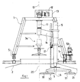
- the punching device comprises a gantry 1 which is mounted on casters 5 driven in rotation by a motor 50 and, of which the vertical central axis 10 is substantially coincident with the axis 20 of the tank 2 on which the gantry 1 is placed in position to perform the punching down operation; a vertical tree 11 which is moved to rotation around the axis 10 by a motor 12 placed in a casing 13 fixed at the top of the gantry 1 and which leads into rotation around its axis 10, via an arm 14 secured radially to the shaft 11, a vertical cylinder 15 whose end of the rod 16 is secured to a bar 3 horizontal carrying two picking tools 30.31 of which the face lower is flat and horizontal.
- An indexing device 17 of the rod 16 of the cylinder 15 allows positioning of the picking tools 30.31 in a high position 32 in the tank 2 for the operation of pigeage.
- the punching tools 30,31 are plates circular and are arranged so that, in tank 2, one 30 is located substantially at the level of the central axis 20 of the tank 2, and the other 31 not far from the edge 21 thereof., These arrangement, associated with the rotation of the jack 15 around the central axis 10 and with alternating movements in vertical translation of the rod 16 bringing the tools pickers 30.31 from high position 32 in tank 2 towards a low position 33 (shown in FIG. 2), and conversely, allows the marc 4 cap to be pushed back into the must 40 with great efficiency.
- the punching down tools 30,31 are introduced into a tank 2 by prepositioning the gantry 1 set back from the central axis 20 of the tank 2 and by positioning the two picking tools 30,31, shown in broken lines in 34, via the shaft 11, parallel to the direction gantry 1, which allows you to lower the tools in the tank 2 by controlling the outlet of the rod 16 cylinder 15 until the two picking tools 30,31 are found in the tank 2 in the high position 32 marked by the indexing system 17. Then the progress of the portal frame until its central axis 10 is substantially coincident with the axis 20 of the tank 2.
- the punching device according to the invention is particularly suitable for being automated, due to the simplicity of the movements carried out by the pigeage.
- this device is very effective since the picking tools remain constantly in one plane parallel to the surface of the must during the operation of pigeage, even when one of them is near the internal edge of the tank,
Landscapes
- Chemical & Material Sciences (AREA)
- Organic Chemistry (AREA)
- Engineering & Computer Science (AREA)
- Health & Medical Sciences (AREA)
- Biochemistry (AREA)
- Bioinformatics & Cheminformatics (AREA)
- General Engineering & Computer Science (AREA)
- General Health & Medical Sciences (AREA)
- Genetics & Genomics (AREA)
- Life Sciences & Earth Sciences (AREA)
- Wood Science & Technology (AREA)
- Zoology (AREA)
- Devices For Dispensing Beverages (AREA)
- Optical Radar Systems And Details Thereof (AREA)
- Toys (AREA)
Description
- la figure 1 représente une vue de profil et en coupe partielle d'un dispositif de pigeage selon l'invention.
- la figure 2 représente une vue du même dispositif en cours fonctionnement.
Claims (4)
- Dispositif de pigeage pour cuves de vinification du type comprenant un châssis (1) en forme de portique supportant des moyens de pigeage (30,31) et muni de moyens de roulement (5) et de moyens moteurs (50), commandés par une unité centrale de commande, permettant de déplacer ledit châssis (1) au-dessus d'une rangée de cuves (2), d'une cuve à l'autre, l'axe central (10) du châssis (1) étant parallèle aux axes (20) des cuves (2) et sensiblement coaxial à l'axe (20) de la cuve (2) concernée lors d'une opération de pigeage; caractérisé en ce que les moyens de pigeage (30,31) sont constitués d'au moins deux outils pigeurs (30,31) situés dans un plan horizontal et reliés entre eux par une barre horizontale (3) mobile d'une part en translation verticale et mobile d'autre part autour de l'axe central (10) du châssis de manière qu'au moins l'un (31) des outils pigeurs (30,31) se trouve à proximité du bord de la cuve (2) au cours de l'opération de pigeage.
- Dispositif de pigeage selon la revendication 1 caractérisé en ce que les outils pigeurs (30,31) sont des plaques circulaires.
- Dispositif de pigeage selon l'une quelconque des revendications précédentes caractérisé en ce que la barre horizontale (3) qui relie les outils pigeurs (30,31) entre eux est solidarisée à l'extrémité de la tige (16) d'un vérin (15) excentré, parallèle à l'axe central (10) du châssis et solidarisé par l'intermédiaire d'un bras radial (14) à un arbre central (11) mu en rotation par un moteur (12) autour dudit axe central (10).
- Dispositif de pigeage selon ll'une des revendications précédentes caractérisé en ce qu'il comprend en outre un dispositif d'indexation (17) de la tige (16) du vérin (15) permettant de positionner les outils pigeurs (30,31) dans une position haute (32) dans la cuve (2) en vue de l'opération de pigeage.
Priority Applications (5)
| Application Number | Priority Date | Filing Date | Title |
|---|---|---|---|
| EP97440108A EP0916723B1 (fr) | 1997-11-17 | 1997-11-17 | Dispositif de pigeage pour cuves de vinification |
| AT97440108T ATE207112T1 (de) | 1997-11-17 | 1997-11-17 | Tresteruntertaucheinrichtung zur weinherstellung |
| DE69707473T DE69707473D1 (de) | 1997-11-17 | 1997-11-17 | Tresteruntertaucheinrichtung zur Weinherstellung |
| ES97440108T ES2168134T3 (es) | 1997-11-17 | 1997-11-17 | Dispositivo para la inmersion del residuo sobrenadante en cubas de vinificacion. |
| ARP980105814A AR014029A1 (es) | 1997-11-17 | 1998-11-17 | Dispositivo para sumir la capa de orujo para su maceracion para cubas de vinificacion |
Applications Claiming Priority (1)
| Application Number | Priority Date | Filing Date | Title |
|---|---|---|---|
| EP97440108A EP0916723B1 (fr) | 1997-11-17 | 1997-11-17 | Dispositif de pigeage pour cuves de vinification |
Publications (2)
| Publication Number | Publication Date |
|---|---|
| EP0916723A1 EP0916723A1 (fr) | 1999-05-19 |
| EP0916723B1 true EP0916723B1 (fr) | 2001-10-17 |
Family
ID=8230001
Family Applications (1)
| Application Number | Title | Priority Date | Filing Date |
|---|---|---|---|
| EP97440108A Expired - Lifetime EP0916723B1 (fr) | 1997-11-17 | 1997-11-17 | Dispositif de pigeage pour cuves de vinification |
Country Status (5)
| Country | Link |
|---|---|
| EP (1) | EP0916723B1 (fr) |
| AR (1) | AR014029A1 (fr) |
| AT (1) | ATE207112T1 (fr) |
| DE (1) | DE69707473D1 (fr) |
| ES (1) | ES2168134T3 (fr) |
Families Citing this family (13)
| Publication number | Priority date | Publication date | Assignee | Title |
|---|---|---|---|---|
| ITUD20010013A1 (it) * | 2001-01-24 | 2002-07-24 | Gortaninox Snc Di Gortani Gian | Macchina per vinificazione |
| FR2832353A1 (fr) * | 2001-11-19 | 2003-05-23 | Jean Pierre Crespin | Vinificateur |
| DE20303448U1 (de) * | 2003-03-04 | 2003-05-15 | SPEIDEL Tank- und Behälterbau GmbH, 72131 Ofterdingen | Behälter zur Behandlung von Rotweinmaische |
| EP2060624B1 (fr) * | 2007-11-13 | 2012-01-04 | L.A.S.I. s.r.l. | Appareil de coupure de chapeau pour produit végétal comprimé |
| IT1393941B1 (it) * | 2009-04-10 | 2012-05-17 | Dogliotti Srl | Apparecchiatura per la vinificazione |
| WO2011039383A1 (fr) * | 2009-09-30 | 2011-04-07 | Iturriaga Martinez Guillermo | Dispositif automatique portatif permettant de briser le chapeau de peaux dans des dépôts de fermentation et procédé associé |
| FR2952647B1 (fr) * | 2009-11-17 | 2013-02-15 | Peyssard Fils | Dispositif mobile de pigeage d'une cuve vinicole |
| FR2979916B1 (fr) * | 2011-09-09 | 2014-08-29 | Serap Industries | Dispositif de pigeage |
| FR3012469B1 (fr) * | 2013-10-25 | 2017-01-13 | Serap Industries | Dispositif de pigeage depliable |
| ES2680474T3 (es) | 2014-07-04 | 2018-09-07 | Parsec S.R.L. | Dispositivo de perforación neumática mejorado para la fabricación de vino |
| IT201800005565A1 (it) * | 2018-05-21 | 2019-11-21 | “Apparato per il trattamento di follatura di un prodotto vegetale sotto forma di pigiato” | |
| WO2020240540A1 (fr) * | 2019-05-24 | 2020-12-03 | Enolog Wise Technologies Ltd. | Diagnostic et gestion de fermentation |
| FR3127499A1 (fr) | 2021-09-29 | 2023-03-31 | Julien MIAILHE | Pigeur automatique |
Family Cites Families (3)
| Publication number | Priority date | Publication date | Assignee | Title |
|---|---|---|---|---|
| US3871272A (en) * | 1971-11-30 | 1975-03-18 | Diemme Snc | Intensive wine-making process and the relative plant for carrying it out |
| DE3629575A1 (de) * | 1986-08-30 | 1988-03-03 | Quetsch Karl Heinz | Liegender behaelter zur behandlung von rotweinmaische |
| FR2614314B1 (fr) * | 1987-04-27 | 1990-05-11 | Coteau Ste Nle Const Soudees | Appareil de pigeage. |
-
1997
- 1997-11-17 AT AT97440108T patent/ATE207112T1/de not_active IP Right Cessation
- 1997-11-17 ES ES97440108T patent/ES2168134T3/es not_active Expired - Lifetime
- 1997-11-17 EP EP97440108A patent/EP0916723B1/fr not_active Expired - Lifetime
- 1997-11-17 DE DE69707473T patent/DE69707473D1/de not_active Expired - Lifetime
-
1998
- 1998-11-17 AR ARP980105814A patent/AR014029A1/es unknown
Also Published As
| Publication number | Publication date |
|---|---|
| AR014029A1 (es) | 2001-01-31 |
| ES2168134T3 (es) | 2002-06-01 |
| ATE207112T1 (de) | 2001-11-15 |
| EP0916723A1 (fr) | 1999-05-19 |
| DE69707473D1 (de) | 2001-11-22 |
Similar Documents
| Publication | Publication Date | Title |
|---|---|---|
| EP0916723A1 (fr) | Dispositif de pigeage pour cuves de vinification | |
| FR2705270A1 (fr) | Machine pour percer de longues pièces de bois. | |
| CA1146373A (fr) | Procede et machine d'epluchage des oeufs durs | |
| EP0347487B1 (fr) | Appareil de pigeage | |
| EP0125969A1 (fr) | Dispositif de remuage de bouteilles selon la méthode champenoise | |
| EP0098451B1 (fr) | Machine pour la préparation de brochettes | |
| CA2507564A1 (fr) | Systeme pour l'utilisation d'un dispositif de prelevement d'echantillons dans un sol ou un materiau de constitution granuleuse ou pulverulente | |
| FR3001951A1 (fr) | Procede d'enrobage du goulot d'une bouteille, ou d'une partie d'ouverture d'un recipient similaire, et machine de mise en œuvre de ce procede | |
| EP0234140B1 (fr) | Dispositif de nettoyage des trous d'anodes utilisées dans l'industrie de l'aluminium | |
| FR2846336A1 (fr) | Procede de traitement de la vendange en vue de la production de vin et contenant pour la vinification | |
| FR2582013A1 (fr) | Procede d'elimination du depot forme lors de la prise de mousse d'un vin traite selon la methode champenoise et autres methodes | |
| FR2778411A1 (fr) | Dispositif d'assistance au pigeage et procede de pigeage | |
| FR3127499A1 (fr) | Pigeur automatique | |
| FR2979916A1 (fr) | Dispositif de pigeage | |
| FR2854094A1 (fr) | Procede de renovation de barriques usages en bois, ayant contenu du vin | |
| FR2626146A1 (fr) | Machine perfectionnee de separation automatique des endives de leurs racines | |
| FR2605855A1 (fr) | Dispositif pour denoyauter des fruits, en particulier des pruneaux | |
| FR2887863A1 (fr) | Dispositif de dechargement de bouteilles depuis une installation de refroidissement | |
| FR2596945A1 (fr) | Dispositif pour le prelevement d'une matiere compactee, et vehicule equipe dudit dispositif | |
| FR2573955A1 (fr) | Dispositif pour le traitement du miel | |
| FR2834665A1 (fr) | Procede et dispositif pour la renovation d'un receptacle en bois | |
| EP0249568A1 (fr) | Manipulateur de bobines de fil pour centrifugeuses | |
| FR2466188A1 (fr) | Cuve destinee a la preparation du caille en vue de la fabrication du fromage | |
| FR2648989A1 (fr) | Procede et cuves cylindro-spheriques de fabrication de fromage | |
| FR2878531A1 (fr) | Procede d'emiettage d'un chapeau de marc dans une cuve de fermentation, et cuve de fermentation permettant de mettre en oeuvre un tel procede |
Legal Events
| Date | Code | Title | Description |
|---|---|---|---|
| PUAI | Public reference made under article 153(3) epc to a published international application that has entered the european phase |
Free format text: ORIGINAL CODE: 0009012 |
|
| AK | Designated contracting states |
Kind code of ref document: A1 Designated state(s): AT CH DE ES FR GR IT LI PT |
|
| AX | Request for extension of the european patent |
Free format text: AL;LT;LV;MK;RO;SI |
|
| 17P | Request for examination filed |
Effective date: 19990923 |
|
| D17P | Request for examination filed (deleted) | ||
| AKX | Designation fees paid | ||
| AXX | Extension fees paid |
Free format text: LT PAYMENT 19990923;SI PAYMENT 19990923 |
|
| REG | Reference to a national code |
Ref country code: DE Ref legal event code: 8566 |
|
| RAX | Requested extension states of the european patent have changed |
Free format text: LT PAYMENT 19990923;RO PAYMENT 20000114;SI PAYMENT 19990923 |
|
| RBV | Designated contracting states (corrected) |
Designated state(s): AT BE CH DE DK ES FI FR LI |
|
| R17P | Request for examination filed (corrected) |
Effective date: 20000114 |
|
| RAX | Requested extension states of the european patent have changed |
Free format text: RO PAYMENT 20000114;SI PAYMENT 20000114 |
|
| RBV | Designated contracting states (corrected) |
Designated state(s): AT CH DE ES FR GR IT LI |
|
| RBV | Designated contracting states (corrected) |
Designated state(s): AT CH DE ES FR GR LI PT |
|
| RBV | Designated contracting states (corrected) |
Designated state(s): AT CH DE ES FR GR IT LI PT |
|
| GRAG | Despatch of communication of intention to grant |
Free format text: ORIGINAL CODE: EPIDOS AGRA |
|
| 17Q | First examination report despatched |
Effective date: 20010207 |
|
| GRAG | Despatch of communication of intention to grant |
Free format text: ORIGINAL CODE: EPIDOS AGRA |
|
| GRAH | Despatch of communication of intention to grant a patent |
Free format text: ORIGINAL CODE: EPIDOS IGRA |
|
| GRAH | Despatch of communication of intention to grant a patent |
Free format text: ORIGINAL CODE: EPIDOS IGRA |
|
| GRAA | (expected) grant |
Free format text: ORIGINAL CODE: 0009210 |
|
| AK | Designated contracting states |
Kind code of ref document: B1 Designated state(s): AT CH DE ES FR GR IT LI PT |
|
| AX | Request for extension of the european patent |
Free format text: RO PAYMENT 20000114;SI PAYMENT 20000114 |
|
| PG25 | Lapsed in a contracting state [announced via postgrant information from national office to epo] |
Ref country code: IT Free format text: LAPSE BECAUSE OF FAILURE TO SUBMIT A TRANSLATION OF THE DESCRIPTION OR TO PAY THE FEE WITHIN THE PRESCRIBED TIME-LIMIT;WARNING: LAPSES OF ITALIAN PATENTS WITH EFFECTIVE DATE BEFORE 2007 MAY HAVE OCCURRED AT ANY TIME BEFORE 2007. THE CORRECT EFFECTIVE DATE MAY BE DIFFERENT FROM THE ONE RECORDED. Effective date: 20011017 Ref country code: AT Free format text: LAPSE BECAUSE OF FAILURE TO SUBMIT A TRANSLATION OF THE DESCRIPTION OR TO PAY THE FEE WITHIN THE PRESCRIBED TIME-LIMIT Effective date: 20011017 |
|
| REF | Corresponds to: |
Ref document number: 207112 Country of ref document: AT Date of ref document: 20011115 Kind code of ref document: T |
|
| REG | Reference to a national code |
Ref country code: CH Ref legal event code: EP |
|
| REG | Reference to a national code |
Ref country code: DE Ref legal event code: 8570 |
|
| PG25 | Lapsed in a contracting state [announced via postgrant information from national office to epo] |
Ref country code: ES Free format text: LAPSE BECAUSE OF NON-PAYMENT OF DUE FEES Effective date: 20011118 |
|
| REF | Corresponds to: |
Ref document number: 69707473 Country of ref document: DE Date of ref document: 20011122 |
|
| PG25 | Lapsed in a contracting state [announced via postgrant information from national office to epo] |
Ref country code: LI Free format text: LAPSE BECAUSE OF NON-PAYMENT OF DUE FEES Effective date: 20011130 Ref country code: CH Free format text: LAPSE BECAUSE OF NON-PAYMENT OF DUE FEES Effective date: 20011130 |
|
| PG25 | Lapsed in a contracting state [announced via postgrant information from national office to epo] |
Ref country code: PT Free format text: LAPSE BECAUSE OF FAILURE TO SUBMIT A TRANSLATION OF THE DESCRIPTION OR TO PAY THE FEE WITHIN THE PRESCRIBED TIME-LIMIT Effective date: 20020117 |
|
| PG25 | Lapsed in a contracting state [announced via postgrant information from national office to epo] |
Ref country code: GR Free format text: LAPSE BECAUSE OF FAILURE TO SUBMIT A TRANSLATION OF THE DESCRIPTION OR TO PAY THE FEE WITHIN THE PRESCRIBED TIME-LIMIT Effective date: 20020118 Ref country code: DE Free format text: LAPSE BECAUSE OF FAILURE TO SUBMIT A TRANSLATION OF THE DESCRIPTION OR TO PAY THE FEE WITHIN THE PRESCRIBED TIME-LIMIT Effective date: 20020118 |
|
| REG | Reference to a national code |
Ref country code: ES Ref legal event code: FG2A Ref document number: 2168134 Country of ref document: ES Kind code of ref document: T3 |
|
| REG | Reference to a national code |
Ref country code: CH Ref legal event code: PL |
|
| PLBE | No opposition filed within time limit |
Free format text: ORIGINAL CODE: 0009261 |
|
| STAA | Information on the status of an ep patent application or granted ep patent |
Free format text: STATUS: NO OPPOSITION FILED WITHIN TIME LIMIT |
|
| PG25 | Lapsed in a contracting state [announced via postgrant information from national office to epo] |
Ref country code: FR Free format text: LAPSE BECAUSE OF NON-PAYMENT OF DUE FEES Effective date: 20020930 |
|
| 26N | No opposition filed | ||
| REG | Reference to a national code |
Ref country code: FR Ref legal event code: ST |
|
| REG | Reference to a national code |
Ref country code: ES Ref legal event code: FD2A Effective date: 20021213 |
|
| PG25 | Lapsed in a contracting state [announced via postgrant information from national office to epo] |
Ref country code: FR Free format text: LAPSE BECAUSE OF NON-PAYMENT OF DUE FEES Effective date: 20011130 |