EP0916486A2 - Electric drive for positioning one or more elements in a machine ; driving device with an angle indicator and printing machine - Google Patents
Electric drive for positioning one or more elements in a machine ; driving device with an angle indicator and printing machine Download PDFInfo
- Publication number
- EP0916486A2 EP0916486A2 EP99101553A EP99101553A EP0916486A2 EP 0916486 A2 EP0916486 A2 EP 0916486A2 EP 99101553 A EP99101553 A EP 99101553A EP 99101553 A EP99101553 A EP 99101553A EP 0916486 A2 EP0916486 A2 EP 0916486A2
- Authority
- EP
- European Patent Office
- Prior art keywords
- printing
- angular position
- sensor rotor
- drive
- encoder
- Prior art date
- Legal status (The legal status is an assumption and is not a legal conclusion. Google has not performed a legal analysis and makes no representation as to the accuracy of the status listed.)
- Granted
Links
Images


Classifications
-
- B—PERFORMING OPERATIONS; TRANSPORTING
- B41—PRINTING; LINING MACHINES; TYPEWRITERS; STAMPS
- B41F—PRINTING MACHINES OR PRESSES
- B41F13/00—Common details of rotary presses or machines
- B41F13/004—Electric or hydraulic features of drives
- B41F13/0045—Electric driving devices
-
- B—PERFORMING OPERATIONS; TRANSPORTING
- B41—PRINTING; LINING MACHINES; TYPEWRITERS; STAMPS
- B41F—PRINTING MACHINES OR PRESSES
- B41F33/00—Indicating, counting, warning, control or safety devices
-
- G—PHYSICS
- G01—MEASURING; TESTING
- G01B—MEASURING LENGTH, THICKNESS OR SIMILAR LINEAR DIMENSIONS; MEASURING ANGLES; MEASURING AREAS; MEASURING IRREGULARITIES OF SURFACES OR CONTOURS
- G01B7/00—Measuring arrangements characterised by the use of electric or magnetic techniques
- G01B7/30—Measuring arrangements characterised by the use of electric or magnetic techniques for measuring angles or tapers; for testing the alignment of axes
-
- H—ELECTRICITY
- H02—GENERATION; CONVERSION OR DISTRIBUTION OF ELECTRIC POWER
- H02P—CONTROL OR REGULATION OF ELECTRIC MOTORS, ELECTRIC GENERATORS OR DYNAMO-ELECTRIC CONVERTERS; CONTROLLING TRANSFORMERS, REACTORS OR CHOKE COILS
- H02P5/00—Arrangements specially adapted for regulating or controlling the speed or torque of two or more electric motors
-
- B—PERFORMING OPERATIONS; TRANSPORTING
- B41—PRINTING; LINING MACHINES; TYPEWRITERS; STAMPS
- B41P—INDEXING SCHEME RELATING TO PRINTING, LINING MACHINES, TYPEWRITERS, AND TO STAMPS
- B41P2213/00—Arrangements for actuating or driving printing presses; Auxiliary devices or processes
- B41P2213/70—Driving devices associated with particular installations or situations
- B41P2213/73—Driving devices for multicolour presses
- B41P2213/734—Driving devices for multicolour presses each printing unit being driven by its own electric motor, i.e. electric shaft
-
- B—PERFORMING OPERATIONS; TRANSPORTING
- B65—CONVEYING; PACKING; STORING; HANDLING THIN OR FILAMENTARY MATERIAL
- B65H—HANDLING THIN OR FILAMENTARY MATERIAL, e.g. SHEETS, WEBS, CABLES
- B65H2557/00—Means for control not provided for in groups B65H2551/00 - B65H2555/00
- B65H2557/20—Calculating means; Controlling methods
- B65H2557/264—Calculating means; Controlling methods with key characteristics based on closed loop control
- B65H2557/2644—Calculating means; Controlling methods with key characteristics based on closed loop control characterised by PID control
Definitions
- the invention relates to an electric drive system for Adjustment of one or more rotatable and / or pivotable Functional parts of devices and machines, especially of printing presses, including at least one electric motor is used, the rotor for stiff and direct Connection is formed with the functional part. Furthermore, the invention relates to the arrangement of a regulated drive system connected angular position encoder, the a rotating or swiveling sensor rotor and one assigned, stationary scanning member to the angular position one rotatably mounted on a wall and with respect its axis of rotation longitudinally, obliquely, transversely and / or diagonally adjustable functional part of a device or a machine to determine. The invention further relates to a Printing machine, in particular offset machine, with direct drives Is provided.
- the individual Functional units of printing machines for example unwinding / reel changers, Printing units, printing cylinders, dryers with chill rolls, folder, sheeter, tray, etc. mechanical shafts and / or gears coupled together, to bring about their mutual angular orientation. If you want these functional parts or components separate and do without mechanical coupling, so are the individual functional parts with their own drive systems equip, according to the DE-OS 41 38 479 are designed as direct drives. To achieve the necessary orientation of the individual printing press components among them is a corresponding one Synchronization of the drive systems required.
- the signal processing module forms a configurable one and parameterizable drive controller, with which too complex control algorithms and / or several control loops implemented can be.
- the invention is a concept for multiple control of a plurality of rotary axes created, with the associated control and regulation system can be configured modularly.
- the drive system according to the invention is particularly suitable, because this ensures high quality and accuracy of the angular orientation, such as B. between the printing units where the halftone dots of different colors within a narrow tolerance range must be printed is available.
- the drive system is the rotor of the electric motor with the Functional part, e.g. B. pressure cylinder, structurally integrated and / or made in one piece.
- the Functional part e.g. B. pressure cylinder
- the electric motor used in the drive system according to the invention with a cylindrical or cylindrical external rotor to train or rotor. This ensures that the The shape of the rotor, for example, is expediently rotationally symmetrical Form of the functional part corresponds, and in particular therein can be structurally included.
- Analogous to the direct drive of the functional part mentioned lies within the scope of the invention a direct measurement of it Angular position, speed, acceleration etc.
- the angular position encoder directly on the functional part for immediate measurement attached by its angular or rotary / pivoting movements.
- Fast angular position encoders as known per se, can do so an immediate and therefore extremely realistic Observation of the controlled system, namely the one to be rotated or pivoting functional part.
- the electric motor is on assigned only angular position encoder, the angular movements the rotor of the electric motor; is at the same time an observer module known per se in control engineering set up for state variables of the functional part, preferably in differential signal connection (in the control technology known per se) with the angular position encoder and / or the signal processing module is coupled.
- the differential signal feed can be based on the Invention also in connection with at least two angular position sensors insert, each on the rotor of the electric motor and on the functional part for the immediate inclusion of their Angular movements are appropriate.
- high-resolution, Fast angular position encoder for example in the version as a sine / cosine absolute encoder, as an incremental encoder with Square wave and zero pulse signal and as an incremental encoder with sine / cosine signal and zero pulse signal in Question.
- page register adjustment are to be approved as angular position sensors in the sense of the invention especially with hollow shaft encoder a (tooth) pitch sensor wheel and a sensor head suitable. These are separated from each other by an air gap radially spaced, and axial displacements against each other within a certain frame affect the scanning function of the encoder head compared to the encoder wheel.
- the advantage achieved with the use of the hollow shaft encoder consists mainly in the fact that the encoder wheel with the Functional part (to be scanned) structurally integrated and / or can be made in one piece, so that due to this Direct connection an immediate observation or Detection of its angular movements is guaranteed.
- the drive system according to the invention is advantageous responsive power amplifiers with digital phase current regulators used.
- the converter can use a DC link or with direct feed and thus higher DC link voltage must be executed (as known per se). With the latter there will be a large temporal change in current enabled.
- the digital phase current control is for the drive system according to the invention expediently with pulse width modulation high clock frequency, fast transistor switches and voltage pre-control, the Phase current setpoints and / or the pilot values via interference-free Optical fiber connections can be specified.
- There is also feedback of the actual phase current values and / or voltages for motor control and a specification of values for configuration and parameterization along with Feedback of status information for diagnosis is advantageous.
- the signal processor is configurable and parameterizable Drive controller with realizable sampling times around 100 ⁇ sec. (even with complex control algorithms and several Control loops) and computing times in the area of 50 ⁇ sec. available.
- the functions of the signal processor can the encoder evaluation, the motor control, Speed control, angular position control, fine interpolation of the Include default values and other.
- the axis peripheral module is useful with a fiber optic cable Interface to the digital phase current controllers and also with an interface to the angular position encoder preferably as a sine / cosine absolute encoder, as an incremental encoder with square wave signals and Zero pulse signal and as an incremental encoder Provide sine / cosine signal with zero pulse signals.
- Signal processing module can be set by simultaneous specification the setpoints according to the principle of position control an angular position oriented operation for the relevant turning masses or individual functional parts of a device or one Realize machine, especially printing machine.
- setpoints in the signal processing module Observing the limitations in jerk, in acceleration, generated in speed. It can be particularly activation or precontrol of the angular position speed, - Accelerate and accelerate.
- the Tracking device can include several functional components: one in the axial direction of the sensor rotor if necessary including the motor / functional part Linear guide to the "printing press” application Scanning device on side register adjustments of the cylinder adapt as a functional part; one related to the above Radially deflecting eccentric guide axis for use in applications "Printing machines” the scanning element on positioning movements or diagonal register adjustments of the printing cylinder adjust, which - as known per se - by means of eccentric Deflection of the cylinder / engine axis of rotation brought about become.
- a locking device provided with the Tracking device connected in this way, in particular synchronized is that after active tracking has ended the sensing element fixed this relative to the wall.
- One between the sensing element and the The sensor rotor usually has an air gap exploited.
- This invention training can be practical realized by a hollow shaft encoder, in which the Sensor rotor forming the sensor wheel opposite the sensing element is arranged without bearing with the latter or the like to be mechanically connected.
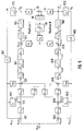
- the printing unit consists of a web offset machine from the four plate or blanket cylinders D1, D2, D3 and D4 (shown schematically) via bearings 40 on the fixed wall H (see FIG. 6) of the machine are rotatable. They each have an electric motor to turn them associated with a rotor package F and a stator package G.
- the stub axle 41 of the rotor F is immediate connected to the stub shaft 42 of the cylinder D; with others Words, both are so structurally integrated with each other, that they merge into one another while doing a drive connection form that about as rigid as a one-piece Steel shaft is.
- the on the free end faces of the electric motors F, G outstanding stub axles 43 are with sine / cosine absolute angular position encoders 44, provided.
- the electric motors F, G are designed as built-in motors. You can with three-phase servo motors in synchronous design with Permanent magnets can be executed. These are from one Power block 47 each controlled by digital current controller 48.
- the power block 47 is from an intermediate circuit supply 49 supplied with electrical energy.
- the digital current regulators 48 each communicate via interference-free optical fiber 50 with an axis peripheral module AP.
- the axis peripheral modules also have respective ones Interfaces 44a, 46a on the one hand for each of the at the Electric motors F, G attached angular position encoder 44 as well for one of the on the opposite shaft ends or Axle stub 45 on the free ends of cylinders D1 - D4 located angular position encoder 46.
- the axis I / O modules AP are from a common, digital signal processor 51 checked. This is as a drive controller for a maximum number of axes with position controller, Speed controller, motor control and encoder evaluation configurable.
- FIG 51 The respective internal structure of the signal processor is shown in FIG 51 and the axis peripheral modules AP enlarged shown and with abbreviations familiar to the expert referred to, so that there are further explanations in principle spare.
- SCC serial Communication control block
- FIG. 4 shows the integration of the drive system according to the invention 1 to 3 in a global concept for a multiple control with configurable, modular Control and regulation units illustrated.
- a master computer IPC-486 are blocks CPU-68-3 for programmable logic Control and setpoint generation intended.
- the signal processors 51 are connected to these coupled a system bus.
- the block diagram according to FIG. 5 represents an exemplary drive system according to the invention for two position-controlled axes I, II coupled via frictional slip (Schmitz rings). From a setpoint generation (for example according to FIG. 4), each axis I, II becomes angular position setpoints for their position control ⁇ sollI, ⁇ sollII specified. After comparison with the actual values ⁇ istI, ⁇ istII obtained via the angular position encoder 46 , the respective control difference is fed to a position controller K VI , K VII .
- each characteristic line element is connected on the input side to the output of the corresponding angular position sensor 46I, 46II.
- the respective outputs of proportional feedback elements K I, II , K II, I are also fed to the summing elements 53I, 53II, which cross- tap into the actual angular velocity ⁇ IstII or ⁇ IstI on the respective differentiating element 54II, 54I.
- the inputs of the differentiators 54I, 54II are each connected to the output of the corresponding angular position sensors 46I and 46II.
- This cross-coupling by means of the proportional elements K I, II or K II, I has a decoupling effect on the controlled systems / axes I or II which are coupled, for example, via the Schmitz rings.
- the respective outputs of the summing elements 53I and 53II open directly into respective proportional elements K -1 SI , K -1 SII , which represent factors relating, among other things, to the turning masses of the functional parts comprising the axes I, II.
- This is followed by current control circuits 55I, 55II, which convert the input current setpoints I sollI , I sollII into actual current values I istI , I istII .
- the current control loops 55I, 55II behave approximately to the outside like PT 2 elements known per se in control engineering.
- the respective actual current values I istI , I istII are supplied to proportional elements K TI , K TII , which represent the electric motor constant for converting current into a motor torque M MotI , M MotII .
- proportional elements K TI , K TII represent the electric motor constant for converting current into a motor torque M MotI , M MotII .
- the actual position of the angular position ⁇ istI , ⁇ istII can be determined in connection with the respective angular position transmitters 46I, 46II and the respective comparisons 58I, 58II at the input of the block diagram according to FIG. 5 to the target actual value - Make a comparison.
- the respective path velocities v I ' v II of the two rotating masses I, II are calculated according to a first or outer of the two pairs of proportional links R I or R II , which have the respective angular velocities ⁇ I, ⁇ II of the two rotating masses as an input variable.
- the web speeds V I , V II are subtracted from one another in the course of forming a difference 70.
- the slip s results from the quotient of this difference and one of the two circumferential path speeds V I , V II of the two rotating masses, as illustrated by the dividing element 59.
- the characteristic curve element 60 following this represents the specific friction characteristic when cylinder circumferential surfaces roll on one another and gives the coefficient of friction ⁇ R as a function value.
- the cylinder shaft E is axially extending Approach 62 provided by the electric motor G, F, N, Z projects coaxially and at the front end of the drive shaft rigidly and rigidly fixed and / or in one piece is executed.
- a pole or encoder wheel 63 of a hollow shaft encoder rigid or fixed in place This points radially on its outer edge projecting teeth 64, which according to the circumferential direction a certain division lined up are.
- On the outward facing end of the stator G, N comprising eccentric bushing B is a parallel to Fixed axis of rotation protruding mounting shaft 65, the at its free end the encoder head 66 of the hollow shaft encoder wearing.
- the distance 67 is such that on the one hand the operative connection of the encoder head and the Teeth 64 on the encoder wheel 63 can come about and on the other hand to a certain extent axial dislocations between the encoder head 66 and the encoder wheel 63 are possible without the functionality of this functional connection is impaired becomes.
- the encoder wheel 63 and / or its Teeth 64 are sufficiently wide. Also one central arrangement of the encoder head 66 with respect to the teeth is advantageous for this.
Abstract
Description
Die Erfindung betrifft ein elektrisches Antriebssystem zur Verstellung von einem oder mehreren dreh- und/oder verschwenkbaren Funktionsteilen von Geräten und Maschinen, insbesondere von Druckmaschinen, wozu mindestens ein Elektromotor verwendet wird, dessen Rotor zur steifen und direkten Verbindung mit dem Funktionsteil ausgebildet ist. Ferner betrifft die Erfindung die Anordnung eines mit einem geregelten Antriebssystem verbundenen Winkellagegebers, der einen dreh- oder schwenkbaren Fühlerrotor und ein diesem zugeordnetes, stationäres Abtastorgan aufweist, um die Winkellage eines an einer Wandung drehgelagerten und bezüglich seiner Drehachse längs-, schräg, quer- und/oder diagonal verstellbaren Funktionsteiles eines Gerätes oder einer Maschine zu bestimmen. Ferner betrifft die Erfindung eine Druckmaschine, insbesondere Offsetmaschine, die mit Direktantrieben ausgestattet ist.The invention relates to an electric drive system for Adjustment of one or more rotatable and / or pivotable Functional parts of devices and machines, especially of printing presses, including at least one electric motor is used, the rotor for stiff and direct Connection is formed with the functional part. Furthermore, the invention relates to the arrangement of a regulated drive system connected angular position encoder, the a rotating or swiveling sensor rotor and one assigned, stationary scanning member to the angular position one rotatably mounted on a wall and with respect its axis of rotation longitudinally, obliquely, transversely and / or diagonally adjustable functional part of a device or a machine to determine. The invention further relates to a Printing machine, in particular offset machine, with direct drives Is provided.
Antriebssysteme, Antriebsanordnungen bzw. -verfahren und Druckmaschinen etwa dieser Art sind aus der DE-OS 41 38 479 und der älteren EP-Patentanmeldung 93 106 554.2 bekannt. Diese Fundstellen werden hiermit zum Bestandteil der vorliegenden Offenbarung gemacht.Drive systems, drive arrangements and procedures and Printing machines of this type are from DE-OS 41 38 479 and the older EP patent application 93 106 554.2. These sites are hereby part of the present disclosure made.
Nach dem sonstigen Stand der Technik sind die einzelnen Funktionseinheiten von Druckmaschinen, beispielsweise Abrollung/Rollenwechsler, Druckwerke, Druckzylinder, Trockner mit Kühlwalzen, Falzer, Querschneider, Ablage usw. durch mechanische Wellen und/oder Zahnräder miteinander verkoppelt, um deren gegenseitige Winkellageorientierung herbeizuführen. Will man diese Funktionsteile bzw. -komponenten vereinzeln und auf die mechanische Verkopplung verzichten, so sind die einzelnen Funktionsteile mit eigenen Antriebssystemen auszurüsten, die nach der genannten DE-OS 41 38 479 als Direktantriebe ausgeführt sind. Zur Erzielung der notwendigen Winkellageorientierung der einzelnen Druckmaschinen-Komponenten untereinander ist eine entsprechende Synchronisation der Antriebssysteme erforderlich.According to the other state of the art, the individual Functional units of printing machines, for example unwinding / reel changers, Printing units, printing cylinders, dryers with chill rolls, folder, sheeter, tray, etc. mechanical shafts and / or gears coupled together, to bring about their mutual angular orientation. If you want these functional parts or components separate and do without mechanical coupling, so are the individual functional parts with their own drive systems equip, according to the DE-OS 41 38 479 are designed as direct drives. To achieve the necessary orientation of the individual printing press components among them is a corresponding one Synchronization of the drive systems required.
Zur Lösung der aufgezeigten Problematik werden bei einem elektrischen Antriebssystem mit den eingangs genannten Merkmalen erfindungsgemäß ein oder mehrere Winkellagegeber, die Winkelbewegungen des Elektromotor-Rotors und/oder Funktionsteiles der Maschine oder des Gerätes aufnehmen, ein Signalverarbeitungsmodul, das eingangsseitig zur Aufnahme der Winkellagesignale als Istwerte mit dem oder den Winkelgebern verbunden sowie zur Aufnahme von Sollwerten und zu deren Vergleich mit den Istwerten ausgebildet ist, und ein vom Signalverarbeitungsmodul kontrollierter Leistungsverstärker angeordnet, der ausgangsseitig mit dem Elektromotor zu dessen Ansteuerung verbunden ist.To solve the problems outlined at one electric drive system with the aforementioned According to the invention, one or more angular position sensors, the angular movements of the electric motor rotor and / or functional part machine or device Signal processing module, the input side for recording the angular position signals as actual values with the angular encoder (s) connected and for recording setpoints and whose comparison is made with the actual values, and a Power amplifier controlled by the signal processing module arranged, the output side with the electric motor is connected to its control.
Dabei bildet das Signalverarbeitungsmodul einen konfigurierbaren und parametrierbaren Antriebsregler, mit dem auch komplexe Regel-Algorithmen und/oder mehrere Regelkreise realisiert werden können. Mit der Erfindung ist ein Konzept für eine Vielfachsteuerung einer Mehrzahl von Drehachsen geschaffen, wobei sich das zugehörige Steuerungs- und Regelungssystem modular projektieren läßt. Beim besonderen Anwendungsfall in Druck-, insbesondere Offsetmaschinen, ist das erfindungsgemäße Antriebssystem besonders geeignet, weil damit eine hohe Qualität bzw. Genauigkeit der Winkellageorientierung, wie z. B. zwischen den Druckeinheiten, wo die Rasterpunkte verschiedener Farben in einem engen Toleranzbereich gedruckt werden müssen, erreichbar ist.The signal processing module forms a configurable one and parameterizable drive controller, with which too complex control algorithms and / or several control loops implemented can be. With the invention is a concept for multiple control of a plurality of rotary axes created, with the associated control and regulation system can be configured modularly. For a special application in printing, in particular offset machines the drive system according to the invention is particularly suitable, because this ensures high quality and accuracy of the angular orientation, such as B. between the printing units where the halftone dots of different colors within a narrow tolerance range must be printed is available.
Nach einer baulichen Konkretisierung des erfindungsgemäßen Antriebssystems ist der Rotor des Elektromotors mit dem Funktionsteil, z. B. Druckzylinder, baulich integriert und/oder einstückig ausgeführt. Einerseits kann dies durch Anbau des Rotors an einem Wellenstummel des drehbaren Funktionsteiles erfolgen. Zum anderen kann es vorteilhaft sein, den im erfindungsgemäßen Antriebssystem eingesetzten Elektromotor mit einem walzen- oder zylinderförmigen Außenläufer oder -rotor auszubilden. Damit ist erreicht, daß die Form des Rotors etwa der zweckmäßig rotationssymmetrischen Form des Funktionsteiles entspricht, und insbesondere darin baulich aufgenommen sein kann.After a structural specification of the invention The drive system is the rotor of the electric motor with the Functional part, e.g. B. pressure cylinder, structurally integrated and / or made in one piece. On the one hand, this can be done by Attachment of the rotor to a stub shaft of the rotatable functional part respectively. On the other hand, it can be advantageous the electric motor used in the drive system according to the invention with a cylindrical or cylindrical external rotor to train or rotor. This ensures that the The shape of the rotor, for example, is expediently rotationally symmetrical Form of the functional part corresponds, and in particular therein can be structurally included.
Analog dem genannten Direktantrieb des Funktionsteiles liegt im Rahmen der Erfindung eine Direktmessung von dessen Winkellage, -geschwindigkeit, -beschleunigung usw. So ist nach einer vorteilhaften Ausbildung der Erfindung der Winkellagegeber direkt am Funktionsteil zur unmittelbaren Messung von dessen Winkel- bzw. Dreh/Schwenkbewegungen angebracht. Vor allem im Zusammenhang mit hochauflösenden, schnellen Winkellagegebern, wie an sich bekannt, kann so eine unmittelbare und mithin äußerst wirklichkeitsgetreue Beobachtung der Regelstrecke, nämlich des zu drehenden oder schwenkenden Funktionsteiles, durchgeführt werden.Analogous to the direct drive of the functional part mentioned lies within the scope of the invention a direct measurement of it Angular position, speed, acceleration etc. So it is according to an advantageous embodiment of the invention, the angular position encoder directly on the functional part for immediate measurement attached by its angular or rotary / pivoting movements. Especially in connection with high-resolution, Fast angular position encoders, as known per se, can do so an immediate and therefore extremely realistic Observation of the controlled system, namely the one to be rotated or pivoting functional part.
Nach einer alternativen Ausbildung ist dem Elektromotor ein einziger Winkellagegeber zugeordnet, der die Winkelbewegungen des Rotors des Elektromotors aufnimmt; gleichzeitig ist ein in der Regelungstechnik an sich bekanntes Beobachtermodul für Zustandsgrößen des Funktionsteiles eingerichtet, das vorzugsweise in Differenzsignalaufschaltung (in der Regelungstechnik an sich bekannt) mit dem Winkellagegeber und/oder dem Signalverarbeitungsmodul gekoppelt ist. Die Differenzsignalaufschaltung läßt sich auf der Basis der Erfindung auch im Zusammenhang mit wenigstens zwei Winkellagegebern einsetzen, die je am Rotor des Elektromotors und am Funktionsteil zur unmittelbaren Aufnahme von deren Winkelbewegungen angebracht sind.According to an alternative training, the electric motor is on assigned only angular position encoder, the angular movements the rotor of the electric motor; is at the same time an observer module known per se in control engineering set up for state variables of the functional part, preferably in differential signal connection (in the control technology known per se) with the angular position encoder and / or the signal processing module is coupled. The differential signal feed can be based on the Invention also in connection with at least two angular position sensors insert, each on the rotor of the electric motor and on the functional part for the immediate inclusion of their Angular movements are appropriate.
Für die Zwecke der Erfindung kommen höchstauflösende, schnelle Winkellagegeber, beispielsweise in der Ausführung als Sinus/Kosinus-Absolutgeber, als Inkrementalgeber mit Rechtecksignalen und Nullimpulssignal und als Inkrementalgeber mit Sinus/Kosinus-Signal nebst Nullimpulssignal in Frage. Um im Betrieb axiale Verstellungen des Funktionsteiles, bei Druckmaschinen beispielsweise die sogenannte Seitenregisterverstellung, zuzulassen, sind als Winkellagegeber im Sinne der Erfindung vor allem Hohlwellengeber mit eine (Zahn-) Teilung aufweisendem Geberrad und einem Geberkopf geeignet. Diese sind über einen Luftspalt voneinander radial beabstandet, und axiale Versetzungen gegeneinander innerhalb eines bestimmten Rahmens beeinträchtigen die Abtastfunktion des Geberkopfes gegenüber dem Geberrad nicht. Der mit dem Einsatz des Hohlwellengebers erzielte Vorteil besteht vor allem darin, daß das Geberrad mit dem (abzutastenden) Funktionsteil baulich integriert und/oder einstückig ausgeführt sein kann, so daß aufgrund dieser Direktverbindung eine unmittelbare Beobachtung bzw. Erfassung von dessen Winkelbewegungen gewährleistet ist.For the purposes of the invention, high-resolution, Fast angular position encoder, for example in the version as a sine / cosine absolute encoder, as an incremental encoder with Square wave and zero pulse signal and as an incremental encoder with sine / cosine signal and zero pulse signal in Question. To make axial adjustments of the functional part during operation, in printing machines, for example, the so-called page register adjustment, are to be approved as angular position sensors in the sense of the invention especially with hollow shaft encoder a (tooth) pitch sensor wheel and a sensor head suitable. These are separated from each other by an air gap radially spaced, and axial displacements against each other within a certain frame affect the scanning function of the encoder head compared to the encoder wheel. The advantage achieved with the use of the hollow shaft encoder consists mainly in the fact that the encoder wheel with the Functional part (to be scanned) structurally integrated and / or can be made in one piece, so that due to this Direct connection an immediate observation or Detection of its angular movements is guaranteed.
Mit Vorteil werden beim erfindungsgemäßen Antriebssystem reaktionsschnelle Leistungsverstärker mit digitalen Phasenstromreglern verwendet. Der Umrichter kann dabei mit Spannungszwischenkreis oder mit Direkteinspeisung und damit hoher Zwischenkreisspannung ausgeführt sein (wie an sich bekannt). Mit letzterer wird eine große zeitliche Stromänderung ermöglich. Die digitale Phasenstromregelung ist für das erfindungsgemäße Antriebssystem zweckmäßig mit Pulsbreitenmodulation hoher Taktfrequenz, schnellen Transistorschaltern und Spannungsvorsteuerung ausgeführt, wobei die Phasenstromsollwerte und/oder die Vorsteuerwerte über störsichere Lichtwellenleiter-Verbindungen vorgegeben werden. Ferner ist eine Rückmeldung der Phasenstromistwerte und/oder -spannungen zur Motorführung sowie eine Vorgabe von Werten zur Konfigurierung und Parametrierung nebst Rückmeldung von Statusinformationen zur Diagnose vorteilhaft.The drive system according to the invention is advantageous responsive power amplifiers with digital phase current regulators used. The converter can use a DC link or with direct feed and thus higher DC link voltage must be executed (as known per se). With the latter there will be a large temporal change in current enabled. The digital phase current control is for the drive system according to the invention expediently with pulse width modulation high clock frequency, fast transistor switches and voltage pre-control, the Phase current setpoints and / or the pilot values via interference-free Optical fiber connections can be specified. There is also feedback of the actual phase current values and / or voltages for motor control and a specification of values for configuration and parameterization along with Feedback of status information for diagnosis is advantageous.
Damit für die Kontrolle der Schwenk- oder Drehbewegungen des Funktionsteiles eine hohe Dynamik gewährleistet ist, empfiehlt sich für das erfindungsgemäße Antriebssystem der Einsatz schneller Signalverarbeitung. Diese ist zweckmäßig strukturiert in einen digitalen Signalprozessor und einen damit gekoppelten, separat ausgeführten Achsperipheriemodul. Der Signalprozessor ist als konfigurierbarer und parametrierbarer Antriebsregler mit realisierbaren Abtastzeiten um 100µsec. (auch bei komplexen Regel-Algorithmen und mehreren Regelkreisen) sowie bei Rechenlaufzeiten im Bereich von 50µsec. erhältlich. Die Funktionen des Signalprozessors können die Geberauswertung, die Motorführung, Drehzahlregelung, Winkellageregelung, Feininterpolation der Vorgabewerte und anderes umfassen. Das Achsperipheriemodul ist zweckmäßig mit einer über Lichtwellenleiter laufenden Schnittstelle zu den digitalen Phasenstromreglern und ferner mit einer Schnittstelle zu den Winkellagegebern vorzugsweise in der Ausführung als Sinus/Kosinus-Absolutgeber, als Inkrementalgeber mit Rechtecksignalen und Nullimpulssignal und als Inkrementalgeber mit Sinus/Kosinus-Signal mit Nullimpulssignalen versehen.So for the control of the swiveling or rotating movements a high dynamic of the functional part is guaranteed, is recommended for the drive system according to the invention Use of fast signal processing. This is useful structured into a digital signal processor and one coupled, separately designed axis peripheral module. The signal processor is configurable and parameterizable Drive controller with realizable sampling times around 100µsec. (even with complex control algorithms and several Control loops) and computing times in the area of 50µsec. available. The functions of the signal processor can the encoder evaluation, the motor control, Speed control, angular position control, fine interpolation of the Include default values and other. The axis peripheral module is useful with a fiber optic cable Interface to the digital phase current controllers and also with an interface to the angular position encoder preferably as a sine / cosine absolute encoder, as an incremental encoder with square wave signals and Zero pulse signal and as an incremental encoder Provide sine / cosine signal with zero pulse signals.
Durch diese Struktur für das erfindungsgemäß eingesetzte Signalverarbeitungsmodul läßt sich durch simultane Vorgabe der Sollwerte entsprechend dem Prinzip der Lagesteuerung ein winkellageorientierter Betrieb für die relevanten Drehmassen bzw. einzelne Funktionsteile eines Gerätes oder einer Maschine, insbesondere Druckmaschine, realisieren. Dabei können im Signalverarbeitungsmodul die Sollwerte unter Beachtung der Begrenzungen im Ruck, in der Beschleunigung, in der Geschwindigkeit generiert werden. Es läßt sich insbesondere eine Aufschaltung bzw. Vorsteuerung der Winkellage-Geschwindigkeit, -beschleunigung und des -rucks herbeiführen.Through this structure for the used according to the invention Signal processing module can be set by simultaneous specification the setpoints according to the principle of position control an angular position oriented operation for the relevant turning masses or individual functional parts of a device or one Realize machine, especially printing machine. Here can setpoints in the signal processing module Observing the limitations in jerk, in acceleration, generated in speed. It can be particularly activation or precontrol of the angular position speed, - Accelerate and accelerate.
Reiben mehrere Funktionsteile bei ihrer Drehung aufeinander, stellen sie über Reibschlupf verkoppelte Drehmassen dar. Bei Druckmaschinen-Zylinder bezeichnet man aufeinanderreibende, blanke Mantelabschnitte, die wegen Druck aufeinanderliegen, als sogenannte Schmitz-Ringe. Dem Problem der über Reibschlupf verkoppelten Drehmassen wird durch eine besondere Ausbildung der Erfindung begegnet, nach der das Signalverarbeitungsmodul mehrere, je einem Funktionsteil zugeordnete Regler oder Reihen mit mehreren Regelgliedern aufweist, die miteinander über zusätzliche, gewichtete Rückführungen verkoppelt sind. Zweckmäßig ist eine Kreuzverkopplung realisiert.If several functional parts rub against each other during their rotation, provide coupled rotating masses via friction slip With printing press cylinders one calls bare jacket sections rubbing against each other because of Pressure lie on one another as so-called Schmitz rings. The Problem of the rotating masses coupled via friction slip countered by a special training of the invention, after which the signal processing module several, one each Function part assigned controllers or rows with several Has control elements that interact with each other via additional weighted returns are coupled. Is expedient cross coupling realized.
Beim Anwendungsfall "Druckmaschinen" tritt bei den rotierenden Druckzylindern als Störgröße der an sich bekannte "Kanalschlag" auf, der auf eine Längsrille im Zylinder zum Aufziehen eines Gummituchs oder einer Druckplatte beruht. Die an der Manteloberfläche zu Tage tretende Rille führt zu einer sich ändernden Normalkraft und damit zu einem sich ändernden Drehmoment. Diesem Phänomen des "Kanalschlags" läßt sich im Rahmen des erfindungsgemäßen Antriebssystems zweckmäßig durch Bewertung der Istwerte mit Kennliniengliedern und Störgrößenaufschaltung begegnen.In the application case "printing presses" occurs with the rotating Printing cylinders as a disturbance variable known per se "Channel blow" on a longitudinal groove in the cylinder to Pulling a blanket or a printing plate based. The groove emerging on the surface of the jacket leads to a changing normal force and thus one changing torque. This phenomenon of "channel shock" can be used in the drive system according to the invention expediently by evaluating the actual values with characteristic elements counteracting feedforward control.
Aus der eingangs erläuterten Problematik wird ferner das der Erfindung zugrundeliegende Problem aufgeworfen, eine Beobachterstruktur und -methodik zu schaffen, mit der eine möglichst verlustlose und naturgetreue Messung bzw. Wiedergabe des Dreh- und/oder Schwenkverhaltens von Funktionsteilen möglich ist. Insbesondere soll eine maximale Kraftschlüssigkeit zwischen einem sich mitdrehenden Winkellagegeber und der davon beobachteten Drehmasse herrschen. Zur Lösung wird bei einer Anordnung eines Winkellagegebers mit den gattungsgemäßen Merkmalen vorgeschlagen, daß vom Winkellagegeber dessen Fühlerrotor mit dem Funktionsteil unmittelbar steif und starr verbunden, und das Abtastorgan an der Wandung abgestützt sind, wobei eine auf das Abtastorgan einwirkende Nachführeinrichtung dergestalt ausgebildet und angeordnet ist, daß es die Verstellbewegungen des Funktionsteiles mit dem Fühlerrotor entsprechend nachvollzieht. Damit können vorteilhaft Funktionsteil-Verstellbewegungen größeren Umfangs, für die sich der Luftspalt zwischen dem Abtastorgan und dem Fühlerrotor nicht ausreichend bemessen läßt, ausgeglichen werden. Nach der Erfindung wirkt nämlich die Nachführeinrichtung so auf das Abtastorgan des Winkellagegebers ein, daß das Abtastorgan die Funktionsteil (Drehmasse)/Fühlerrotor-Verstellbewegungen, jedenfalls solange diese die Abmessungen des Luftspaltes zwischen Abtastorgan und Fühlerrotor überschreiten, nachvollzieht. Die Nachführeinrichtung kann mehrere Funktionskomponenten umfassen: eine in Achsrichtung des Fühlerrotors gegebenenfalls einschließlich des Motors/Funktionsteils gerichtete Linearführung, um beim Anwendungsfall "Druckmaschinen" das Abtastorgan an Seitenregister-Verstellungen des Zylinders als Funktionsteil anzupassen; eine bezüglich der genannten Achse radial auslenkende Exzenterführung, um beim Anwendungsfall "Druckmaschinen" das Abtastorgan auf Anstellbewegungen oder Diagonalregister-Verstellungen des Druckzylinders einzustellen, die - wie an sich bekannt - mittels exzentrischer Auslenkung der Zylinder/Motor-Drehachse herbeigeführt werden. Dabei erscheint es notwendig, daß die Funktionsteil-/Fühlerrotor- und andererseits die Abtastorgan-Exzenterführungen einander entsprechend, insbesondere zueinander kongruent, ausgebildet sind, um die Nachführung vor allem in Form sich deckender, exzentrischer Umlaufbahnen von Abtastorgan und Funktionsteil/Fühlerrotor zu gewährleisten. Die Genauigkeit der Nachführung läßt sich noch dadurch fördern, daß beide Exzenterführungen durch eine gemeinsame, lösbare, vorzugsweise mechanische Verbindungseinrichtung miteinander gekoppelt und/oder synchronisiert sind.The problem described at the beginning also becomes the problem underlying the invention raised a To create an observer structure and methodology with which one lossless and lifelike measurement or reproduction as possible the turning and / or swiveling behavior of functional parts is possible. In particular, there should be maximum frictional engagement between a rotating one Angular position encoder and the rotating mass observed from it to rule. The solution to an arrangement is a Angular position encoder with the generic features proposed that the angular position sensor rotor with the functional part immediately stiff and rigid connected, and the sensing element supported on the wall are, one acting on the sensing element Tracking device designed and arranged in such a way is that it has the adjustment movements of the functional part the sensor rotor accordingly. So that can advantageous functional part adjustment movements larger Circumference, for which the air gap between the Sufficiently dimensioned sensing element and the sensor rotor lets be balanced. After the invention works namely the tracking device on the scanning element of the angular position encoder a that the sensing element the functional part (Rotating mass) / sensor rotor adjustment movements, at least as long these are the dimensions of the air gap between the sensing element and exceed the sensor rotor, understand. The Tracking device can include several functional components: one in the axial direction of the sensor rotor if necessary including the motor / functional part Linear guide to the "printing press" application Scanning device on side register adjustments of the cylinder adapt as a functional part; one related to the above Radially deflecting eccentric guide axis for use in applications "Printing machines" the scanning element on positioning movements or diagonal register adjustments of the printing cylinder adjust, which - as known per se - by means of eccentric Deflection of the cylinder / engine axis of rotation brought about become. It seems necessary that the functional part / sensor rotor and on the other hand the scanning organ eccentric guides corresponding to each other, especially to each other congruent, trained to track especially in the form of overlapping, eccentric orbits of sensing element and functional part / sensor rotor. The accuracy of the tracking can still be promote that both eccentric guides by a common, Detachable, preferably mechanical connection device coupled and / or synchronized with each other are.
Um eine stationäre, steife Abstützung des Abtastorgans an dem Maschinenfundament, insbesondere Wandung einer Druckmaschine, zu erreichen, ist in weiterer Ausbildung der Erfindung eine Feststelleinrichtung vorgesehen, die mit der Nachführeinrichtung derart verbunden, insbesondere synchronisiert ist, daß sie nach Beendigung der aktiven Nachführung des Abtastorgans dieses relativ zur Wandung fixiert.For a stationary, rigid support of the scanning element the machine foundation, in particular the wall of a printing press, To achieve is in a further embodiment of the invention a locking device provided with the Tracking device connected in this way, in particular synchronized is that after active tracking has ended the sensing element fixed this relative to the wall.
Zur axialen Linearverschiebung oder exzentrischen Auslenkung des Stators entsprechend den Funktionsteil/Fühlerrotor-Verstellbewegungen ist es zweckmäßig, eine oder mehrere, gesonderte Bewegungseinrichtungen vorzusehen: zum Beispiel einen an einer Exzenterbuchse, an die das Abtastorgan fixiert ist, angreifenden Drehantrieb oder einen Linearantrieb, der am axial verschiebbar gelagerten Abtastorgan angreift, um jeweils das Abtastorgan zur Beibehaltung eines ausreichenden Luftspalts gegenüber dem Fühlerrotor nachzuführen. Diese Nachführbewegungen lassen sich in ihrer Genauigkeit noch weiter verbessern, indem die genannten Dreh- oder Linearantriebe, die jeweils dem Abtastorgan einerseits und dem Drehmassen-/Fühlerrotor-Verbund andererseits zugeordnet sind, bei Registerverstellung oder Anstellbewegung (Einsatzfall: Druckmaschinen) miteinander gekoppelt und/oder synchronisiert sind.For axial linear displacement or eccentric deflection of the stator according to the functional part / sensor rotor adjustment movements it is useful to have one or to provide several, separate movement devices: for example one on an eccentric bush to which the scanning element is fixed, attacking rotary drive or a Linear drive, on the axially displaceable scanning element attacks each to maintain the sensing element a sufficient air gap compared to the sensor rotor track. These tracking movements can be in improve their accuracy even further by the above Rotary or linear drives, each of the sensing element on the one hand and the rotating mass / sensor rotor assembly on the other are assigned, when changing the register or adjusting movement (Use case: printing presses) coupled with each other and / or are synchronized.
Im Hinblick auf die eingangs erwartete Problematik wird bei Druckmaschinen das der Erfindung zugrundeliegende Problem aufgeworfen, deren dreh- oder schwenkbare Funktionsteile zuverlässig beobachten und entsprechende Zustandsgrößen einem geregelten Antriebssystem zuführen zu können. Dabei sollen Verfälschungen des Meßergebnisses möglichst ausgeschlossen bzw. eine möglichst verlustlose Kopplung mit maximaler Kraftschlüssigkeit in Kraft- bzw. Drehmomentübertragungsrichtung zwischen den anzutreibenden Zylindern und dem Meßwertgeber ermöglicht sein. Zur Lösung wird bei einer gattungsgemäßen Druckmaschine erfindungsgemäß vorgeschlagen, daß die Zylinder zur unmittelbaren Messung ihrer Winkelgrößen mit je einem Winkellagegeber direkt verbunden sind, der ausgangsseitig an das Antriebssystem angeschlossen ist. Der Winkellagegeber bildet damit einen Direkt-Beobachter für das Funktionsteil im Rahmen einer Antriebs-Steuerungskette oder eines Antriebs-Regelkreises, der insbesondere die Umfangsregisterverstellung herbeiführt. Mit dieser Direktbeobachtung kann für jedes Funktionsteil, nämlich Zylinder- bzw. Druckwerkswalze, ein spielfreier, trägheitsarmer und mechanisch steifer Meßstrang bzw. Meßkette aufgebaut werden. Dies ergibt eine hohe Regelgenauigkeit und -dynamik, so daß sich exakte Bahnführung, konstante Bahnspannung und gleichbleibende Farbgebung über die so ermöglichte, hochpräzise Registersteuerung und Druckanstellung erreichen lassen. Die relevanten Drehmassen (beispielsweise Platten- und Gummituch-Zylinder in einem Druckwerk) werden erfindungsgemäß direkt, ohne dazwischen angeordnete Feder-, Dämpfungs-, Reibungsglieder usw., erfaßt, so daß unter Ausschluß von Elastizitäten, Nachgiebigkeiten und Spielen das Bewegungsverhalten des in der Druckmaschine zu beobachtendem Funktionsteiles originalgetreu im Regelungssystem weitergegeben werden kann. Dabei ist es zweckmäßig, auch das Abtastorgan des Winkellagegebers an einer stationären Wandung, beispielsweise der Druckmaschinenwand, elastizitäts- und spielfrei zu fixieren.With regard to the problem initially expected, Printing machines the problem underlying the invention thrown up, their rotating or swiveling functional parts reliably observe and appropriate state variables one controlled drive system. Here falsifications of the measurement result should be avoided as far as possible or a lossless coupling with maximum Non-positive in the direction of force or torque transmission between the cylinders to be driven and be made possible for the transmitter. The solution is at one Generic printing machine proposed according to the invention, that the cylinders for immediate measurement of their angular sizes directly connected to an angular position encoder are connected to the drive system on the output side is. The angular position encoder thus forms a direct observer for the functional part as part of a drive control chain or a drive control loop, in particular causes the circumferential register adjustment. With this direct observation can for each functional part, namely Cylinder or printing unit roller, a backlash-free, low inertia and mechanically rigid measuring string or measuring chain being constructed. This results in high control accuracy and dynamics, so that there is exact path guidance, constant Web tension and consistent coloring via the thus made possible high-precision register control and pressure adjustment let achieve. The relevant turning masses (for example, plate and blanket cylinders in one Printing unit) are directly according to the invention, without in between arranged spring, damping, friction members, etc., detected, so that to the exclusion of elasticity, compliance and play the movement behavior of the in the printing press Functional part to be observed true to the original in Regulatory system can be passed. It is expedient, also the scanning element of the angular position encoder a stationary wall, for example the press wall, to fix without elasticity and play.
In Weiterführung dieses Gedankens ergibt sich die Notwendigkeit, daß der an einem Druckzylinder beispielsweise steif und dicht angesetzte Fühlerrotor zur Realisierung von Druck-An- und Druck-Ab-Bewegungen sowie Diagonalregister-Verstellungen exzentrisch auslenkbar sind. Dem wird mit einer vorteilhaften Ausbildung der Erfindung Rechnung getragen, wonach beim Winkellagegeber Fühlerrotor und Abtastorgan zueinander mit einem solchen Abstand angeordnet und/oder derart verstellbar ausgebildet sind, daß der von diesem begrenzte Luftspalt sich ausreichend verändern und dabei entsprechende, exzentrische Auslenkungen auffangen kann.Continuing with this idea, the necessity arises that on a printing cylinder for example stiff and tightly attached sensor rotor for the realization of Push-up and push-down movements as well as diagonal register adjustments are eccentrically deflectable. That will be with one taken into account advantageous embodiment of the invention, after which with the angular position sensor, sensor rotor and scanning element arranged at such a distance from each other and / or are so adjustable that the of this limited air gap change sufficiently and absorb corresponding, eccentric deflections can.
So können Stellbewegungen des steifen Drehmasse(Funktionsteil)/Fühlrotor-Verbunds ausgeglichen werden, obgleich das Abtastorgan an der stationären Wandung ortsfest fixiert ist. Ein zwischen dem Abtastorgan und dem Fühlrotor in der Regel vorhandener Luftspalt wird hierzu ausgenutzt. Diese Erfindungsausbildung läßt sich praktisch durch einen Hohlwellengeber realisieren, bei dem der das Geberrad bildende Fühlrotor dem Abtastorgan gegenüberliegend angeordnet ist, ohne mit letzterem über Lager oder dergleichen mechanisch verbunden zu sein.This allows adjustment movements of the rigid rotating mass (functional part) / sensor rotor assembly be balanced although the sensing element on the stationary wall is fixed in place. One between the sensing element and the The sensor rotor usually has an air gap exploited. This invention training can be practical realized by a hollow shaft encoder, in which the Sensor rotor forming the sensor wheel opposite the sensing element is arranged without bearing with the latter or the like to be mechanically connected.
Weitere Merkmale, Einzelheiten und Vorteile auf der Basis der Erfindung ergeben sich aus den Unteransprüchen und der nachfolgenden Beschreibung bevorzugter Ausführungsbeispiele der Erfindung. Diese zeigen in:
- Fig. 1
- das Schema eines erfindungsgemäßen Direkt-Antriebsystems teilweise in Längsansicht,
- Fig. 2
- im teilweisen Längsschnitt einen mit einem zu drehenden Zylinder gekoppelten Direktantrieb,
- Fig. 3
- ein Blockschaltbild eines Signalverarbeitungsmoduls des erfindungsgemäßen Direktantriebs,
- Fig. 4
- ein Blockschaltbild eines erfindungsgemäßen, modularen Antriebssystems zur Steuerung und Regelung einer Mehrzahl von Funktionsteile-Achsen,
- Fig. 5
- das dynamische Verhalten eines Ausführungsbeispiels der Erfindung anhand eines Strukturblockschemas,
- Fig. 6
- im axialen bzw. Längsschnitt die Anbringung eines Hohlwellengebers am Direktantrieb bzw. der Wandung eines Druckwerkszylinder,
- Fig.7
- eine Richtungspfeil VII in Fig. 6 entsprechende Stirnansicht und
- Fig. 8
- eine Richtungspfeil VIII in Figur 7 entsprechende Stirnansicht.
- Fig. 1
- the diagram of a direct drive system according to the invention partly in longitudinal view,
- Fig. 2
- in partial longitudinal section a direct drive coupled to a cylinder to be rotated,
- Fig. 3
- 2 shows a block diagram of a signal processing module of the direct drive according to the invention,
- Fig. 4
- 1 shows a block diagram of a modular drive system according to the invention for controlling and regulating a plurality of functional part axes,
- Fig. 5
- the dynamic behavior of an exemplary embodiment of the invention on the basis of a structure block diagram,
- Fig. 6
- in the axial or longitudinal section the attachment of a hollow shaft encoder to the direct drive or the wall of a printing unit cylinder,
- Fig. 7
- a directional arrow VII in Fig. 6 corresponding front view and
- Fig. 8
- a directional arrow VIII in Figure 7 corresponding end view.
Gemäß Figur 1 besteht das Druckwerk einer Rollenoffset-Maschine
aus den vier Platten- bzw. Gummituchzylindern D1,
D2, D3 und D4 (schematisch dargestellt), die über Lager 40
an der ortsfesten Wandung H (vgl. Figur 6) der Maschine
drehbar sind. Zu ihrer Drehung ist ihnen Jeweils ein Elektromotor
mit einem Rotorpaket F und einem Statorpaket G zugeordnet.
Der Achsstummel 41 des Rotors F ist unmittelbar
mit dem Achsstummel 42 des Zylinders D verbunden; mit anderen
Worten, beide sind miteinander so baulich integriert,
daß sie ineinander übergehen und dabei eine Antriebsverbindung
bilden, die etwa so drehsteif wie eine einstückige
Stahlwelle ist. Die an den freien Stirnseiten der Elektromotoren
F,G herausragenden Achsstummel 43 sind mit Sinus/Kosinus-Absolut-Winkellagegebern
44, versehen. Am entgegengesetzten
Ende stehen Achsstummel 45 von den Zylindern
D1 - D4 vor, die ebenfalls je mit einem gleichartigen Absolut-Winkellagegeber
46 versehen sind. Die Elektromotoren
F,G sind konstruktiv als Einbaumotoren ausgeführt. Sie können
mit Drehstrom-Servomotoren in synchroner Bauart mit
Permanentmagneten ausgeführt sein. Diese werden von einem
Leistungsblock 47 jeweils mit digitalem Stromregler 48 angesteuert.
Der Leistungsblock 47 wird von einer Zwischenkreis-Versorgung
49 aus mit elektrischer Energie versorgt.
Die digitalen Stromregler 48 kommunizieren jeweils über
störsichere Lichtwellenleiter 50 mit einem Achs-Peripheriemodul
AP. Die Achs-Peripheriemodule weisen ferner jeweilige
Schnittstellen 44a, 46a einerseits für je einen der an den
Elektromotoren F,G angebrachten Winkellagegeber 44 als auch
für je einen der auf den entgegengesetzten Wellenenden bzw.
Achsstummeln 45 an den freien Stirnseiten der Zylinder D1 -
D4 befindlichen Winkellagergeber 46 auf. Die Achs-Peripheriemodule
AP werden von einem gemeinsamen, digitalen Signal-Prozessor
51 kontrolliert. Dieser ist als Antriebsregler
für eine maximale Anzahl von Achsen mit Lageregler,
Drehzahlregler, Motorführung und Geberauswertung konfigurierbar.According to FIG. 1, the printing unit consists of a web offset machine
from the four plate or blanket cylinders D1,
D2, D3 and D4 (shown schematically) via
In Figur 3 ist die jeweilige interne Struktur des Signal-Prozessors 51 als auch der Achs-Peripheriemodule AP vergrößert dargestellt und mit dem Fachmann geläufigen Abkürzungen bezeichnet, so daß sich weitere Erläuterungen grundsätzlich erübrigen. Mit SCC ist ein sogenannter serieller Kommunikations-Steuerbaustein bezeichnet.The respective internal structure of the signal processor is shown in FIG 51 and the axis peripheral modules AP enlarged shown and with abbreviations familiar to the expert referred to, so that there are further explanations in principle spare. With SCC is a so-called serial Communication control block called.
In Figur 4 ist die Einbindung des erfindungsgemäßen Antriebssystems
gemäß Figur 1 - 3 in ein globales Konzept für
eine Vielfachsteuerung mit projektierbaren, modularen
Steuerungs- und Regelungseinheiten veranschaulicht. Neben
einem Leitrechner IPC-486 sind Bausteine CPU-68-3 zur speicherprogrammierbaren
Steuerung und zur Sollwertgenerierung
vorgesehen. An diese sind die Signalprozessoren 51 über
einen Systembus angekoppelt.FIG. 4 shows the integration of the drive system according to the
Das Blockschema gemäß Figur 5 stellt ein beispielhaftes,
erfindungsgemäßes Antriebssystem für zwei über Reibschlupf
(Schmitz-Ringe) verkoppelte, lagegeregelte Achsen I, II
dar. Aus einer Sollwert-Generierung (beispielsweise gemäß
Figur 4) werden Jeder Achse I, II zu ihrer Lagesteuerung
Winkellagesollwerte sollI, sollII vorgegeben. Nach
Vergleich mit dem über die Winkellagegeber 46 jeweils
erhaltenen Istwerten istI, istII wird die jeweilige
Regeldifferenz einem Lageregler KVI, KVII zugeführt. Dessen
jeweiliger Ausgangswert wird einer Differenzbildung 52I,
52II mit dem differenzierten Winkellage-Istwert, d.h. der
jeweiligen Ist-Winkelgeschwindigkeit ΩistI, ΩIstII der
Achsen I, II unterworfen. Der daraus jeweils resultierende
Differenzwert wird einem Drehzahlregler KpI, KpII zugführt,
dessen jeweiliger Ausgang auf ein Summierglied 53I, 53II
trifft. Jedem dieser Summierglieder 53I, 53II ist zur
Bildung einer Störgrößenaufschaltung der Ausgang eines
Kennliniengliedes f(I), f(II) als Funktion der Winkellage
I, II zugeführt. Demgemäß ist jedes Kennlinineglied
eingangsseitig mit dem Ausgang des entsprechenden
Winkellagergebers 46I, 46II verbunden. Den Summiergliedern
53I, 53II sind ferner die jeweiligen Ausgänge proportionaler
Rückführungsglieder KI,II, KII,I zugeführt,
welche kreuzweise in die Ist-Winkelgeschwindigkeit ΩIstII
bzw. ΩIstI am jeweils entsprechenden Differenzierglied
54II, 54I abgreifen. Die Eingänge der Differenzierglieder
54I, 54II sind jeweils mit dem Ausgang der entsprechenden
Winkellagegeber 46I bzw. 46II verbunden. Diese Kreuzverkopplung
mittels der Proportionalglieder KI,II bzw. KII,I
wirkt auf die beispielsweise über die Schmitz-Ringe verkoppelten
Regelstrecken/Achsen I bzw. II entkoppelnd.The block diagram according to FIG. 5 represents an exemplary drive system according to the invention for two position-controlled axes I, II coupled via frictional slip (Schmitz rings). From a setpoint generation (for example according to FIG. 4), each axis I, II becomes angular position setpoints for their position control sollI, sollII specified. After comparison with the actual values istI, istII obtained via the angular position encoder 46 , the respective control difference is fed to a position controller K VI , K VII . Whose output value is subjected to a difference formation 52I, 52II with the differentiated actual position of the angular position, ie the respective actual angular velocity Ω istI , Ω IstII of the axes I, II. The resulting difference value is fed to a speed controller K pI , K pII, the respective output of which meets a summing element 53I, 53II. Each of these summing elements 53I, 53II is supplied with the output of a characteristic element f ( I ), f ( II ) as a function of the angular position I, II to form a feedforward control. Accordingly, each characteristic line element is connected on the input side to the output of the corresponding
Die jeweiligen Ausgänge der Summierglieder 53I und 53II
münden direkt in jeweilige Proportionalglieder K-1 SI,
K-1 SII, welche u.a. auf die Drehmassen der die Achsen I, II
umfassenden Funktionsteile bezogene Faktoren darstellen.
Danach folgen Stromregelungskreise 55I, 55II, die die eingangsseitigen
Stromsollwerte IsollI, IsollII in Ist-Stromwerte
IistI, IistII umwandeln. Die Stromregelkreise 55I,
55II verhalten sich nach außen näherungsweise wie in der
Regelungstechnik an sich bekannte PT2-Glieder. Die jeweiligen
Ist-Stromwerte IistI, IistII sind Proportionalgliedern
KTI, KTII zugeführt, welche die Elektromotor-Konstante
zur Umwandlung von Strom in ein Motor-Drehmoment
MMotI, MMotII darstellen. Nach Verknüpfung mit dem jeweiligen
Proportionalglied I-1 I, I-1 II entsprechend der jeweiligen
Drehmasse der Achse I, II und unmittelbar nachfolgender
Aufintegration der Winkelbeschleunigung βI, βII mittels des
Integrations-Gliedes 56I, 56II ergibt sich die Winkelgeschwindigkeit
ΩI, ΩII, mit denen die Drehmassen/Funktionsteile
um ihre jeweiligen Drehachsen I, II rotieren.
Nach Integration mit einem weiteren Integrations-Glied
57I, 57II läßt sich in Verbindung mit den jeweiligen
Winkellagegebern 46I, 46II der Winkellage-Istwert istI,
istII ermitteln und den jeweiligen Vergleichen 58I, 58II
am Eingang des Blockschaltbildes gemäß Figur 5 zum Soll-Istwert-Vergleich
zuführen.The respective outputs of the summing elements 53I and 53II open directly into respective proportional elements K -1 SI , K -1 SII , which represent factors relating, among other things, to the turning masses of the functional parts comprising the axes I, II. This is followed by current control circuits 55I, 55II, which convert the input current setpoints I sollI , I sollII into actual current values I istI , I istII . The current control loops 55I, 55II behave approximately to the outside like PT 2 elements known per se in control engineering. The respective actual current values I istI , I istII are supplied to proportional elements K TI , K TII , which represent the electric motor constant for converting current into a motor torque M MotI , M MotII . After linking with the respective proportional element I -1 I , I -1 II corresponding to the respective rotational mass of the axis I, II and immediately following integration of the angular acceleration β I , β II by means of the integration element 56I, 56II, the angular velocity ΩI, ΩII results with which the rotating masses / functional parts rotate about their respective axes of rotation I, II. After integration with a further integration element 57I, 57II, the actual position of the angular position istI , istII can be determined in connection with the respective
Zu berücksichtigen ist noch, daß im Anwendungsfall bei
Platten-/Gummizylindern eines Druckwerks einer Rollenoffset-Maschine
(vgl. Figur 1) die jeweiligen Zylinder D1, D2
bzw. D3, D4 mit Schlupf aufeinander reiben, woraus ein
Störmoment resultiert. Dies ist in Figur 5 im Ausgangsbereich
des Blockschemas bzw. der Antriebsstruktur durch die
paarweise übereinstimmenden und parallel liegenden Proportionalglieder
RI (entsprechend dem Halbdurchmesser bzw. Radius
der die Achse I umfassenden Drehmasse) einerseits und
RII (entsprechend dem Radius bzw. Halbmesser, der die Achse
II umfassenden Drehmasse) andererseits zum Ausdruck gebracht.
Die Jeweiligen Bahngeschwindigkeiten vI' vII der
beiden Drehmassen I, II errechnen sich nach je einem ersten
bzw. äußeren der beiden Proportionalglieder-Paare RI bzw.
RII, die die jeweilgen Winkelgeschwindigkeiten ΩI, ΩII der
beiden Drehmassen als Eingangsgröße haben. Die Bahngeschwindigkeiten
VI, VII werden im Rahmen einer Differenzbildung
70 voneinander subtrahiert. Der Schlupf s ergibt
sich durch den Quotienten aus dieser Differenz und einer
der beiden Umfangsbahn-Geschwindigkeiten VI, VII der beiden
Drehmassen, wie durch das Dividierglied 59 verdeutlicht.
Das diesem nachfolgende Kennlinienglied 60 repräsentiert
die spezifische Reibungscharakteristik beim
Aufeinanderrollen von Zylinder-Mantelflächen und ergibt
als Funktionswert den Reibungskoeffizienten µR. Wird diese
mit der Normalkraft FN entsprechend dem Anpressdruck der
Zylinder aufeinander mulitpliziert, ergibt sich die
störende Reibungskraft in Zylinder-Tangantial- bzw.
Umfangsrichtung. Diese multipliziert mit dem jeweiligem
zweiten bzw. inneren Radius-Proportionalglied RI bzw. RII
jedes Parallel-Proportionalgliedpaares ergibt den
Drehmomenteneinfluß, der jedem vom zugeordneten Antriebsmotor
erzeugten Drehmoment MMotI bzw. MMotII aufgrund
der Schlupfreibung entgegenstehend wie durch das jeder
Achse I bzw. II zugeordnete Vergleichsglied 61I bzw. 61II
veranschaulicht.It must also be taken into account that in the case of plate / blanket cylinders of a printing unit of a web offset press (see FIG. 1) the respective cylinders D1, D2 or D3, D4 rub against one another with slip, which results in a disturbance torque. This is in Figure 5 in the output area of the block diagram or the drive structure by the paired and parallel proportional elements R I (corresponding to the half diameter or radius of the rotating mass comprising axis I) on the one hand and R II (corresponding to the radius or radius, the the rotating mass comprising axis II) on the other hand. The respective path velocities v I ' v II of the two rotating masses I, II are calculated according to a first or outer of the two pairs of proportional links R I or R II , which have the respective angular velocities ΩI, ΩII of the two rotating masses as an input variable. The web speeds V I , V II are subtracted from one another in the course of forming a
In den Figuren 6 - 8 ist die Nachführung des Rotors F,Z und/oder des Stators N,G des Elektromotors für die Platten- oder Gummituchzylinder D1 - D4 dargestellt, die u.a. mittels der Exzenterbuchsen A, B realisiert ist. Damit lassen sich für die Zylinder D1 - D4 Verstellbewegungen in Längsrichtung U (Verstellung der Seitenregister), in Querrichtung R (Verstellung der Diagonalregister), Anstellbewegungen W usw. realisieren. Wegen der Einzelheiten der Zylinder-Lageeinstellung wird auf die eingangs genannten Fundstellen DE-OS 41 38 479 und ältere EP-Patentanmeldung 93 106 545.2 verwiesen. Die dort zur Beschreibung der (dortigen) Figuren 7 - 9 verwendeten Bezugszeichen sind in den vorliegenden Figuren 6 - 8 sinngemäß verwendet.In Figures 6-8 the tracking of the rotor F, Z and / or the stator N, G of the electric motor for the plate or Blanket cylinder D1 - D4 shown, which among other things by means of the eccentric bushings A, B is realized. Leave with it for the cylinders D1 - D4 adjustment movements in the longitudinal direction U (adjustment of the side registers), in the transverse direction R (adjustment of the diagonal register), adjustment movements Realize W etc. Because of the details of the cylinder position adjustment is on the sites mentioned at the beginning DE-OS 41 38 479 and older EP patent application 93 106 545.2. The there to describe the Figures 7-9 used there are in the present Figures 6-8 used accordingly.
Zusätzlich ist die Zylinderwelle E mit einem sich axial erstreckenden
Ansatz 62 versehen, der vom Elektromotor
G,F,N,Z koaxial vorspringt und am Stirnende der Antriebswelle
starr und steif fixiert und/oder damit einstückig
ausgeführt ist. Auf der Umfangsfläche des Ansatzes 62 ist
ein Pol- oder Geberrad 63 eines Hohlwellengebers starr bzw.
ortsfest fixiert. Dieses weist an seinem äußeren Rand radial
vorspringende Zähne 64 auf, die in Umfangsrichtung gemäß
einer bestimmten Teilung beabstandet aneinandergereiht
sind. An der nach außen gewandten Stirnseite der den Stator
G,N umfassenden Exzenterbuchse B ist ein parallel zur
Drehachse vorspringender Befestigungsschaft 65 fixiert, der
an seinem freien Ende den Geberkopf 66 des Hohlwellengebers
trägt. Dieser ist mit einem bezüglich der Geberrad-Drehachse
verlaufenden Abstand 67 zu den Zähnen 64 des Geberrads
63 angeordnet. Der Abstand 67 ist so bemessen, daß
einerseits die Wirkungsverbindung von dem Geberkopf und der
Zähne 64 auf dem Geberrad 63 zustandekommen kann und andererseits
in bestimmtem Umfang Axialversetzungen zwischen
dem Geberkopf 66 und dem Geberrad 63 möglich sind, ohne daß
die Funktionsfähigkeit dieser Wirkungsverbindung beeinträchtigt
wird. Außerdem sind das Geberrad 63 und/oder dessen
Zähne 64 dazu ausreichend breit ausgeführt. Auch eine
mittige Anordnung des Geberkopfs 66 gegenüber den Zähnen
ist hierzu vorteilhaft.In addition, the cylinder shaft E is axially extending
Die Erfindung ist nicht auf dieses in Figuren 6 - 8 dargestellte
Ausführungsbeispiel beschränkt: So ist es denkbar,
daß der Befestigungsschaft 65 direkt an der Wandung H der
Druckmaschine fixiert ist, und/oder der vom Geberrad 63 umgebene
Ansatz direkt an der Stirnseite eines der Zylinder
D1 - D4 angebracht ist, während der Elektromotor F,G
beispielsweise an der anderen Stirnseite des Zylinders D1 -
D4 angreift, wie in Figur 1 angedeutet.The invention is not illustrated in this in FIGS. 6-8
Embodiment limited: So it is conceivable
that the mounting
Claims (9)
Priority Applications (10)
| Application Number | Priority Date | Filing Date | Title |
|---|---|---|---|
| DE4322744A DE4322744C2 (en) | 1993-07-08 | 1993-07-08 | Electrical drive system and positioning method for the synchronous adjustment of several rotatable and / or pivotable functional parts in devices and machines, drive arrangement with an angular position encoder and printing machine |
| AT99101553T ATE232795T1 (en) | 1993-07-08 | 1994-07-23 | ELECTRICAL DRIVE SYSTEM FOR ADJUSTING ONE OR MORE FUNCTIONAL PARTS IN MACHINES; DRIVE ARRANGEMENT WITH AN ANGLE POSITION ENCODER AND PRINTING MACHINE |
| EP99101552A EP0916485B1 (en) | 1993-07-08 | 1994-07-23 | Device for mounting an angular indicator and its application in a method for positioning |
| ES99101553T ES2189289T5 (en) | 1993-07-08 | 1994-07-23 | ELECTRICAL DRIVING SYSTEM FOR THE DISPLACEMENT OF ONE OR VARIOUS FUNCTIONAL ELEMENTS IN MACHINES; OPERATING PROVISION WITH AN ANGULAR POSITION TRANSMITTER AND PRINTING MACHINE. |
| EP99101553A EP0916486B2 (en) | 1993-07-08 | 1994-07-23 | Electric drive for positioning one or more elements in a machine ; driving device with an angle indicator and printing machine |
| AT94111516T ATE228933T1 (en) | 1993-07-08 | 1994-07-23 | ELECTRICAL DRIVE SYSTEM PARTICULARLY FOR PRINTING MACHINES |
| AT99101552T ATE203708T1 (en) | 1993-07-08 | 1994-07-23 | ARRANGEMENT OF AN ANGLE POSITION ENCODER AND ITS USE IN A POSITIONING METHOD |
| EP94111516A EP0693374B2 (en) | 1993-07-08 | 1994-07-23 | Electric driving device, particularly for printing machines |
| ES99101552T ES2160424T3 (en) | 1993-07-08 | 1994-07-23 | PROVISION OF AN ANGLE POSITION ISSUER AND ITS EMPLOYMENT IN A POSITIONING PROCEDURE. |
| US08/307,871 US5610491A (en) | 1993-07-08 | 1994-09-16 | Electrical drive system for the positioning of rotating equipment |
Applications Claiming Priority (5)
| Application Number | Priority Date | Filing Date | Title |
|---|---|---|---|
| DE4322744A DE4322744C2 (en) | 1993-07-08 | 1993-07-08 | Electrical drive system and positioning method for the synchronous adjustment of several rotatable and / or pivotable functional parts in devices and machines, drive arrangement with an angular position encoder and printing machine |
| EP99101552A EP0916485B1 (en) | 1993-07-08 | 1994-07-23 | Device for mounting an angular indicator and its application in a method for positioning |
| EP99101553A EP0916486B2 (en) | 1993-07-08 | 1994-07-23 | Electric drive for positioning one or more elements in a machine ; driving device with an angle indicator and printing machine |
| EP94111516A EP0693374B2 (en) | 1993-07-08 | 1994-07-23 | Electric driving device, particularly for printing machines |
| US08/307,871 US5610491A (en) | 1993-07-08 | 1994-09-16 | Electrical drive system for the positioning of rotating equipment |
Related Parent Applications (1)
| Application Number | Title | Priority Date | Filing Date |
|---|---|---|---|
| EP94111516A Division EP0693374B2 (en) | 1993-07-08 | 1994-07-23 | Electric driving device, particularly for printing machines |
Publications (4)
| Publication Number | Publication Date |
|---|---|
| EP0916486A2 true EP0916486A2 (en) | 1999-05-19 |
| EP0916486A3 EP0916486A3 (en) | 1999-12-01 |
| EP0916486B1 EP0916486B1 (en) | 2003-02-19 |
| EP0916486B2 EP0916486B2 (en) | 2007-01-17 |
Family
ID=40765760
Family Applications (3)
| Application Number | Title | Priority Date | Filing Date |
|---|---|---|---|
| EP99101553A Expired - Lifetime EP0916486B2 (en) | 1993-07-08 | 1994-07-23 | Electric drive for positioning one or more elements in a machine ; driving device with an angle indicator and printing machine |
| EP94111516A Expired - Lifetime EP0693374B2 (en) | 1993-07-08 | 1994-07-23 | Electric driving device, particularly for printing machines |
| EP99101552A Expired - Lifetime EP0916485B1 (en) | 1993-07-08 | 1994-07-23 | Device for mounting an angular indicator and its application in a method for positioning |
Family Applications After (2)
| Application Number | Title | Priority Date | Filing Date |
|---|---|---|---|
| EP94111516A Expired - Lifetime EP0693374B2 (en) | 1993-07-08 | 1994-07-23 | Electric driving device, particularly for printing machines |
| EP99101552A Expired - Lifetime EP0916485B1 (en) | 1993-07-08 | 1994-07-23 | Device for mounting an angular indicator and its application in a method for positioning |
Country Status (5)
| Country | Link |
|---|---|
| US (1) | US5610491A (en) |
| EP (3) | EP0916486B2 (en) |
| AT (3) | ATE232795T1 (en) |
| DE (1) | DE4322744C2 (en) |
| ES (2) | ES2189289T5 (en) |
Cited By (1)
| Publication number | Priority date | Publication date | Assignee | Title |
|---|---|---|---|---|
| EP1834772A3 (en) * | 2006-03-11 | 2011-05-11 | manroland AG | Printing press and method for operating the same |
Families Citing this family (72)
| Publication number | Priority date | Publication date | Assignee | Title |
|---|---|---|---|---|
| DE4143597C5 (en) * | 1991-11-22 | 2008-06-26 | Baumüller Nürnberg GmbH | Printing machine with at least one electric motor driven, axially adjustable cylinder or other rotary body |
| DE4344896C5 (en) * | 1993-12-29 | 2004-07-29 | Maschinenfabrik Wifag | Drive for cylinder of a web-fed rotary printing machine |
| DE9321320U1 (en) * | 1993-12-29 | 1997-04-24 | Wifag Maschf | Rotary printing machine with rubber blankets and plate or form cylinders combined in pairs into cylinder groups |
| DE59410249D1 (en) † | 1994-07-23 | 2003-04-03 | Baumueller Nuernberg Gmbh | Electrical drive system for the presentation of one or more rotatable and / or pivotable functional parts in devices and machines, drive arrangement with an angular position encoder and printing machine |
| US6644184B1 (en) * | 1995-02-09 | 2003-11-11 | Man Roland Druckmaschinen Ag | Offset printing machine |
| DE19508082C2 (en) * | 1995-03-08 | 2000-05-11 | Koenig & Bauer Ag | Main drive for a printing press |
| DE19525169C2 (en) * | 1995-03-18 | 2000-02-03 | Koenig & Bauer Ag | Method for driving a folder |
| EP0814959B1 (en) * | 1995-03-18 | 2004-05-26 | Koenig & Bauer Aktiengesellschaft | Process for driving equipment, e.g. a folding device for a rotary press |
| DE19549728B4 (en) * | 1995-03-18 | 2012-03-15 | Koenig & Bauer Aktiengesellschaft | Paper folding machine drive for rotary printing press - has position-controlled motor assigned to rotating components for each separate vibration-intensive functional unit, each with position sensor |
| DE19549727B4 (en) * | 1995-03-18 | 2012-02-16 | Koenig & Bauer Aktiengesellschaft | Paper folding machine drive for rotary printing press - has position-controlled motor assigned to rotating components for each separate vibration-intensive functional unit, each with position sensor |
| DE19520642C1 (en) * | 1995-06-09 | 1996-12-05 | Roland Man Druckmasch | Method for controlling a multi-motor drive of a printing press and corresponding control |
| DE19529430C2 (en) * | 1995-07-06 | 2000-07-13 | Baumueller Nuernberg Gmbh | Electric drive system for the adjustment of several rotating and / or swiveling functional parts |
| DE19525593C2 (en) * | 1995-07-13 | 1997-04-30 | Roland Man Druckmasch | Multi-motor drive for a printing press |
| DE19534651A1 (en) * | 1995-09-19 | 1997-03-20 | Roland Man Druckmasch | Printing unit for indirect printing |
| CH691225A8 (en) * | 1996-02-09 | 2001-08-15 | Bobst Sa | ROTARY PRINTING MACHINE. |
| DE19614818A1 (en) * | 1996-04-15 | 1997-10-16 | Wifag Maschf | Encoder for a cylinder of a printing press |
| US6293194B1 (en) | 1996-05-07 | 2001-09-25 | Heidelberg Harris Inc. | Method and apparatus for adjusting the circumferential register in a web-fed rotary printing press having a plate cylinder with a sleeve-shaped printing plate |
| DE19623223C2 (en) * | 1996-06-11 | 2001-05-17 | Roland Man Druckmasch | Drive for a printing press |
| WO1998006581A1 (en) * | 1996-08-09 | 1998-02-19 | Koenig & Bauer Aktiengesellschaft | Cylinder drive |
| DE19633745C2 (en) * | 1996-08-22 | 1999-04-29 | Baumueller Anlagen Systemtech | Multiple networks for signal processing in an electrical drive system |
| WO1998051497A2 (en) | 1997-05-14 | 1998-11-19 | Koenig & Bauer Aktiengesellschaft | Drive for a rotating component of a rotary printing press |
| DE19723059A1 (en) * | 1997-06-02 | 1998-12-03 | Wifag Maschf | Register-matching method for printing cylinders on rotary printing machines |
| EP0882588B1 (en) | 1997-06-02 | 2001-11-07 | Maschinenfabrik Wifag | Controlling register of printing cylinders in a rotary web printing machine |
| DE19723043C2 (en) * | 1997-06-02 | 2002-08-01 | Wifag Maschf | Method and device for controlling a circumferential register of cylinders printing on a web of a web-fed rotary printing press |
| DE19740153C2 (en) * | 1997-09-12 | 2001-02-01 | Roland Man Druckmasch | Method for controlling a drive within a printing press and drive for a printing press |
| US5894802A (en) * | 1997-11-21 | 1999-04-20 | Heidelberger Druckmaschinen Ag | Method and apparatus for establishing an isolated position reference in a printing operation |
| ATE201165T1 (en) * | 1998-01-20 | 2001-06-15 | Baumueller Anlagen Systemtech | OPERATING METHOD FOR A PRINTING PRESS WITH A MULTIPLE FUNCTIONS AND CONTROL TECHNOLOGY ARRANGEMENT |
| DE19803558A1 (en) * | 1998-01-30 | 1999-08-12 | Koenig & Bauer Ag | Method for determining an angular position of a displaceable cylinder of a printing press |
| DE19927555A1 (en) * | 1999-06-16 | 2000-12-21 | Koenig & Bauer Ag | Cylinder drive for rotary printing press, with second friction gear to compensate for that of first friction gear |
| EP1440800A2 (en) | 1999-01-18 | 2004-07-28 | Koenig & Bauer Aktiengesellschaft | Rotary printing machine cylinder drive |
| IT1314383B1 (en) † | 2000-02-18 | 2002-12-13 | Uteco S P A Roto Flexo & Conve | MULTI-COLOR ROTARY FLEXOGRAPHIC PRINTING MACHINE |
| US6396052B1 (en) | 2000-04-07 | 2002-05-28 | Lexmark International, Inc. | High precision analog encoder system |
| US6653810B2 (en) * | 2001-01-12 | 2003-11-25 | Hewlett-Packard Development Company, L.P. | Motor control system |
| US7216585B2 (en) | 2001-01-24 | 2007-05-15 | Goss International Americas, Inc. | Shaftless motor drive for a printing press with an anilox inker |
| DE10104795B4 (en) * | 2001-02-02 | 2007-07-05 | Siemens Ag | Speed-dependent setpoint correction for electrically controlled slave drives |
| DE10106286B4 (en) * | 2001-02-02 | 2004-12-09 | Brose Fahrzeugteile Gmbh & Co. Kg, Coburg | Drive arrangement for electrically adjustable components of a motor vehicle |
| DE10208791C5 (en) * | 2001-03-12 | 2014-12-11 | Heidelberger Druckmaschinen Ag | Presses drive system |
| DE10124977A1 (en) | 2001-05-21 | 2002-11-28 | Roland Man Druckmasch | Drive for a cylinder of a rotary printing press |
| DE10125609A1 (en) | 2001-05-25 | 2002-12-05 | Siemens Ag | Control procedure for the operation of individually driven rotating machine elements |
| EP1340608B2 (en) † | 2002-02-21 | 2011-04-20 | Reifenhäuser GmbH & Co. Maschinenfabrik | Smoothing device |
| DE10217707A1 (en) * | 2002-04-17 | 2003-11-06 | Heidelberger Druckmasch Ag | Compensation for cylinder vibrations in printing material processing machines |
| DE10255235A1 (en) * | 2002-11-26 | 2004-06-03 | Man Roland Druckmaschinen Ag | Drive for a cylinder of a rotary printing press |
| DE10260491A1 (en) * | 2002-12-21 | 2004-07-01 | Koenig & Bauer Ag | Device for adjusting the position of a rotating body with direct drive |
| DE10327218B4 (en) | 2003-06-17 | 2015-08-06 | Schaeffler Technologies AG & Co. KG | Direct drive for a cylinder of a printing machine |
| DE10334736A1 (en) | 2003-07-29 | 2005-02-17 | Rexroth Indramat Gmbh | Linear motor with advancement or motion regulation for use in industrial automated processes, with bearing unit for guiding a secondary component along the desired path |
| DE10339733A1 (en) * | 2003-08-28 | 2004-11-25 | Siemens Ag | Drive for roller esp. heavy rollers is connected directly and mechanically rigid to rotor of electric motor, and motor stator connected mechanically elastic to machine bed or roller frame |
| DE10357312B4 (en) * | 2003-12-09 | 2007-05-16 | Elero Gmbh Antriebstechnik | Device for operating a positioning system |
| DE10359382B4 (en) * | 2003-12-18 | 2010-08-26 | Manroland Ag | Method and device for position control of assemblies of a printing machine |
| DE102004007069A1 (en) * | 2004-02-13 | 2005-08-25 | Goss International Montataire S.A. | Rotation element for folding mechanism of printing machine, with encoder generating first periodical signal during element rotation, with encoder coupled to evaluator with synthesizer(s) |
| DE102004044215B4 (en) | 2004-05-25 | 2008-03-13 | Koenig & Bauer Aktiengesellschaft | Method for adjusting a transfer of printing ink |
| EP2335927B1 (en) | 2005-01-05 | 2013-05-01 | Koenig & Bauer Aktiengesellschaft | Method for adjusting the transfer of printing ink |
| DE102005005303A1 (en) | 2005-01-05 | 2006-07-13 | Koenig & Bauer Ag | Systems for tempering components of a printing machine |
| DE102005004559A1 (en) * | 2005-02-01 | 2006-08-10 | Koenig & Bauer Ag | Reel splicer, at a rotary printing press, has a monitor to register the torque at the swing carrier arms with the paper roll for evaluation to control the swing arm drive |
| DE102007010216A1 (en) | 2007-02-28 | 2008-09-04 | Man Roland Druckmaschinen Ag | Arrangement of a rotary angle measuring device for a drivable cylinder in a processing machine and method for measuring the angle of rotation |
| DE102007017941B4 (en) | 2007-04-13 | 2013-01-03 | Koenig & Bauer Aktiengesellschaft | Rotary driven rotary body of a printing machine |
| EP1980394A2 (en) | 2007-04-13 | 2008-10-15 | Koenig & Bauer Aktiengesellschaft | Rotating driven body of a printing press |
| DE102007020274B4 (en) * | 2007-04-30 | 2009-04-02 | Siemens Ag | Measuring system for detecting a rotary-linear movement and corresponding rotary linear drive |
| US8903577B2 (en) | 2009-10-30 | 2014-12-02 | Lsi Industries, Inc. | Traction system for electrically powered vehicles |
| US7598683B1 (en) | 2007-07-31 | 2009-10-06 | Lsi Industries, Inc. | Control of light intensity using pulses of a fixed duration and frequency |
| US8604709B2 (en) | 2007-07-31 | 2013-12-10 | Lsi Industries, Inc. | Methods and systems for controlling electrical power to DC loads |
| DE102008030200A1 (en) | 2008-06-25 | 2009-12-31 | Schaeffler Kg | Rotational drive for e.g. impression cylinder, of production machine, has permanent magnets arranged on rotor section of web-guiding cylinder in covering manner, where rotor section is formed integrally with web contact section |
| EP2161826B1 (en) * | 2008-09-09 | 2011-03-16 | Siemens Aktiengesellschaft | Transfer device with dynamically changeable driving ranges |
| DE102008042939B4 (en) * | 2008-10-17 | 2021-01-21 | Koenig & Bauer Ag | Direct drive with axial position adjustment |
| DE102008058458A1 (en) * | 2008-11-21 | 2010-05-27 | Robert Bosch Gmbh | Axis correction method for a processing machine and a processing machine |
| EP2298553B1 (en) * | 2009-09-17 | 2016-07-27 | Baumüller Anlagen-Systemtechnik GmbH & Co. KG | Method for synchronising the position of multiple individual drives of a drive assembly and/or production assembly for a printing machine and a printing machine with at least a drive assembly and/or production assembly |
| ITMI20111867A1 (en) | 2011-10-13 | 2013-04-14 | Gima Spa | PROCEDURE FOR THE COMMAND AND CONTROL OF THE ELECTRIC MOTOR OF AN AUTOMATION SYSTEM AND CONNECTED SYSTEM |
| DE102012223586A1 (en) * | 2012-12-18 | 2014-06-18 | Schaeffler Technologies Gmbh & Co. Kg | Servo drive system and method for its control |
| DE202016102779U1 (en) * | 2016-05-25 | 2017-08-28 | Bobst Bielefeld Gmbh | Device for actuating a hydraulic carrier bar of a rotary printing machine |
| DE102016113817A1 (en) | 2016-07-27 | 2018-02-01 | Jenaer Antriebstechnik Gmbh | Linear motor assembly and method of operating a linear motor assembly |
| CN108246808A (en) * | 2018-01-31 | 2018-07-06 | 湖北环电磁装备工程技术有限公司 | The cross wedge rolling mill roller that rimless combination type permanent-magnet synchronous motor directly drives |
| DE102019208511A1 (en) * | 2019-06-12 | 2020-12-17 | Rolls-Royce Deutschland Ltd & Co Kg | Motor direction detection with single-phase converters |
| CN110417379B (en) * | 2019-07-23 | 2023-03-21 | 西北核技术研究院 | Angular transmission device for pulse power source |
Citations (12)
| Publication number | Priority date | Publication date | Assignee | Title |
|---|---|---|---|---|
| FR1051317A (en) * | 1951-09-28 | 1954-01-14 | Marinoni | Further development in the operation of web offset presses |
| DE2613600A1 (en) * | 1976-03-30 | 1977-10-06 | Siemens Ag | SPEED CONTROL FOR A TRAIL-CONVEYING MACHINE |
| FR2445651A1 (en) * | 1978-12-29 | 1980-07-25 | Harris Corp | DEVICE FOR CONTROLLING BELT DRIVE MOTORS IN A COIL PRINTING PRESS |
| DE3228507A1 (en) * | 1982-07-30 | 1984-02-02 | Dr. Johannes Heidenhain Gmbh, 8225 Traunreut | ANGLE MEASURING DEVICE |
| GB2156108A (en) † | 1984-03-17 | 1985-10-02 | Fin Machine Company Limited Th | Processing machine for strip material |
| DE3544751A1 (en) † | 1985-12-18 | 1987-06-19 | Heidelberger Druckmasch Ag | TACHOGENERATOR |
| DE4104209A1 (en) † | 1991-02-12 | 1992-08-13 | Majer Christian Gmbh Co Kg | Printing continuous strip with universal print roller - using variable speed print cylinder to hold different lengths of masters and controlling synchronous feed |
| DE4210988A1 (en) * | 1992-04-02 | 1993-10-07 | Heidelberger Druckmasch Ag | Mechanical power control unit for multi-motor drive of printing machine - has several electrical motors coupled to gear drive at different feed places |
| DE9306369U1 (en) * | 1991-11-22 | 1993-11-04 | Baumueller Nuernberg Gmbh | Arrangement for an electric motor for driving a rotating body, in particular the printing cylinder of a printing press |
| EP0644048A2 (en) † | 1993-12-29 | 1995-03-22 | Maschinenfabrik Wifag | Rotary printing machine with blanket- and plate cylinders arranged in cylinder units in couples |
| EP0669208A1 (en) † | 1994-02-28 | 1995-08-30 | Ward Holding Company, Inc. | Shaft mounting and drive for carton blank processing machine |
| US5656909A (en) * | 1994-09-16 | 1997-08-12 | Baumuller Nurnberg Gmbh | Printing machine with positionable interacting cylinders |
Family Cites Families (26)
| Publication number | Priority date | Publication date | Assignee | Title |
|---|---|---|---|---|
| DE396924C (en) * | 1923-04-15 | 1924-06-11 | Friedrich Riedig Dipl Ing | Unloading device for a shovel vessel guided on ropes |
| US4034276A (en) * | 1970-12-28 | 1977-07-05 | Hyatt Gilbert P | Digital signal processor for servo velocity control |
| US3753016A (en) * | 1972-03-17 | 1973-08-14 | Siemens Ag | Bearing system for shafts driven by an electric motor |
| DE2338150A1 (en) * | 1973-07-27 | 1975-02-06 | Vepa Ag | Carpet printing flowline speed control - with selector to change basic speed of certain loop roller drives |
| CA1039217A (en) * | 1974-07-01 | 1978-09-26 | Willy J. Grundherr | Rotary wheel printing system |
| US4315198A (en) * | 1979-11-07 | 1982-02-09 | Qume Corporation | Digital servo system |
| US4429267A (en) * | 1981-06-22 | 1984-01-31 | Manhattan Engineering Company, Inc. | Digital positioning systems having high accuracy |
| DE3138540A1 (en) † | 1981-09-28 | 1983-04-14 | M.A.N.- Roland Druckmaschinen AG, 6050 Offenbach | DEVICE FOR FEEDING BOWS DETACHED ON A PUTTING TABLE AND ALIGNED TO THE FRONT AND SIDE EDGE |
| US4529325A (en) * | 1982-05-26 | 1985-07-16 | Oume Corporation | Technique for compensation for bandwidth limitations of microprocessor utilized for serial printer control |
| US4506321A (en) * | 1982-09-08 | 1985-03-19 | Imec Corporation | Motion control system with adaptive deceleration |
| DE3318250A1 (en) * | 1983-05-19 | 1984-11-22 | M.A.N.- Roland Druckmaschinen AG, 6050 Offenbach | Web-fed rotary printing machine |
| GB2149149A (en) * | 1983-10-28 | 1985-06-05 | Rockwell Graphic Syst | Printing press synchronization |
| DE3342662A1 (en) * | 1983-11-25 | 1985-06-05 | M.A.N.- Roland Druckmaschinen AG, 6050 Offenbach | DEVICE ON A PRINTING MACHINE CONSISTING OF A PLATE AND / OR RUBBER CYLINDER |
| US4685394A (en) † | 1986-02-20 | 1987-08-11 | Molins Machine Company | Phase register control for printer-slotter machine |
| CH665999A5 (en) * | 1986-03-17 | 1988-06-30 | Bobst Sa | METHOD AND DEVICE FOR CONTROLLING THE ADJUSTMENT OF THE ORGANS OF A MACHINE FOR GRAPHIC ARTS AND CARDBOARDING. |
| DE3729911A1 (en) * | 1987-09-07 | 1989-03-23 | Braun Gmbh Ind Elektronik | Synchronism control of processing stations |
| DE3915482C2 (en) * | 1989-05-11 | 1995-01-26 | Stork Mbk Gmbh | Device for angularly synchronous driving of individual printing cylinders of a rotary printing press |
| DE3937330A1 (en) † | 1989-11-09 | 1991-05-16 | Gildemeister Ag | LATHE WITH VERTICAL WORKPIECE SPINDLE |
| DE4001120C2 (en) † | 1990-01-17 | 1994-05-26 | Heidelberger Druckmasch Ag | Device for regulating the arrival of sheets in sheet-processing machines, in particular printing machines |
| DE4104105C2 (en) † | 1991-02-11 | 1993-10-14 | Hueller Hille Gmbh | Device for electrically isolated measurement of the current consumed by the converter of a three-phase asynchronous motor for tool monitoring |
| JP3049793B2 (en) * | 1991-03-04 | 2000-06-05 | 松下電器産業株式会社 | Fluid rotating device |
| DE4137979B4 (en) † | 1991-11-19 | 2004-05-06 | Heidelberger Druckmaschinen Ag | Drive for a printing press with at least two mechanically decoupled printing units |
| DE4214394C2 (en) * | 1992-04-30 | 1998-08-20 | Asea Brown Boveri | Drive device for a rotary shaftless rotary printing machine |
| DE4344896C5 (en) † | 1993-12-29 | 2004-07-29 | Maschinenfabrik Wifag | Drive for cylinder of a web-fed rotary printing machine |
| DE9321319U1 (en) † | 1993-12-29 | 1997-03-20 | Wifag Maschf | Drive of an ink transfer printing cylinder of a web-fed rotary printing press |
| DE9321320U1 (en) † | 1993-12-29 | 1997-04-24 | Wifag Maschf | Rotary printing machine with rubber blankets and plate or form cylinders combined in pairs into cylinder groups |
-
1993
- 1993-07-08 DE DE4322744A patent/DE4322744C2/en not_active Revoked
-
1994
- 1994-07-23 AT AT99101553T patent/ATE232795T1/en active
- 1994-07-23 ES ES99101553T patent/ES2189289T5/en not_active Expired - Lifetime
- 1994-07-23 AT AT94111516T patent/ATE228933T1/en active
- 1994-07-23 AT AT99101552T patent/ATE203708T1/en active
- 1994-07-23 ES ES99101552T patent/ES2160424T3/en not_active Expired - Lifetime
- 1994-07-23 EP EP99101553A patent/EP0916486B2/en not_active Expired - Lifetime
- 1994-07-23 EP EP94111516A patent/EP0693374B2/en not_active Expired - Lifetime
- 1994-07-23 EP EP99101552A patent/EP0916485B1/en not_active Expired - Lifetime
- 1994-09-16 US US08/307,871 patent/US5610491A/en not_active Expired - Lifetime
Patent Citations (12)
| Publication number | Priority date | Publication date | Assignee | Title |
|---|---|---|---|---|
| FR1051317A (en) * | 1951-09-28 | 1954-01-14 | Marinoni | Further development in the operation of web offset presses |
| DE2613600A1 (en) * | 1976-03-30 | 1977-10-06 | Siemens Ag | SPEED CONTROL FOR A TRAIL-CONVEYING MACHINE |
| FR2445651A1 (en) * | 1978-12-29 | 1980-07-25 | Harris Corp | DEVICE FOR CONTROLLING BELT DRIVE MOTORS IN A COIL PRINTING PRESS |
| DE3228507A1 (en) * | 1982-07-30 | 1984-02-02 | Dr. Johannes Heidenhain Gmbh, 8225 Traunreut | ANGLE MEASURING DEVICE |
| GB2156108A (en) † | 1984-03-17 | 1985-10-02 | Fin Machine Company Limited Th | Processing machine for strip material |
| DE3544751A1 (en) † | 1985-12-18 | 1987-06-19 | Heidelberger Druckmasch Ag | TACHOGENERATOR |
| DE4104209A1 (en) † | 1991-02-12 | 1992-08-13 | Majer Christian Gmbh Co Kg | Printing continuous strip with universal print roller - using variable speed print cylinder to hold different lengths of masters and controlling synchronous feed |
| DE9306369U1 (en) * | 1991-11-22 | 1993-11-04 | Baumueller Nuernberg Gmbh | Arrangement for an electric motor for driving a rotating body, in particular the printing cylinder of a printing press |
| DE4210988A1 (en) * | 1992-04-02 | 1993-10-07 | Heidelberger Druckmasch Ag | Mechanical power control unit for multi-motor drive of printing machine - has several electrical motors coupled to gear drive at different feed places |
| EP0644048A2 (en) † | 1993-12-29 | 1995-03-22 | Maschinenfabrik Wifag | Rotary printing machine with blanket- and plate cylinders arranged in cylinder units in couples |
| EP0669208A1 (en) † | 1994-02-28 | 1995-08-30 | Ward Holding Company, Inc. | Shaft mounting and drive for carton blank processing machine |
| US5656909A (en) * | 1994-09-16 | 1997-08-12 | Baumuller Nurnberg Gmbh | Printing machine with positionable interacting cylinders |
Non-Patent Citations (2)
| Title |
|---|
| Firmenschrift "Elektronische Welle mit digitalen intelligenten Antrieben f}r Druckmaschinen" (HMI/04.93). * |
| MANNESMANN-REXROTH, Indramat, "Elektronische Welle mit digitalen intelligenten Antrieben f}r Druckmaschinen" HMI/04 1993, Seiten 1-12 † |
Cited By (1)
| Publication number | Priority date | Publication date | Assignee | Title |
|---|---|---|---|---|
| EP1834772A3 (en) * | 2006-03-11 | 2011-05-11 | manroland AG | Printing press and method for operating the same |
Also Published As
| Publication number | Publication date |
|---|---|
| ATE232795T1 (en) | 2003-03-15 |
| DE4322744C2 (en) | 1998-08-27 |
| EP0693374B2 (en) | 2009-11-18 |
| ATE203708T1 (en) | 2001-08-15 |
| EP0693374A1 (en) | 1996-01-24 |
| EP0916486A3 (en) | 1999-12-01 |
| ATE228933T1 (en) | 2002-12-15 |
| US5610491A (en) | 1997-03-11 |
| EP0916486B2 (en) | 2007-01-17 |
| EP0916485A3 (en) | 1999-12-01 |
| ES2160424T3 (en) | 2001-11-01 |
| EP0916485B1 (en) | 2001-08-01 |
| ES2189289T5 (en) | 2007-09-16 |
| EP0916485A2 (en) | 1999-05-19 |
| EP0916486B1 (en) | 2003-02-19 |
| EP0693374B1 (en) | 2002-12-04 |
| DE4322744A1 (en) | 1995-01-19 |
| ES2189289T3 (en) | 2003-07-01 |
Similar Documents
| Publication | Publication Date | Title |
|---|---|---|
| EP0916485B1 (en) | Device for mounting an angular indicator and its application in a method for positioning | |
| EP0699524B2 (en) | Rotary web offset printing machine | |
| DE19740153C2 (en) | Method for controlling a drive within a printing press and drive for a printing press | |
| DE19527199C2 (en) | Flexographic printing machine and its use | |
| EP0621133B1 (en) | Method and arrangement for an electric motor for driving a rotary body, in particular a printing cylinder of a printing machine | |
| DE19720952C2 (en) | Swiveling cylinder driven by an electric single drive | |
| EP1584744B1 (en) | Method for reducing vibrations in rotating components | |
| EP0806294B1 (en) | Method and device for adjusting the circumferential register in a rotary press comprising a forme cylinder with a printing sleeve | |
| EP0985989A2 (en) | Method and device for improving the dynamic behaviour of a robot | |
| WO1996026148A1 (en) | Treatment device, in particular transverse sizing machine | |
| DE4143597C2 (en) | Electromotor for driving rotating cylinders of printing machines | |
| DE10254118B4 (en) | Method for driving a printing machine | |
| EP0722831B1 (en) | Method and arrangement for an electric motor for driving a rotary, in particular a printing cylinder of a printing machine | |
| EP1052093A2 (en) | Electric drive for positioning one or more adjustable elements in a machine; driving device with an angle indicator and printing machine | |
| EP2122426B1 (en) | Drive device comprising a plurality of drives and regulating system for this overall drive | |
| DE102006014526A1 (en) | Rotation position difference`s periodic angle reducing method for use in e.g. sheet rotation printing machine, involves overlaying angle of rotation based correction value that is formed from periodically arising position differences | |
| DE19961880B4 (en) | Electric drive system for active vibration damping | |
| EP0692377B2 (en) | Method and device for the synchronous driving of printing machine components | |
| DE10212534B4 (en) | Method for driving a printing machine | |
| EP1110722B1 (en) | Offset printing machine | |
| DE102009045679B4 (en) | Method for controlling a drive of at least one rotary body to be driven in register of a printing press | |
| DE19826338A1 (en) | Synchronized drives for rotary printing machines | |
| DE10255041A1 (en) | Drive for a rotating cylinder, especially the forme cylinder, of a print machine is based on a twin magnetic circuit arrangement with rotating parts, which interact with the circuits, controlled by a control unit | |
| DE102013110459A1 (en) | Printing machine and method for operating a printing press |
Legal Events
| Date | Code | Title | Description |
|---|---|---|---|
| PUAI | Public reference made under article 153(3) epc to a published international application that has entered the european phase |
Free format text: ORIGINAL CODE: 0009012 |
|
| AC | Divisional application: reference to earlier application |
Ref document number: 693374 Country of ref document: EP |
|
| AK | Designated contracting states |
Kind code of ref document: A2 Designated state(s): AT CH ES FR GB IT LI |
|
| RIN1 | Information on inventor provided before grant (corrected) |
Inventor name: AGNE, WERNER Inventor name: MEIS, HARALD Inventor name: MARZ, HEINRICH- C./O.LDA LINK DATA AUTOMATION GMB Inventor name: GOETZ, FRITZ RAINER |
|
| PUAL | Search report despatched |
Free format text: ORIGINAL CODE: 0009013 |
|
| AK | Designated contracting states |
Kind code of ref document: A3 Designated state(s): AT CH ES FR GB IT LI |
|
| 17P | Request for examination filed |
Effective date: 20000529 |
|
| RBV | Designated contracting states (corrected) |
Designated state(s): AT CH ES FR GB IT LI |
|
| 17Q | First examination report despatched |
Effective date: 20001215 |
|
| GRAH | Despatch of communication of intention to grant a patent |
Free format text: ORIGINAL CODE: EPIDOS IGRA |
|
| GRAH | Despatch of communication of intention to grant a patent |
Free format text: ORIGINAL CODE: EPIDOS IGRA |
|
| GRAA | (expected) grant |
Free format text: ORIGINAL CODE: 0009210 |
|
| AC | Divisional application: reference to earlier application |
Ref document number: 0693374 Country of ref document: EP Kind code of ref document: P |
|
| AK | Designated contracting states |
Designated state(s): AT CH ES FR GB IT LI |
|
| REG | Reference to a national code |
Ref country code: GB Ref legal event code: FG4D Free format text: NOT ENGLISH |
|
| REG | Reference to a national code |
Ref country code: CH Ref legal event code: NV Representative=s name: ISLER & PEDRAZZINI AG Ref country code: CH Ref legal event code: EP |
|
| REG | Reference to a national code |
Ref country code: ES Ref legal event code: FG2A Ref document number: 2189289 Country of ref document: ES Kind code of ref document: T3 |
|
| GBT | Gb: translation of ep patent filed (gb section 77(6)(a)/1977) | ||
| ET | Fr: translation filed | ||
| PLAZ | Examination of admissibility of opposition: despatch of communication + time limit |
Free format text: ORIGINAL CODE: EPIDOSNOPE2 |
|
| PLBI | Opposition filed |
Free format text: ORIGINAL CODE: 0009260 |
|
| PLBA | Examination of admissibility of opposition: reply received |
Free format text: ORIGINAL CODE: EPIDOSNOPE4 |
|
| 26 | Opposition filed |
Opponent name: KOENIG & BAUER AKTIENGESELLSCHAFT -LIZENZEN-PA Effective date: 20030905 |
|
| PLAX | Notice of opposition and request to file observation + time limit sent |
Free format text: ORIGINAL CODE: EPIDOSNOBS2 |
|
| PLAX | Notice of opposition and request to file observation + time limit sent |
Free format text: ORIGINAL CODE: EPIDOSNOBS2 |
|
| PLBB | Reply of patent proprietor to notice(s) of opposition received |
Free format text: ORIGINAL CODE: EPIDOSNOBS3 |
|
| PG25 | Lapsed in a contracting state [announced via postgrant information from national office to epo] |
Ref country code: IT Free format text: LAPSE BECAUSE OF NON-PAYMENT OF DUE FEES;WARNING: LAPSES OF ITALIAN PATENTS WITH EFFECTIVE DATE BEFORE 2007 MAY HAVE OCCURRED AT ANY TIME BEFORE 2007. THE CORRECT EFFECTIVE DATE MAY BE DIFFERENT FROM THE ONE RECORDED. Effective date: 20050723 |
|
| PGFP | Annual fee paid to national office [announced via postgrant information from national office to epo] |
Ref country code: GB Payment date: 20060703 Year of fee payment: 13 |
|
| PUAH | Patent maintained in amended form |
Free format text: ORIGINAL CODE: 0009272 |
|
| STAA | Information on the status of an ep patent application or granted ep patent |
Free format text: STATUS: PATENT MAINTAINED AS AMENDED |
|
| 27A | Patent maintained in amended form |
Effective date: 20070117 |
|
| AK | Designated contracting states |
Kind code of ref document: B2 Designated state(s): AT CH ES FR GB IT LI |
|
| REG | Reference to a national code |
Ref country code: CH Ref legal event code: AEN Free format text: AUFRECHTERHALTUNG DES PATENTES IN GEAENDERTER FORM |
|
| GBTA | Gb: translation of amended ep patent filed (gb section 77(6)(b)/1977) |
Effective date: 20070411 |
|
| ET3 | Fr: translation filed ** decision concerning opposition | ||
| REG | Reference to a national code |
Ref country code: ES Ref legal event code: DC2A Date of ref document: 20070416 Kind code of ref document: T5 |
|
| REG | Reference to a national code |
Ref country code: CH Ref legal event code: PCAR Free format text: ISLER & PEDRAZZINI AG;POSTFACH 1772;8027 ZUERICH (CH) |
|
| GBPC | Gb: european patent ceased through non-payment of renewal fee |
Effective date: 20070723 |
|
| PG25 | Lapsed in a contracting state [announced via postgrant information from national office to epo] |
Ref country code: GB Free format text: LAPSE BECAUSE OF NON-PAYMENT OF DUE FEES Effective date: 20070723 |
|
| PGRI | Patent reinstated in contracting state [announced from national office to epo] |
Ref country code: IT Effective date: 20091001 |
|
| PGFP | Annual fee paid to national office [announced via postgrant information from national office to epo] |
Ref country code: CH Payment date: 20110706 Year of fee payment: 18 |
|
| PGFP | Annual fee paid to national office [announced via postgrant information from national office to epo] |
Ref country code: ES Payment date: 20120723 Year of fee payment: 19 Ref country code: IT Payment date: 20120724 Year of fee payment: 19 Ref country code: FR Payment date: 20120803 Year of fee payment: 19 |
|
| PGFP | Annual fee paid to national office [announced via postgrant information from national office to epo] |
Ref country code: AT Payment date: 20120720 Year of fee payment: 19 |
|
| REG | Reference to a national code |
Ref country code: CH Ref legal event code: PL |
|
| REG | Reference to a national code |
Ref country code: AT Ref legal event code: MM01 Ref document number: 232795 Country of ref document: AT Kind code of ref document: T Effective date: 20130723 |
|
| REG | Reference to a national code |
Ref country code: FR Ref legal event code: ST Effective date: 20140331 |
|
| PG25 | Lapsed in a contracting state [announced via postgrant information from national office to epo] |
Ref country code: LI Free format text: LAPSE BECAUSE OF NON-PAYMENT OF DUE FEES Effective date: 20130731 Ref country code: CH Free format text: LAPSE BECAUSE OF NON-PAYMENT OF DUE FEES Effective date: 20130731 |
|
| PG25 | Lapsed in a contracting state [announced via postgrant information from national office to epo] |
Ref country code: AT Free format text: LAPSE BECAUSE OF NON-PAYMENT OF DUE FEES Effective date: 20130723 Ref country code: IT Free format text: LAPSE BECAUSE OF NON-PAYMENT OF DUE FEES Effective date: 20130723 Ref country code: FR Free format text: LAPSE BECAUSE OF NON-PAYMENT OF DUE FEES Effective date: 20130731 |
|
| REG | Reference to a national code |
Ref country code: ES Ref legal event code: FD2A Effective date: 20140807 |
|
| PG25 | Lapsed in a contracting state [announced via postgrant information from national office to epo] |
Ref country code: ES Free format text: LAPSE BECAUSE OF NON-PAYMENT OF DUE FEES Effective date: 20130724 |