EP0916446B1 - Werkzeugmaschine zur 3-achsigen Bearbeitung von Werkstücken - Google Patents
Werkzeugmaschine zur 3-achsigen Bearbeitung von Werkstücken Download PDFInfo
- Publication number
- EP0916446B1 EP0916446B1 EP98115050A EP98115050A EP0916446B1 EP 0916446 B1 EP0916446 B1 EP 0916446B1 EP 98115050 A EP98115050 A EP 98115050A EP 98115050 A EP98115050 A EP 98115050A EP 0916446 B1 EP0916446 B1 EP 0916446B1
- Authority
- EP
- European Patent Office
- Prior art keywords
- couplers
- machine tool
- plane
- guides
- tool
- Prior art date
- Legal status (The legal status is an assumption and is not a legal conclusion. Google has not performed a legal analysis and makes no representation as to the accuracy of the status listed.)
- Expired - Lifetime
Links
- 238000003754 machining Methods 0.000 title claims abstract description 6
- 230000008878 coupling Effects 0.000 description 19
- 238000010168 coupling process Methods 0.000 description 19
- 238000005859 coupling reaction Methods 0.000 description 19
- 230000002411 adverse Effects 0.000 description 1
- 238000010276 construction Methods 0.000 description 1
- 238000002372 labelling Methods 0.000 description 1
Images


Classifications
-
- B—PERFORMING OPERATIONS; TRANSPORTING
- B23—MACHINE TOOLS; METAL-WORKING NOT OTHERWISE PROVIDED FOR
- B23Q—DETAILS, COMPONENTS, OR ACCESSORIES FOR MACHINE TOOLS, e.g. ARRANGEMENTS FOR COPYING OR CONTROLLING; MACHINE TOOLS IN GENERAL CHARACTERISED BY THE CONSTRUCTION OF PARTICULAR DETAILS OR COMPONENTS; COMBINATIONS OR ASSOCIATIONS OF METAL-WORKING MACHINES, NOT DIRECTED TO A PARTICULAR RESULT
- B23Q1/00—Members which are comprised in the general build-up of a form of machine, particularly relatively large fixed members
- B23Q1/25—Movable or adjustable work or tool supports
- B23Q1/44—Movable or adjustable work or tool supports using particular mechanisms
- B23Q1/48—Movable or adjustable work or tool supports using particular mechanisms with sliding pairs and rotating pairs
- B23Q1/4852—Movable or adjustable work or tool supports using particular mechanisms with sliding pairs and rotating pairs a single sliding pair followed perpendicularly by a single rotating pair
- B23Q1/4861—Movable or adjustable work or tool supports using particular mechanisms with sliding pairs and rotating pairs a single sliding pair followed perpendicularly by a single rotating pair followed parallelly by a single rotating pair
-
- B—PERFORMING OPERATIONS; TRANSPORTING
- B23—MACHINE TOOLS; METAL-WORKING NOT OTHERWISE PROVIDED FOR
- B23Q—DETAILS, COMPONENTS, OR ACCESSORIES FOR MACHINE TOOLS, e.g. ARRANGEMENTS FOR COPYING OR CONTROLLING; MACHINE TOOLS IN GENERAL CHARACTERISED BY THE CONSTRUCTION OF PARTICULAR DETAILS OR COMPONENTS; COMBINATIONS OR ASSOCIATIONS OF METAL-WORKING MACHINES, NOT DIRECTED TO A PARTICULAR RESULT
- B23Q1/00—Members which are comprised in the general build-up of a form of machine, particularly relatively large fixed members
- B23Q1/25—Movable or adjustable work or tool supports
- B23Q1/44—Movable or adjustable work or tool supports using particular mechanisms
- B23Q1/50—Movable or adjustable work or tool supports using particular mechanisms with rotating pairs only, the rotating pairs being the first two elements of the mechanism
- B23Q1/54—Movable or adjustable work or tool supports using particular mechanisms with rotating pairs only, the rotating pairs being the first two elements of the mechanism two rotating pairs only
- B23Q1/545—Movable or adjustable work or tool supports using particular mechanisms with rotating pairs only, the rotating pairs being the first two elements of the mechanism two rotating pairs only comprising spherical surfaces
- B23Q1/5462—Movable or adjustable work or tool supports using particular mechanisms with rotating pairs only, the rotating pairs being the first two elements of the mechanism two rotating pairs only comprising spherical surfaces with one supplementary sliding pair
-
- B—PERFORMING OPERATIONS; TRANSPORTING
- B23—MACHINE TOOLS; METAL-WORKING NOT OTHERWISE PROVIDED FOR
- B23Q—DETAILS, COMPONENTS, OR ACCESSORIES FOR MACHINE TOOLS, e.g. ARRANGEMENTS FOR COPYING OR CONTROLLING; MACHINE TOOLS IN GENERAL CHARACTERISED BY THE CONSTRUCTION OF PARTICULAR DETAILS OR COMPONENTS; COMBINATIONS OR ASSOCIATIONS OF METAL-WORKING MACHINES, NOT DIRECTED TO A PARTICULAR RESULT
- B23Q1/00—Members which are comprised in the general build-up of a form of machine, particularly relatively large fixed members
- B23Q1/25—Movable or adjustable work or tool supports
- B23Q1/44—Movable or adjustable work or tool supports using particular mechanisms
- B23Q1/56—Movable or adjustable work or tool supports using particular mechanisms with sliding pairs only, the sliding pairs being the first two elements of the mechanism
-
- Y—GENERAL TAGGING OF NEW TECHNOLOGICAL DEVELOPMENTS; GENERAL TAGGING OF CROSS-SECTIONAL TECHNOLOGIES SPANNING OVER SEVERAL SECTIONS OF THE IPC; TECHNICAL SUBJECTS COVERED BY FORMER USPC CROSS-REFERENCE ART COLLECTIONS [XRACs] AND DIGESTS
- Y10—TECHNICAL SUBJECTS COVERED BY FORMER USPC
- Y10T—TECHNICAL SUBJECTS COVERED BY FORMER US CLASSIFICATION
- Y10T409/00—Gear cutting, milling, or planing
- Y10T409/30—Milling
- Y10T409/30784—Milling including means to adustably position cutter
-
- Y—GENERAL TAGGING OF NEW TECHNOLOGICAL DEVELOPMENTS; GENERAL TAGGING OF CROSS-SECTIONAL TECHNOLOGIES SPANNING OVER SEVERAL SECTIONS OF THE IPC; TECHNICAL SUBJECTS COVERED BY FORMER USPC CROSS-REFERENCE ART COLLECTIONS [XRACs] AND DIGESTS
- Y10—TECHNICAL SUBJECTS COVERED BY FORMER USPC
- Y10T—TECHNICAL SUBJECTS COVERED BY FORMER US CLASSIFICATION
- Y10T409/00—Gear cutting, milling, or planing
- Y10T409/30—Milling
- Y10T409/309576—Machine frame
-
- Y—GENERAL TAGGING OF NEW TECHNOLOGICAL DEVELOPMENTS; GENERAL TAGGING OF CROSS-SECTIONAL TECHNOLOGIES SPANNING OVER SEVERAL SECTIONS OF THE IPC; TECHNICAL SUBJECTS COVERED BY FORMER USPC CROSS-REFERENCE ART COLLECTIONS [XRACs] AND DIGESTS
- Y10—TECHNICAL SUBJECTS COVERED BY FORMER USPC
- Y10T—TECHNICAL SUBJECTS COVERED BY FORMER US CLASSIFICATION
- Y10T74/00—Machine element or mechanism
- Y10T74/20—Control lever and linkage systems
- Y10T74/20012—Multiple controlled elements
- Y10T74/20201—Control moves in two planes
-
- Y—GENERAL TAGGING OF NEW TECHNOLOGICAL DEVELOPMENTS; GENERAL TAGGING OF CROSS-SECTIONAL TECHNOLOGIES SPANNING OVER SEVERAL SECTIONS OF THE IPC; TECHNICAL SUBJECTS COVERED BY FORMER USPC CROSS-REFERENCE ART COLLECTIONS [XRACs] AND DIGESTS
- Y10—TECHNICAL SUBJECTS COVERED BY FORMER USPC
- Y10T—TECHNICAL SUBJECTS COVERED BY FORMER US CLASSIFICATION
- Y10T74/00—Machine element or mechanism
- Y10T74/20—Control lever and linkage systems
- Y10T74/20207—Multiple controlling elements for single controlled element
- Y10T74/20341—Power elements as controlling elements
- Y10T74/2036—Pair of power elements
-
- Y—GENERAL TAGGING OF NEW TECHNOLOGICAL DEVELOPMENTS; GENERAL TAGGING OF CROSS-SECTIONAL TECHNOLOGIES SPANNING OVER SEVERAL SECTIONS OF THE IPC; TECHNICAL SUBJECTS COVERED BY FORMER USPC CROSS-REFERENCE ART COLLECTIONS [XRACs] AND DIGESTS
- Y10—TECHNICAL SUBJECTS COVERED BY FORMER USPC
- Y10T—TECHNICAL SUBJECTS COVERED BY FORMER US CLASSIFICATION
- Y10T74/00—Machine element or mechanism
- Y10T74/20—Control lever and linkage systems
- Y10T74/20207—Multiple controlling elements for single controlled element
- Y10T74/20372—Manual controlling elements
Definitions
- the invention relates to a machine tool for 3-axis machining of Workpieces with a machine frame, with swivel bearings, in one X-Y-level adjustable coupling, which are articulated with each other a arranged on a coupling tool carrier, which one in the X-Y plane has independent Z-direction movable carriage, and with independent drives for adjusting the coupling.
- - Under Coupling is understood to be a lever or handlebar that over at both ends uniaxial and parallel-axis joints are connected to other components.
- a machine tool of the type described above is known (Brochure "Dyna-M" of the machine tool laboratory of RWTH Aachen, September 1997).
- each of the two couplers connected to the machine frame via another coupling, so that the four Pair a W or M in a projection.
- the drives are as feed units pivotally mounted on the machine frame, which are pivotally mounted on the tool carrier.
- the tool carrier can be within one in the X-Y plane lying work surface can be adjusted.
- By adjusting the on the Tool carrier arranged slide in the Z direction arises Working space.
- This machine tool has a relative complicated structure. It also requires a relatively large amount of space.
- couplers are arranged so that they are in the X-Y plane acting loads acting on the cantilever Z-slide are always subjected to torsion. This is a very unfavorable factor for the paddocks Load case, which can only be counteracted by increasing the torsional stiffness can be.
- No. 4,962,676 describes a device for machining workpieces known, which is a machine frame with pivoted, in an X-Y plane has adjustable coupling. These pads are on in parallel guides arranged relative to one another can be displaced by means of drives Articulated sled. Two couplers are the same on one of the two sleds Length stored, the parallelogram-like on their facing away from the sled End are articulated to a connecting coupling. At the A tool carrier is attached to the connecting coupling.
- the object of the invention is a machine tool of the beginning Specify described genus, which is simple and compact Structure and characterized by great rigidity of the coupling system.
- the paddocks and the two sledges with their guides can be opened to accommodate relatively small space without the Accessible working area in the X-Y plane is restricted becomes.
- the construction is simple and clear. Come in addition, that when using only two couplers, the rigidity of the Coupling system is significantly improved. Because the tool carrier in the area the free end of a paddock is arranged, the work surface in the X-Y plane maximized. Since the tool carrier is attached directly to a coupling, he twists when adjusting the paddles together with his paddock around its own axis.
- the paddocks can have different lengths.
- the different lengths of the coupling can be such be set up so that the coupling between them in all operating positions form an angle in the range of 90 °. This contributes significantly to the stiffening of the coupling system. But it is also a smaller angle of e.g. 60 ° possible.
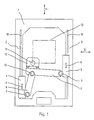
- the machine tool shown only partially in the drawing is used for 3-axis Machining workpieces. It has a machine frame from which only one frame 1 is shown, the one lying in an X-Y plane Frame cheeks 2, 3 opposite and parallel to each other, Have guides 18, 19 for slides 4, 5 slidable thereon.
- everyone Carriage 4 and 5 has a drive, not shown, with which the Carriage 4 or 5 in the direction of the double arrow 6 along its guide is adjustable.
- the drives can be operated independently of each other.
- Each carriage 4 and 5 carries a joint 7 for a coupling 8 mounted thereon and 9.
- the two couplers 8 and 9 are in the area of their ends facing away from the slide via a further joint 10 connected.
- the axes of the joints 7, 10 are parallel to each other and in substantially orthogonal to that of the frame cheeks 2, 3 or those thereon arranged guides defined X-Y plane aligned.
- the coupling 9 is on the Joint 10 facing away from the coupling 9, a tool holder 11 attached.
- the tool carrier 11 has a slide 12 which is orthogonal to the X-Y plane, So in the Z direction with the help of a drive, not shown is adjustable.
- the carriage carries a tool, not shown.
- the couplers 8, 9 have different lengths, the lengths of the Couplings 8, 9 are set up such that the couplers 8, 9 in all Operating positions form an angle between them, which is in the range of 90 ° lies.
Landscapes
- Engineering & Computer Science (AREA)
- Mechanical Engineering (AREA)
- Machine Tool Units (AREA)
Description
- Figur 1
- schematisch und teilweise das Maschinengestell einer Werkzeugmaschine mit einem darin angeordneten Koppelsystem,
- Figuren 2 bis 4
- andere Funktionsstellungen des Gegenstandes nach Figur 1.
Claims (3)
- Werkzeugmaschine zur 3-achsigen Bearbeitung von Werkstücken mit einem Maschinengestell, mit schwenkbar gelagerten, in einer X-Y-Ebene verstellbaren Koppeln (8, 9), die gelenkig miteinander verbunden sind, mit einem an einer Koppel (9) angeordneten Werkzeugträger (11), der einen in der von der X-Y-Ebene unabhängigen Z-Richtung beweglichen Schlitten (12) aufweist, und mit voneinander unabhängigen Antrieben zum Verstellen der Koppeln (8, 9), dadurch gekennzeichnet, dass zwei Koppeln (8, 9) an zwei Schlitten (4, 5) gelagert sind, welche in gestellfesten Führungen (18, 19) mit Hilfe je eines Antriebes verstellbar sind, wobei die Führungen (18, 19) im wesentlichen zueinander parallel angeordnet sind und die Koppeln (8, 9) im Bereich ihrer den Schlitten (4, 5) abgewandten Enden gelenkig miteinander verbunden sind und, betrachtet in der Projektion auf eine X-Y-Ebene, zwischen den Führungen (18, 19) liegen, und dass der Werkzeugträger (11) im Bereich des freien Endes einer Koppel (9) angeordnet ist .
- Werkzeugmaschine nach Anspruch 1, dadurch gekennzeichnet, dass die Koppeln (8, 9) unterschiedliche Länge besitzen.
- Werkzeugmaschine nach Anspruch 1 oder 2, dadurch gekennzeichnet, dass die Koppeln (8, 9) bei allen Betriebsstellungen zwischen sich einen Winkel im Bereich von 90° bilden.
Applications Claiming Priority (4)
| Application Number | Priority Date | Filing Date | Title |
|---|---|---|---|
| DE19745991 | 1997-10-20 | ||
| DE19745991 | 1997-10-20 | ||
| DE19806085A DE19806085B4 (de) | 1997-10-20 | 1998-02-14 | Werkzeugmaschine zur 3-achsigen Bearbeitung von Werkstücken |
| DE19806085 | 1998-02-14 |
Publications (2)
| Publication Number | Publication Date |
|---|---|
| EP0916446A1 EP0916446A1 (de) | 1999-05-19 |
| EP0916446B1 true EP0916446B1 (de) | 2002-05-02 |
Family
ID=26040922
Family Applications (1)
| Application Number | Title | Priority Date | Filing Date |
|---|---|---|---|
| EP98115050A Expired - Lifetime EP0916446B1 (de) | 1997-10-20 | 1998-08-11 | Werkzeugmaschine zur 3-achsigen Bearbeitung von Werkstücken |
Country Status (4)
| Country | Link |
|---|---|
| US (1) | US6328510B1 (de) |
| EP (1) | EP0916446B1 (de) |
| AT (1) | ATE216939T1 (de) |
| BR (1) | BR9803876A (de) |
Families Citing this family (33)
| Publication number | Priority date | Publication date | Assignee | Title |
|---|---|---|---|---|
| DE69916862T2 (de) * | 1999-02-26 | 2005-04-21 | Mori Seiki Seisakusho Kk | Werkzeugmaschine |
| US6402444B1 (en) * | 1999-04-29 | 2002-06-11 | Tsinghua University | Type of parallel machine tool frame driven by slider and extensible strut |
| DE19963342A1 (de) * | 1999-12-27 | 2001-06-28 | Grob Gmbh & Co Kg | Werkzeugmaschine |
| ES2161184B1 (es) * | 1999-12-28 | 2002-07-01 | Consejo Superior Investigacion | Un dispositivo de un elemento de trabajo con dos grados de movilidad. |
| DE50102146D1 (de) | 2000-06-29 | 2004-06-03 | Hueller Hille Gmbh | Werkzeug-maschine zur mindestens 3-achsigen bearbeitung von werkstücken |
| DE10206414A1 (de) | 2001-03-16 | 2002-10-02 | Siemens Ag | Vorrichtung zur Positionierung eines Werkzeugs innerhalb eines vorgegebenen Arbeitsbereichs |
| CZ299124B6 (cs) | 2001-06-18 | 2008-04-30 | Kovosvit Mas A.S. | Paralelní polohovací mechanismus, zvlášte pro obrábení a/nebo manipulaci a/nebo merení |
| US6761518B2 (en) | 2001-09-11 | 2004-07-13 | HüLLER HILLE GMBH | Machine tool |
| NL1019443C2 (nl) * | 2001-11-27 | 2003-06-02 | R P T Weekers Holding B V | Manipulator voor het verplaatsen van een gereedschap. |
| DE10209141A1 (de) * | 2002-03-01 | 2003-09-18 | Siemens Ag | Verfahren zur Kalibrierung von parallelkinematisch in einem Bewegungsraum bewegten Maschineneinheiten in Werkzeugmaschinen und Handhabungsgeräten |
| US6823595B1 (en) * | 2002-05-03 | 2004-11-30 | Ronald C Bellavich | Table top X-Y carriage for use with quilting frame |
| US6817104B2 (en) * | 2002-05-15 | 2004-11-16 | Sumitomo Heavy Industries, Ltd. | X-Y stage apparatus |
| DE10224577A1 (de) * | 2002-06-03 | 2003-12-11 | Kessler Kg Maschf | Vorrichtung zur Bearbeitung von Werkstücken sowie Maschinenanordnung hierzu |
| EP1493538B1 (de) * | 2003-06-27 | 2009-07-01 | Siemens Aktiengesellschaft | Bestimmungsverfahren für Istzustände einer Anzahl von Verstellelementen |
| CZ303752B6 (cs) * | 2006-01-04 | 2013-04-24 | CVUT v Praze - fakulta strojní | Zpusob a zarízení pro merení a/nebo kalibraci polohy telesa v prostoru |
| TWI302862B (en) * | 2006-05-18 | 2008-11-11 | Univ Chung Yuan Christian | Toggle-type positioning platform and toggle-type machine center |
| DE602007006034D1 (de) * | 2006-09-21 | 2010-06-02 | Airbus Operations Sas | Vorrichtung zur überkopfbearbeitung fixierter elemente |
| US20080087128A1 (en) * | 2006-10-12 | 2008-04-17 | Garner Timothy D | Cross-wedge motion platform |
| US20100307278A1 (en) * | 2007-11-26 | 2010-12-09 | Motor Power Company S.R.L. | device for handling and/or performing work operations on objects |
| WO2010006466A1 (zh) * | 2008-07-16 | 2010-01-21 | 北京航空航天大学 | 非对称直线驱动的平动加转动进给功能部件 |
| TWI367144B (en) * | 2009-05-05 | 2012-07-01 | Univ Chung Yuan Christian | Three-link toggle type positioning platform |
| TWI371334B (en) * | 2009-05-05 | 2012-09-01 | Univ Chung Yuan Christian | Toggle type with one axial positioning machine |
| TWI395633B (zh) * | 2010-04-23 | 2013-05-11 | 私立中原大學 | 肘節式定位平台 |
| DE102010047308A1 (de) * | 2010-10-01 | 2012-04-05 | Weiß GmbH Sondermaschinentechnik | Manipulationsvorrichtung |
| CN102120205B (zh) * | 2011-02-23 | 2012-09-19 | 常州大学 | 一种单喷枪喷涂五轴混联机器人 |
| US9764464B2 (en) * | 2011-08-03 | 2017-09-19 | The Boeing Company | Robot including telescopic assemblies for positioning an end effector |
| CN103878624B (zh) * | 2012-12-20 | 2016-04-13 | 财团法人精密机械研究发展中心 | 双轴并联进给平台机构 |
| US9682454B2 (en) * | 2014-04-21 | 2017-06-20 | Robert James Suhling | Micro-adjustable flip-away work stop for strut systems |
| US9709216B2 (en) * | 2015-03-13 | 2017-07-18 | Spencer Zing | Safety securing apparatus |
| JP6557053B2 (ja) * | 2015-05-13 | 2019-08-07 | 株式会社京都製作所 | 移送装置 |
| CN106378637B (zh) * | 2016-11-18 | 2018-03-30 | 电子科技大学 | 一种用于机床加工的气液并联六自由度加工平台系统 |
| US11383336B2 (en) | 2020-06-18 | 2022-07-12 | Robert James Suhling | Reversible flip-away work stop for strut systems |
| US12415290B2 (en) | 2023-08-23 | 2025-09-16 | Robert J. SUHLING | Cutting tool fence apparatus with measuring ruler and moveable material stop component |
Family Cites Families (16)
| Publication number | Priority date | Publication date | Assignee | Title |
|---|---|---|---|---|
| GB292227A (en) * | 1927-03-14 | 1928-06-14 | Percy Arthur Stedman | Improvements in devices for supporting portable power driven tools, such as drills, riveting apparatus and the like |
| US3618465A (en) * | 1970-02-10 | 1971-11-09 | Michel Brochard | Cutting device |
| US4972574A (en) * | 1988-06-08 | 1990-11-27 | Mamiya Denshi Co., Ltd. | Table driving apparatus |
| US4962676A (en) * | 1989-10-12 | 1990-10-16 | The Gillette Company | Two axis transfer device |
| DE4040307C2 (de) * | 1990-12-17 | 1996-03-07 | Eden Medizinische Elektronik G | Vorrichtung zur Positionierung eines Doppler-Signalgebers und/oder -aufnehmers |
| US5267818A (en) * | 1991-08-05 | 1993-12-07 | Optima Industries, Inc. | Arrangement for providing planar movement of a machine tool |
| US5569004A (en) * | 1993-06-22 | 1996-10-29 | Optima Industries, Inc. | Machine tool positioning arrangement |
| US5378282A (en) * | 1993-06-28 | 1995-01-03 | Pollard; Willard L. | Robotic tool manipulating apparatus |
| DE19525482A1 (de) * | 1995-07-13 | 1997-01-16 | Bernold Richerzhagen | Vorrichtung zur Verschiebung und Positionierung eines Objektes in einer Ebene |
| JP3626265B2 (ja) * | 1995-12-18 | 2005-03-02 | 本田技研工業株式会社 | 工作機械 |
| US6099217A (en) * | 1995-12-20 | 2000-08-08 | Wiegand; Alexander Konrad | Device for spatially moving a body with three to six degrees of freedom in a controlled manner |
| EP0791438B1 (de) * | 1996-02-07 | 2002-05-29 | Verein Deutscher Werkzeugmaschinenfabriken e.V. (VDW) | Vorrichtung zur Bewegung eines Körpers im Raum |
| DE19623511A1 (de) * | 1996-06-13 | 1997-12-18 | Vdw Ev | Vorrichtung zur Bearbeitung und/oder Montage von Werkstücken |
| US5886494A (en) * | 1997-02-06 | 1999-03-23 | Camelot Systems, Inc. | Positioning system |
| US5903125A (en) * | 1997-02-06 | 1999-05-11 | Speedline Technologies, Inc. | Positioning system |
| AT411446B (de) * | 1998-08-03 | 2004-01-26 | Ernst Krause & Co | Arbeitsstation |
-
1998
- 1998-08-11 AT AT98115050T patent/ATE216939T1/de not_active IP Right Cessation
- 1998-08-11 EP EP98115050A patent/EP0916446B1/de not_active Expired - Lifetime
- 1998-09-28 US US09/161,891 patent/US6328510B1/en not_active Expired - Fee Related
- 1998-10-06 BR BR9803876-1A patent/BR9803876A/pt not_active IP Right Cessation
Also Published As
| Publication number | Publication date |
|---|---|
| ATE216939T1 (de) | 2002-05-15 |
| US6328510B1 (en) | 2001-12-11 |
| EP0916446A1 (de) | 1999-05-19 |
| BR9803876A (pt) | 1999-12-07 |
Similar Documents
| Publication | Publication Date | Title |
|---|---|---|
| EP0916446A1 (de) | Werkzeugmaschine zur 3-achsigen Bearbeitung von Werkstücken | |
| EP1998930B1 (de) | Positioniereinrichtung | |
| EP0418826B1 (de) | Einrichtung zur Simulation auf der Erde von Operationen eines im Weltraum einsetzbaren Manipulators an einem Modell eines Raumfahrzeuges | |
| DE602004013188T2 (de) | Kinematischer parallelmanipulator für grossen arbeitsraum | |
| EP0812652B1 (de) | Vorrichtung zur Bearbeitung und/oder Montage von Werkstücken | |
| DE69403345T2 (de) | Wellenkupplung | |
| DE19836624C1 (de) | Werkzeugmaschine mit Koppelführung | |
| CH621286A5 (de) | ||
| DE10391447B4 (de) | Hybrider Parallelmanipulator zum Verfahren eines Arbeitskopfes im Raum | |
| DE19806085B4 (de) | Werkzeugmaschine zur 3-achsigen Bearbeitung von Werkstücken | |
| EP0590123B1 (de) | Spurbreitenveränderliches fahrwerk | |
| DE3404553A1 (de) | Handhabungseinrichtung, insbesondere zum be- und entladen von werkzeugmaschinen | |
| DE69001771T2 (de) | Anordnung zur Handhabung von Bohrstangen in einem Gesteinsbohraggregat oder dgl. | |
| DE10211055B4 (de) | Bewegungs- und/oder Positioniervorrichtung | |
| EP1228838B1 (de) | Kinematische Vorrichtung zum Bewegen eines Trägers | |
| DE2354420B2 (de) | Klappenbetaetigungsanordnung an einem tragfluegel fuer luftfahrzeuge | |
| EP0624309B1 (de) | Landwirtschaftliche Arbeitsmaschine | |
| EP1738880B1 (de) | Manipulator mit Schwenkantrieben und Lineartrieben zur Handhabung von Werkzeugen oder Werkstücken | |
| DE102010024623B4 (de) | Präzisionswerkzeugmaschine | |
| DE102005001845A1 (de) | Stabilisator für eine Portalwerkzeugmaschine und Portalwerkzeugmaschine | |
| EP0468138A1 (de) | Vorderradaufhängung für Motorräder | |
| DE102023125303A1 (de) | F2-Roboter mit zusätzlichem Kopplungsmittel in der Parallelogramm-Führung der Roboter-Hand | |
| DE3739953A1 (de) | Positioniereinrichtung fuer die herstellung von halbleiterbauelementen | |
| DE10012348B4 (de) | Bewegungs- und/oder Positioniervorrichtung | |
| DE19651934A1 (de) | Transferpresse |
Legal Events
| Date | Code | Title | Description |
|---|---|---|---|
| PUAI | Public reference made under article 153(3) epc to a published international application that has entered the european phase |
Free format text: ORIGINAL CODE: 0009012 |
|
| 17P | Request for examination filed |
Effective date: 19980811 |
|
| AK | Designated contracting states |
Kind code of ref document: A1 Designated state(s): AT BE CH DE ES FR GB IT LI NL PT SE |
|
| AX | Request for extension of the european patent |
Free format text: AL;LT;LV;MK;RO;SI |
|
| AKX | Designation fees paid |
Free format text: AT BE CH DE ES FR GB IT LI NL PT SE |
|
| GRAG | Despatch of communication of intention to grant |
Free format text: ORIGINAL CODE: EPIDOS AGRA |
|
| RIN1 | Information on inventor provided before grant (corrected) |
Inventor name: STENGELE, GERALD Inventor name: HANRATH, GEORG, DR. |
|
| 17Q | First examination report despatched |
Effective date: 20011015 |
|
| GRAG | Despatch of communication of intention to grant |
Free format text: ORIGINAL CODE: EPIDOS AGRA |
|
| REG | Reference to a national code |
Ref country code: GB Ref legal event code: IF02 |
|
| GRAG | Despatch of communication of intention to grant |
Free format text: ORIGINAL CODE: EPIDOS AGRA |
|
| GRAH | Despatch of communication of intention to grant a patent |
Free format text: ORIGINAL CODE: EPIDOS IGRA |
|
| GRAH | Despatch of communication of intention to grant a patent |
Free format text: ORIGINAL CODE: EPIDOS IGRA |
|
| GRAA | (expected) grant |
Free format text: ORIGINAL CODE: 0009210 |
|
| AK | Designated contracting states |
Kind code of ref document: B1 Designated state(s): AT BE CH DE ES FR GB IT LI NL PT SE |
|
| PG25 | Lapsed in a contracting state [announced via postgrant information from national office to epo] |
Ref country code: NL Free format text: LAPSE BECAUSE OF FAILURE TO SUBMIT A TRANSLATION OF THE DESCRIPTION OR TO PAY THE FEE WITHIN THE PRESCRIBED TIME-LIMIT Effective date: 20020502 Ref country code: GB Free format text: LAPSE BECAUSE OF FAILURE TO SUBMIT A TRANSLATION OF THE DESCRIPTION OR TO PAY THE FEE WITHIN THE PRESCRIBED TIME-LIMIT Effective date: 20020502 |
|
| REF | Corresponds to: |
Ref document number: 216939 Country of ref document: AT Date of ref document: 20020515 Kind code of ref document: T |
|
| REG | Reference to a national code |
Ref country code: GB Ref legal event code: FG4D Free format text: NOT ENGLISH |
|
| REG | Reference to a national code |
Ref country code: CH Ref legal event code: EP |
|
| REF | Corresponds to: |
Ref document number: 59803973 Country of ref document: DE Date of ref document: 20020606 |
|
| ET | Fr: translation filed | ||
| PG25 | Lapsed in a contracting state [announced via postgrant information from national office to epo] |
Ref country code: SE Free format text: LAPSE BECAUSE OF FAILURE TO SUBMIT A TRANSLATION OF THE DESCRIPTION OR TO PAY THE FEE WITHIN THE PRESCRIBED TIME-LIMIT Effective date: 20020802 Ref country code: PT Free format text: LAPSE BECAUSE OF FAILURE TO SUBMIT A TRANSLATION OF THE DESCRIPTION OR TO PAY THE FEE WITHIN THE PRESCRIBED TIME-LIMIT Effective date: 20020802 |
|
| PG25 | Lapsed in a contracting state [announced via postgrant information from national office to epo] |
Ref country code: AT Free format text: LAPSE BECAUSE OF NON-PAYMENT OF DUE FEES Effective date: 20020811 |
|
| PG25 | Lapsed in a contracting state [announced via postgrant information from national office to epo] |
Ref country code: LI Free format text: LAPSE BECAUSE OF NON-PAYMENT OF DUE FEES Effective date: 20020831 Ref country code: CH Free format text: LAPSE BECAUSE OF NON-PAYMENT OF DUE FEES Effective date: 20020831 Ref country code: BE Free format text: LAPSE BECAUSE OF NON-PAYMENT OF DUE FEES Effective date: 20020831 |
|
| NLV1 | Nl: lapsed or annulled due to failure to fulfill the requirements of art. 29p and 29m of the patents act | ||
| GBV | Gb: ep patent (uk) treated as always having been void in accordance with gb section 77(7)/1977 [no translation filed] |
Effective date: 20020502 |
|
| PG25 | Lapsed in a contracting state [announced via postgrant information from national office to epo] |
Ref country code: ES Free format text: LAPSE BECAUSE OF FAILURE TO SUBMIT A TRANSLATION OF THE DESCRIPTION OR TO PAY THE FEE WITHIN THE PRESCRIBED TIME-LIMIT Effective date: 20021128 |
|
| BERE | Be: lapsed |
Owner name: *HULLER HILLE G.M.B.H. Effective date: 20020831 |
|
| PLBE | No opposition filed within time limit |
Free format text: ORIGINAL CODE: 0009261 |
|
| STAA | Information on the status of an ep patent application or granted ep patent |
Free format text: STATUS: NO OPPOSITION FILED WITHIN TIME LIMIT |
|
| REG | Reference to a national code |
Ref country code: CH Ref legal event code: PL |
|
| 26N | No opposition filed |
Effective date: 20030204 |
|
| PGFP | Annual fee paid to national office [announced via postgrant information from national office to epo] |
Ref country code: IT Payment date: 20100826 Year of fee payment: 13 Ref country code: FR Payment date: 20100901 Year of fee payment: 13 |
|
| REG | Reference to a national code |
Ref country code: DE Ref legal event code: R081 Ref document number: 59803973 Country of ref document: DE Owner name: MAG IAS GMBH, DE Free format text: FORMER OWNER: CROSS HUELLER GMBH, 71636 LUDWIGSBURG, DE Effective date: 20110223 |
|
| REG | Reference to a national code |
Ref country code: FR Ref legal event code: ST Effective date: 20120430 |
|
| PG25 | Lapsed in a contracting state [announced via postgrant information from national office to epo] |
Ref country code: IT Free format text: LAPSE BECAUSE OF NON-PAYMENT OF DUE FEES Effective date: 20110811 |
|
| PG25 | Lapsed in a contracting state [announced via postgrant information from national office to epo] |
Ref country code: FR Free format text: LAPSE BECAUSE OF NON-PAYMENT OF DUE FEES Effective date: 20110831 |
|
| PGFP | Annual fee paid to national office [announced via postgrant information from national office to epo] |
Ref country code: DE Payment date: 20121024 Year of fee payment: 15 |
|
| PG25 | Lapsed in a contracting state [announced via postgrant information from national office to epo] |
Ref country code: DE Free format text: LAPSE BECAUSE OF NON-PAYMENT OF DUE FEES Effective date: 20140301 |
|
| REG | Reference to a national code |
Ref country code: DE Ref legal event code: R119 Ref document number: 59803973 Country of ref document: DE Effective date: 20140301 |