EP0916027B1 - Seitenkanalverdichter - Google Patents
Seitenkanalverdichter Download PDFInfo
- Publication number
- EP0916027B1 EP0916027B1 EP97935424A EP97935424A EP0916027B1 EP 0916027 B1 EP0916027 B1 EP 0916027B1 EP 97935424 A EP97935424 A EP 97935424A EP 97935424 A EP97935424 A EP 97935424A EP 0916027 B1 EP0916027 B1 EP 0916027B1
- Authority
- EP
- European Patent Office
- Prior art keywords
- ring
- housing
- sealing ring
- sealing
- compressor
- Prior art date
- Legal status (The legal status is an assumption and is not a legal conclusion. Google has not performed a legal analysis and makes no representation as to the accuracy of the status listed.)
- Expired - Lifetime
Links
- 238000007789 sealing Methods 0.000 claims abstract description 27
- 230000000284 resting effect Effects 0.000 abstract 1
- 230000000694 effects Effects 0.000 description 1
- 238000009434 installation Methods 0.000 description 1
- 238000000034 method Methods 0.000 description 1
Images
Classifications
-
- F—MECHANICAL ENGINEERING; LIGHTING; HEATING; WEAPONS; BLASTING
- F04—POSITIVE - DISPLACEMENT MACHINES FOR LIQUIDS; PUMPS FOR LIQUIDS OR ELASTIC FLUIDS
- F04D—NON-POSITIVE-DISPLACEMENT PUMPS
- F04D29/00—Details, component parts, or accessories
- F04D29/08—Sealings
- F04D29/083—Sealings especially adapted for elastic fluid pumps
-
- F—MECHANICAL ENGINEERING; LIGHTING; HEATING; WEAPONS; BLASTING
- F04—POSITIVE - DISPLACEMENT MACHINES FOR LIQUIDS; PUMPS FOR LIQUIDS OR ELASTIC FLUIDS
- F04D—NON-POSITIVE-DISPLACEMENT PUMPS
- F04D23/00—Other rotary non-positive-displacement pumps
- F04D23/008—Regenerative pumps
Definitions
- the invention relates to a side channel compressor, according to the Preamble of claim 1.
- Such a side channel compressor is known from EP-A-0 708 248 known.
- this known compressor there is a sealing ring by means of a retaining ring against one on the housing of the Side channel compressor clamped contact surface held.
- the sealing ring extends in the radial direction to the one that carries the blades of the side channel blower Support ring and lies on its inner circumference. To one To achieve good sealing, the sealing ring must be on everyone Place the inner circumference properly. This sets in very precise centric alignment of the sealing ring ahead, what only through a correspondingly high installation effort to achieve.
- the invention has for its object a side channel compressor of the generic type so that the Sealing ring in a simple manner with high alignment accuracy can be assembled.
- the task is solved by the in the license plate of claim 1 specified features.
- the sealing ring only needs in the centering edge for precise alignment to be indented.
- the centering edge itself can be in can be easily produced by a turning process
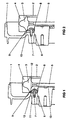
- Impeller 2 With 1 is a housing half of a side channel compressor housing designated. Two to one full case joined housing halves 1 enclose one a drive shaft, not shown in the drawing Impeller 2.
- the impeller 2 has on its outer circumference a support ring 3 on which the conveyor blades 4 of the Impeller 2 are arranged.
- the support ring 3 is on one the drive shaft plugged in and rotatably connected to it Hub part 5 arranged.
- a sealing arrangement intended On each housing half 1 is in the radially inside the Support ring 3 at this adjacent area, a sealing arrangement intended. This consists of a plastic sealing ring 6, which is fastened by means of screws 7 Retaining ring 8 against a corresponding one on the housing wall the respective housing half 1 provided contact surface is held.
- the central alignment of the sealing ring 6 takes place by means of one provided on the respective housing half 1 Centering edge 10.
- the sealing ring 6 then only needs to be pushed in behind this centering edge 10.
- By the centering edge 10 results in a positive fixation of the sealing ring 6, thereby causing the sealing ring to move away 6 is prevented radially outwards.
- the sealing ring 6 corresponds to the outside diameter of the sealing ring 6 the inner diameter of the Centering edge 10.
- the sealing ring 6 is in the axial direction dimensioned accordingly thick so that it is opposite the centering edge 10 projects axially and engages in the corner recess, being on the axially extending wall portion of the Corner recess 9 abuts and thus between the impeller 2 and seals the respective housing half 1 existing gap 13.
Landscapes
- Engineering & Computer Science (AREA)
- Mechanical Engineering (AREA)
- General Engineering & Computer Science (AREA)
- Structures Of Non-Positive Displacement Pumps (AREA)
- Massaging Devices (AREA)
- Shaping Of Tube Ends By Bending Or Straightening (AREA)
- Percussion Or Vibration Massage (AREA)
Abstract
Description
- FIG 1
- einen Teillängsschnitt eines Seitenkanalverdichters mit einer ersten Ausführungsform eines Zentrier-randes.
- FIG 2
- einen Teillängsschnitt eines Seitenkanalverdichters mit einer zweiten Ausführungsform eines Zentrier-randes.
Claims (1)
- Seitenkanalverdichter, mit einem in seinem Gehäuse (1) drehbar angeordneten Laufrad (2), das einen mit Förderschaufeln (4) besetzten Tragring (3) aufweist, der ein ihn tragendes und mit einer Antriebswelle verbindendes Nabenteil (5) zumindest auf einer Seite axial überragt, bei welchem Verdichter im Bereich des Tragringes (3) ein am Innenumfang des axial überstehenden Teiles des Tragringes (3) anliegender, sich radial erstreckender, den zwischen dem Laufrad (2) und dem Gehäuse (1) bestehenden Spalt (13) abdichtender Dichtungsring (6) mittels eines Halteringes (8) gegen eine am Gehäuse (1,2) vorgesehene Anlagefläche eingespannt gehalten ist,
dadurch gekennzeichnet, daß an der Anlagefläche ein den Dichtungsring (6) ausrichtender Zentrierrand (10) vorgesehen ist.
Applications Claiming Priority (3)
| Application Number | Priority Date | Filing Date | Title |
|---|---|---|---|
| DE29613186U | 1996-07-30 | ||
| DE29613186U DE29613186U1 (de) | 1996-07-30 | 1996-07-30 | Seitenkanalverdichter |
| PCT/DE1997/001492 WO1998004836A1 (de) | 1996-07-30 | 1997-07-15 | Seitenkanalverdichter |
Publications (2)
| Publication Number | Publication Date |
|---|---|
| EP0916027A1 EP0916027A1 (de) | 1999-05-19 |
| EP0916027B1 true EP0916027B1 (de) | 2002-01-09 |
Family
ID=8027180
Family Applications (1)
| Application Number | Title | Priority Date | Filing Date |
|---|---|---|---|
| EP97935424A Expired - Lifetime EP0916027B1 (de) | 1996-07-30 | 1997-07-15 | Seitenkanalverdichter |
Country Status (5)
| Country | Link |
|---|---|
| US (1) | US6129508A (de) |
| EP (1) | EP0916027B1 (de) |
| JP (1) | JP3082477U (de) |
| DE (2) | DE29613186U1 (de) |
| WO (1) | WO1998004836A1 (de) |
Families Citing this family (5)
| Publication number | Priority date | Publication date | Assignee | Title |
|---|---|---|---|---|
| RU2384745C1 (ru) * | 2009-02-18 | 2010-03-20 | Открытое акционерное общество Научно-производственное объединение "Искра" | Двухсекционный центробежный компрессор |
| RU2428589C1 (ru) * | 2010-04-29 | 2011-09-10 | Открытое акционерное общество Научно-производственное объединение "Искра" | Центробежный компрессор |
| RU2442026C1 (ru) * | 2010-07-30 | 2012-02-10 | Закрытое акционерное общество "Научно-исследовательский и конструкторский институт центробежных и роторных компрессоров им. В.Б. Шнеппа" | Способ саморегулирующей разгрузки упорного подшипника центробежного компрессора |
| RU2442027C1 (ru) * | 2010-08-06 | 2012-02-10 | Закрытое акционерное общество "Научно-исследовательский и конструкторский институт центробежных и роторных компрессоров им.В.Б. Шнеппа" | Узел разгрузки упорного подшипника двухсекционного центробежного компрессора с расположением рабочих колес "спина к спине" |
| EP2816966B1 (de) | 2012-02-22 | 2023-10-25 | Veran Medical Technologies, Inc. | Lenkbarer chirurgischer katheter mit einer biopsievorrichtung an seinem distalen endteil |
Family Cites Families (6)
| Publication number | Priority date | Publication date | Assignee | Title |
|---|---|---|---|---|
| CH560326A5 (de) * | 1972-09-13 | 1975-03-27 | Siemens Ag | |
| US4279570A (en) * | 1978-03-31 | 1981-07-21 | The Garrett Corporation | Energy transfer machine |
| JPS59128993A (ja) * | 1983-01-10 | 1984-07-25 | Hitachi Ltd | 渦流れ形ポンプ |
| US5143511A (en) * | 1990-09-28 | 1992-09-01 | Lamson Corporation | Regenerative centrifugal compressor |
| DE4244458A1 (en) * | 1991-12-27 | 1993-07-01 | Mitsubishi Electric Corp | Electric pump supplying by=pass air to vehicle catalytic converters - circulates air inside motor case for cooling of motor, and has noise absorbers in air suction port |
| US5658126A (en) * | 1994-10-20 | 1997-08-19 | Siemens Aktiengesellschaft | Side channel compressor |
-
1996
- 1996-07-30 DE DE29613186U patent/DE29613186U1/de not_active Expired - Lifetime
-
1997
- 1997-07-15 WO PCT/DE1997/001492 patent/WO1998004836A1/de not_active Ceased
- 1997-07-15 JP JP1999600002U patent/JP3082477U/ja not_active Expired - Lifetime
- 1997-07-15 DE DE59706125T patent/DE59706125D1/de not_active Expired - Fee Related
- 1997-07-15 US US09/230,475 patent/US6129508A/en not_active Expired - Fee Related
- 1997-07-15 EP EP97935424A patent/EP0916027B1/de not_active Expired - Lifetime
Also Published As
| Publication number | Publication date |
|---|---|
| US6129508A (en) | 2000-10-10 |
| DE59706125D1 (de) | 2002-02-28 |
| WO1998004836A1 (de) | 1998-02-05 |
| DE29613186U1 (de) | 1996-09-19 |
| EP0916027A1 (de) | 1999-05-19 |
| JP3082477U (ja) | 2001-12-14 |
Similar Documents
| Publication | Publication Date | Title |
|---|---|---|
| DE3712567C2 (de) | ||
| DE69005510T2 (de) | Pumpe um Gas von einer zu pumpenden Flüssigkeit abzutrennen. | |
| DE19747127A1 (de) | Abdichtvorrichtung | |
| DE2537538B2 (de) | Befestigung eines Verdichterlaufrades an einer Welle | |
| DE69311948T2 (de) | Lageranordnung zur Verwendung in einem Spaltrohrmotor | |
| DE3300064C2 (de) | Wellendichteinheit | |
| DE3035984A1 (de) | Optischer wandler zum ermitteln der winkelstellung eines sich drehenden elements mit bezug auf eine feste konstruktion | |
| DE2526505A1 (de) | Stroemungsmesser | |
| DE2210305C3 (de) | Filter in einem Brennstoffspeisesystem für Brennkraftmaschinen | |
| EP0847498A1 (de) | Seitenkanalkreiselpumpe | |
| DE2158518C3 (de) | Horizontale mehrstufige Zentrifugalpumpe | |
| EP0916027A1 (de) | Seitenkanalverdichter | |
| DE3526517C2 (de) | ||
| EP0708248B1 (de) | Seitenkanalverdichter | |
| EP0706001A1 (de) | Radialwellendichtung | |
| DE2403854C3 (de) | Rotor für einen induktiven Meßfühler | |
| EP0742371B1 (de) | Flüssigkeitsringmaschine | |
| WO1994004854A1 (de) | Druckdeckel für kreiselpumpen | |
| EP0218015B1 (de) | Verfahren zur Herstellung einer innenachsigen Drehkolbenmaschine | |
| DE2922951C2 (de) | Flügelzellenpumpe | |
| DE19611677A1 (de) | Berührungsfreie Dichtung mit einem schwimmenden Ring | |
| EP0584106B1 (de) | Mehrflutige flüssigkeitsringpumpe | |
| EP0576449B1 (de) | Seitenkanalverdichter | |
| DE2125042A1 (de) | Strömungsmaschine mit einem Laufrad mit mehreren Kanälen | |
| CH664299A5 (de) | Vorrichtung zum polieren bzw. schaelen von reis. |
Legal Events
| Date | Code | Title | Description |
|---|---|---|---|
| PUAI | Public reference made under article 153(3) epc to a published international application that has entered the european phase |
Free format text: ORIGINAL CODE: 0009012 |
|
| 17P | Request for examination filed |
Effective date: 19990120 |
|
| AK | Designated contracting states |
Kind code of ref document: A1 Designated state(s): DE GB IT |
|
| GRAG | Despatch of communication of intention to grant |
Free format text: ORIGINAL CODE: EPIDOS AGRA |
|
| GRAG | Despatch of communication of intention to grant |
Free format text: ORIGINAL CODE: EPIDOS AGRA |
|
| GRAH | Despatch of communication of intention to grant a patent |
Free format text: ORIGINAL CODE: EPIDOS IGRA |
|
| 17Q | First examination report despatched |
Effective date: 20010605 |
|
| GRAH | Despatch of communication of intention to grant a patent |
Free format text: ORIGINAL CODE: EPIDOS IGRA |
|
| GRAA | (expected) grant |
Free format text: ORIGINAL CODE: 0009210 |
|
| REG | Reference to a national code |
Ref country code: GB Ref legal event code: IF02 |
|
| AK | Designated contracting states |
Kind code of ref document: B1 Designated state(s): DE GB IT |
|
| REF | Corresponds to: |
Ref document number: 59706125 Country of ref document: DE Date of ref document: 20020228 |
|
| GBT | Gb: translation of ep patent filed (gb section 77(6)(a)/1977) |
Effective date: 20020406 |
|
| PGFP | Annual fee paid to national office [announced via postgrant information from national office to epo] |
Ref country code: GB Payment date: 20020621 Year of fee payment: 6 |
|
| PLBE | No opposition filed within time limit |
Free format text: ORIGINAL CODE: 0009261 |
|
| STAA | Information on the status of an ep patent application or granted ep patent |
Free format text: STATUS: NO OPPOSITION FILED WITHIN TIME LIMIT |
|
| 26N | No opposition filed | ||
| PG25 | Lapsed in a contracting state [announced via postgrant information from national office to epo] |
Ref country code: GB Free format text: LAPSE BECAUSE OF NON-PAYMENT OF DUE FEES Effective date: 20030715 |
|
| GBPC | Gb: european patent ceased through non-payment of renewal fee |
Effective date: 20030715 |
|
| PGFP | Annual fee paid to national office [announced via postgrant information from national office to epo] |
Ref country code: IT Payment date: 20070830 Year of fee payment: 11 Ref country code: DE Payment date: 20071001 Year of fee payment: 11 |
|
| PG25 | Lapsed in a contracting state [announced via postgrant information from national office to epo] |
Ref country code: DE Free format text: LAPSE BECAUSE OF NON-PAYMENT OF DUE FEES Effective date: 20090203 |
|
| PG25 | Lapsed in a contracting state [announced via postgrant information from national office to epo] |
Ref country code: IT Free format text: LAPSE BECAUSE OF NON-PAYMENT OF DUE FEES Effective date: 20080715 |