EP0915307A1 - Kondensor für Klimaanlage mit Flüssigkeitsbehälter mit auswechselbarer Patrone - Google Patents
Kondensor für Klimaanlage mit Flüssigkeitsbehälter mit auswechselbarer Patrone Download PDFInfo
- Publication number
- EP0915307A1 EP0915307A1 EP98120654A EP98120654A EP0915307A1 EP 0915307 A1 EP0915307 A1 EP 0915307A1 EP 98120654 A EP98120654 A EP 98120654A EP 98120654 A EP98120654 A EP 98120654A EP 0915307 A1 EP0915307 A1 EP 0915307A1
- Authority
- EP
- European Patent Office
- Prior art keywords
- tank
- base
- condenser according
- cartridge
- fluid
- Prior art date
- Legal status (The legal status is an assumption and is not a legal conclusion. Google has not performed a legal analysis and makes no representation as to the accuracy of the status listed.)
- Granted
Links
Images


Classifications
-
- F—MECHANICAL ENGINEERING; LIGHTING; HEATING; WEAPONS; BLASTING
- F25—REFRIGERATION OR COOLING; COMBINED HEATING AND REFRIGERATION SYSTEMS; HEAT PUMP SYSTEMS; MANUFACTURE OR STORAGE OF ICE; LIQUEFACTION SOLIDIFICATION OF GASES
- F25B—REFRIGERATION MACHINES, PLANTS OR SYSTEMS; COMBINED HEATING AND REFRIGERATION SYSTEMS; HEAT PUMP SYSTEMS
- F25B39/00—Evaporators; Condensers
- F25B39/04—Condensers
-
- B—PERFORMING OPERATIONS; TRANSPORTING
- B60—VEHICLES IN GENERAL
- B60H—ARRANGEMENTS OF HEATING, COOLING, VENTILATING OR OTHER AIR-TREATING DEVICES SPECIALLY ADAPTED FOR PASSENGER OR GOODS SPACES OF VEHICLES
- B60H1/00—Heating, cooling or ventilating [HVAC] devices
- B60H1/32—Cooling devices
- B60H1/3204—Cooling devices using compression
- B60H1/3227—Cooling devices using compression characterised by the arrangement or the type of heat exchanger, e.g. condenser, evaporator
-
- F—MECHANICAL ENGINEERING; LIGHTING; HEATING; WEAPONS; BLASTING
- F25—REFRIGERATION OR COOLING; COMBINED HEATING AND REFRIGERATION SYSTEMS; HEAT PUMP SYSTEMS; MANUFACTURE OR STORAGE OF ICE; LIQUEFACTION SOLIDIFICATION OF GASES
- F25B—REFRIGERATION MACHINES, PLANTS OR SYSTEMS; COMBINED HEATING AND REFRIGERATION SYSTEMS; HEAT PUMP SYSTEMS
- F25B43/00—Arrangements for separating or purifying gases or liquids; Arrangements for vaporising the residuum of liquid refrigerant, e.g. by heat
- F25B43/003—Filters
-
- F—MECHANICAL ENGINEERING; LIGHTING; HEATING; WEAPONS; BLASTING
- F25—REFRIGERATION OR COOLING; COMBINED HEATING AND REFRIGERATION SYSTEMS; HEAT PUMP SYSTEMS; MANUFACTURE OR STORAGE OF ICE; LIQUEFACTION SOLIDIFICATION OF GASES
- F25B—REFRIGERATION MACHINES, PLANTS OR SYSTEMS; COMBINED HEATING AND REFRIGERATION SYSTEMS; HEAT PUMP SYSTEMS
- F25B2339/00—Details of evaporators; Details of condensers
- F25B2339/04—Details of condensers
- F25B2339/044—Condensers with an integrated receiver
- F25B2339/0441—Condensers with an integrated receiver containing a drier or a filter
-
- F—MECHANICAL ENGINEERING; LIGHTING; HEATING; WEAPONS; BLASTING
- F25—REFRIGERATION OR COOLING; COMBINED HEATING AND REFRIGERATION SYSTEMS; HEAT PUMP SYSTEMS; MANUFACTURE OR STORAGE OF ICE; LIQUEFACTION SOLIDIFICATION OF GASES
- F25B—REFRIGERATION MACHINES, PLANTS OR SYSTEMS; COMBINED HEATING AND REFRIGERATION SYSTEMS; HEAT PUMP SYSTEMS
- F25B2339/00—Details of evaporators; Details of condensers
- F25B2339/04—Details of condensers
- F25B2339/044—Condensers with an integrated receiver
- F25B2339/0446—Condensers with an integrated receiver characterised by the refrigerant tubes connecting the header of the condenser to the receiver; Inlet or outlet connections to receiver
-
- F—MECHANICAL ENGINEERING; LIGHTING; HEATING; WEAPONS; BLASTING
- F25—REFRIGERATION OR COOLING; COMBINED HEATING AND REFRIGERATION SYSTEMS; HEAT PUMP SYSTEMS; MANUFACTURE OR STORAGE OF ICE; LIQUEFACTION SOLIDIFICATION OF GASES
- F25B—REFRIGERATION MACHINES, PLANTS OR SYSTEMS; COMBINED HEATING AND REFRIGERATION SYSTEMS; HEAT PUMP SYSTEMS
- F25B2500/00—Problems to be solved
- F25B2500/01—Geometry problems, e.g. for reducing size
-
- F—MECHANICAL ENGINEERING; LIGHTING; HEATING; WEAPONS; BLASTING
- F25—REFRIGERATION OR COOLING; COMBINED HEATING AND REFRIGERATION SYSTEMS; HEAT PUMP SYSTEMS; MANUFACTURE OR STORAGE OF ICE; LIQUEFACTION SOLIDIFICATION OF GASES
- F25B—REFRIGERATION MACHINES, PLANTS OR SYSTEMS; COMBINED HEATING AND REFRIGERATION SYSTEMS; HEAT PUMP SYSTEMS
- F25B40/00—Subcoolers, desuperheaters or superheaters
- F25B40/02—Subcoolers
Definitions
- the invention relates to a condenser, in particular for a fluid.
- refrigerant in a cabin air conditioning system of a motor vehicle comprising a manifold and an elongated intermediate tank for treatment and / or the accumulation of a fluid, which binds so removable on a base secured to the manifold, crossed by two connecting pipes for the transfer of fluid between the manifold and the tank.
- the tank intermediary can fulfill all or part of the functions following: filtration and / or dehydration of the refrigerant, compensation for variations in the volume thereof, separation of liquid and gas phases. His position intermediate with respect to the condenser circulate in the part of it located downstream of the tank only fluid in the liquid state, which is thus sub-cooled below the liquid / gas equilibrium temperature, improving the performance of the condenser and making these relatively independent of the amount of fluid contained in the circuit.
- EP-A-0 480 330 describes, in an air conditioning condenser of vehicle, an intermediate tank which is fixed so removable on a base secured to the manifold, crossed by the two connecting pipes.
- This tank is provided at its lower end with a head integral with its wall, which is fixed to the base by means of a screw.
- the connecting pipes partly extend in the base and partly in the tank head.
- the object of the invention is to remedy the above drawbacks.
- the invention relates in particular to a condenser comprising a box collector and an elongated intermediate tank for the treatment and accumulation of a fluid, which attaches to removably on a base secured to the. box collector, crossed by two connecting pipes for the transfer of fluid between the manifold and the tank.
- the tank is provided in the vicinity of a first of its ends of means for fixing to the base, and contains an interchangeable treatment cartridge which can be removed from the first end when the tank is separated from the base, said pipes link extending therein with regard to said first end.
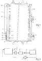
- FIG. 3 is a diagram of a refrigerant circuit being part of a cabin air conditioning system of a motor vehicle.
- this circuit successively includes a compressor 1, a set 2 hereinafter referred to as the condenser, a regulator 3 and an evaporator 4.
- the condenser 2 has an upstream section 2a in which the refrigerant transfers heat to an air flow so as to condense, after being the if necessary "desuperheated" from a temperature input higher than the liquid / gas equilibrium temperature.
- Section 2a is followed by an intermediate tank 2b, then a downstream section 2c in which the fluid is sub-cooled by heat exchange with the air flow.
- An embodiment of the condenser 2 is shown in its general structure in Figures 1 and 2. It includes two manifolds 2d, 2e vertically elongated and spaced from each other in a horizontal direction, interconnected by a multiplicity of circulation tubes horizontal fluid 5. Each manifold is divided into different rooms by horizontal partitions 6 so that the fluid circulates in the tubes 5, alternatively from a room in the 2d box to a room the 2nd box and vice versa, from the upper chamber of the 2nd box, which communicates with an inlet pipe 7, up to the lower chamber of the same 2nd box, which communicates with an outlet pipe 8.
- One of the intermediate partitions of the manifold 2d separates one from the other of the rooms 9-1 and 9-2, located above and below respectively of partition 6-1, and which communicate with each other exclusively through the reservoir 2b, which is vertically elongated and extends along the box 2d.
- the reservoir 2b comprises a housing formed by a body cylindrical 11 occupying most of its height, and a narrowed neck 12 disposed at its lower part.
- Pass 12 presents in turn a region 13 provided with a male thread and, below this threaded region, one more region 14 small diameter, hollowed out by two circumferential grooves for housing two O-rings 15.
- a filter and dehydrating cartridge 20 is disposed in the reservoir 2b, along the longitudinal axis thereof.
- This cartridge has a tubular casing 21 which can be closed at its upper end 22 and which is crossed by orifices 23 distributed over its height.
- the envelope is lined with particles suitable for filtering and dehydrating the fluid.
- the envelope 21 is divided in its height in three regions of different cross sections.
- Region 24 is followed down by a region 25 whose cross section is reduced by the arrangement of two diametrically opposite flats 26.
- a lower region 27 again presents a circular cross section, slightly diameter less than the distance between the flats 26.
- the part region 25 and region 27 protrude below of the neck 12 of the reservoir by forming a tubing of exit
- the tank 2b is in mechanical and communication link of fluid with the manifold 2d via a base 30 which is shown in detail in the figures 4 and 5.
- This base is preferably a part molded in aluminum alloy, defining a wall 31 of substantially revolution around a vertical axis 32, which is also the axis tank and cartridge.
- the wall 31 delimits a bore 33 open upwards to receive the neck of the tank 2b.
- the lateral surface of the bore 33 has in an upper region a female thread 34 cooperating with the thread 13 of the tank.
- a cylindrical middle region 35 cooperates with the seals 15, and a cylindrical lower region 36 surrounds the tubing 25, 27 and defines with the region 27 an annular space 37 which communicates with the interior of the tank by two chimneys 38 located opposite the flats 26.
- a web 39 extending substantially along a plane passing through the axis 32.
- This veil presents, on either side of this plane, bulges 40 which allow to house two pipes 41, 42 elongated parallel to this plan.
- the pipe 41 opens with its two ends respectively in the bore 33, at the annular space 37, and in the edge free from veil 39, and is inclined upwards from one towards the other.
- Line 42 extends horizontally from the free edge of the veil to the bottom of bore 33, at which it connects.
- brazed plugs 43, 44 shown in Figure 2 seal the free ends of the pipes 41, 42 and the latter open to the outside of the base exclusively by passages 45, 46 formed in lateral bosses 47, 48 trained on bulges 40.
- the tubular wall 21 of the cartridge has a rib outer circumference 50, formed of two parts diametrically opposed, each extending in an arc between the two flats 26 of the region 25.
- the rib 50 is trapped, when screwing the tank on the base, between the lower end 51 of the neck and a shoulder 52 of the wall 31 located opposite it.
- Rib 50 has inclined upper and lower faces which cooperate with chamfers on the neck and on the wall 31.
- the cartridge positioning is completed by adjustment from the lower end 53 of the lower region 27 in bore 34, immediately below a shoulder 54 of this which limits the annular space downwards 37.
- the region 27 has an inclined annular lip 55 the free edge of which rests on the shoulder 54.
- a seal flat annular seal 56 is clamped between the end free 57 of the wall 31 and the radial shoulder 58 connecting the neck 12 to the body 11 of the reservoir.
- the base 30 is fixed to the manifold 2d by soldering of the ends of the bosses 47, 48 on the outer face of the tubular aluminum sheet wall of the box, when assembly of the condenser by brazing.
- Passages 45 and 46 communicate with rooms 9-1 and 9-2 respectively of the fluid box through holes provided in the tubular wall of it.
- the condensed fluid reaching the chamber 9-1 passes from it to annular space 37 through the passage 45 and the inclined pipe 41, then enters the tank 2b, screwed into the base, via the chimneys 38.
- the liquid phase then passes, through the holes 23, into the cartridge where it flows from top to bottom while being dried out and filtered by the active particles contained therein, while the possible residual gas phase collects at the top of the tank.
- the fluid leaves the tank, exclusively in liquid state, through the tubing 25, 27, and reaches chamber 9-2 of the manifold 2d by the horizontal pipe 42 and the passage 46.
- the tubes 5 and the chambers of the boxes 2d and 2e located above that partition 6-1, including room 9-1 constitutes the upstream section 2a of the condenser, while the tubes and the rooms located lower than this partition, including the chamber 9-2, constitute the downstream section 2c.
- a retaining flange 60 mechanically connects the end higher of the tank 2b than that of the manifold 2d for a more stable fixing of the tank.
- Replacing the cartridge is particularly simple, since it is enough to unscrew the tank, to extract the used cartridge, insert a new cartridge and screw the tank back on.
Landscapes
- Engineering & Computer Science (AREA)
- Physics & Mathematics (AREA)
- Mechanical Engineering (AREA)
- Thermal Sciences (AREA)
- General Engineering & Computer Science (AREA)
- Chemical & Material Sciences (AREA)
- Analytical Chemistry (AREA)
- Power Engineering (AREA)
- Air-Conditioning For Vehicles (AREA)
Applications Claiming Priority (2)
| Application Number | Priority Date | Filing Date | Title |
|---|---|---|---|
| FR9714099 | 1997-11-10 | ||
| FR9714099A FR2770896B1 (fr) | 1997-11-10 | 1997-11-10 | Condenseur de climatisation muni d'un reservoir de fluide a cartouche interchangeable |
Publications (2)
| Publication Number | Publication Date |
|---|---|
| EP0915307A1 true EP0915307A1 (de) | 1999-05-12 |
| EP0915307B1 EP0915307B1 (de) | 2003-08-20 |
Family
ID=9513213
Family Applications (1)
| Application Number | Title | Priority Date | Filing Date |
|---|---|---|---|
| EP98120654A Expired - Lifetime EP0915307B1 (de) | 1997-11-10 | 1998-11-04 | Kondensor für Klimaanlage mit Flüssigkeitsbehälter mit auswechselbarer Patrone |
Country Status (6)
| Country | Link |
|---|---|
| US (1) | US6158503A (de) |
| EP (1) | EP0915307B1 (de) |
| JP (1) | JPH11264634A (de) |
| BR (1) | BR9804569A (de) |
| DE (1) | DE69817296T2 (de) |
| FR (1) | FR2770896B1 (de) |
Cited By (7)
| Publication number | Priority date | Publication date | Assignee | Title |
|---|---|---|---|---|
| EP1048909A2 (de) * | 1999-04-26 | 2000-11-02 | Ti Group Automotive Systems Limited | Filtertrockner für Kältekreislauf |
| EP1089043A1 (de) * | 1999-09-28 | 2001-04-04 | Valeo Thermique Moteur | Kondensator mit dicht und lösbar am Anschlussstutzen montiertem Sammler |
| FR2801664A1 (fr) * | 1999-11-30 | 2001-06-01 | Valeo Thermique Moteur Sa | Condenseur comprenant un reservoir integre fixe de maniere amovible sur une embase |
| EP1744112A2 (de) | 2005-07-13 | 2007-01-17 | Jahn GmbH | Trockner für ein Kühlmedium in einem Kühlmediumkreislauf, insbesondere für eine Klimaanlage eines Fahrzeugs |
| EP1746367A3 (de) * | 2005-07-20 | 2008-01-23 | Fujikoki Corporation | Sammler-Trockner und Verflüssiger mit integriertem Sammler-Trockner |
| EP2110623A1 (de) * | 2008-04-17 | 2009-10-21 | SHOWA ALUMINIUM CZECH, s.r.o. | Wärmetauscher |
| CN101943539A (zh) * | 2010-09-29 | 2011-01-12 | 浙江金宸三普换热器有限公司 | 热交换器的集流管结构 |
Families Citing this family (31)
| Publication number | Priority date | Publication date | Assignee | Title |
|---|---|---|---|---|
| JP4041634B2 (ja) * | 1999-03-30 | 2008-01-30 | カルソニックカンセイ株式会社 | 凝縮器 |
| KR20020001968A (ko) * | 2000-06-29 | 2002-01-09 | 배길훈 | 자동차용 리시버드라이어 일체형 컨덴서 |
| US6450252B1 (en) * | 2001-08-15 | 2002-09-17 | Lih Yann Co., Ltd. | Oil changing unit having heat exchanger |
| EP1319908B1 (de) * | 2001-12-12 | 2006-12-27 | Sanden Corporation | Wärmetauscher |
| DE10164668A1 (de) * | 2001-12-28 | 2003-07-10 | Behr Lorraine S A R L Europole | Gelöteter Kondensator |
| DE10203481A1 (de) * | 2002-01-30 | 2003-08-14 | Hansa Metallwerke Ag | Kältemitteltrockner für Klima- oder Kälteanlagen, insbesondere für Fahrzeug-Klimaanlagen |
| TWI280340B (en) * | 2002-02-20 | 2007-05-01 | Showa Denko Kk | Heat exchanger with receiver tank, receiver tank connecting member, receiver tank mounting structure of heat exchanger and refrigeration system |
| DE502004009238D1 (de) * | 2003-11-14 | 2009-05-07 | Behr Gmbh & Co Kg | Wärmetauscher |
| JP4624363B2 (ja) * | 2003-12-11 | 2011-02-02 | ベール・ゲーエムベーハー・ウント・コ・カーゲー | 熱交換装置用の構造機構 |
| EP1548380A3 (de) * | 2003-12-22 | 2006-10-04 | Hussmann Corporation | Flachrohrverdampfer mit Mikroverteiler |
| KR100908769B1 (ko) * | 2005-02-02 | 2009-07-22 | 캐리어 코포레이션 | 병류 열교환기와, 균일한 냉매 유동을 촉진하는 방법 |
| DE102005005187A1 (de) * | 2005-02-03 | 2006-08-10 | Behr Gmbh & Co. Kg | Kondensator für eine Klimaanlage, insbesondere eines Kraftfahrzeuges |
| JP4836510B2 (ja) * | 2005-07-20 | 2011-12-14 | 株式会社不二工機 | レシーバドライヤ |
| EP1764569B1 (de) * | 2005-09-16 | 2013-11-27 | Behr GmbH & Co. KG | Sammler mit Trockner-/Filtereinheit für einen Kondensator |
| US20070095505A1 (en) * | 2005-10-28 | 2007-05-03 | Thomas Robinson | Starter controller coolant outlet flow kit |
| US8607852B2 (en) | 2007-11-14 | 2013-12-17 | Swep International Ab | Distribution pipe |
| EP2369269A4 (de) * | 2008-12-15 | 2014-02-26 | Calsonic Kansei Corp | Wärmetauscher und herstellungsverfahren dafür |
| CN101691981B (zh) * | 2009-07-23 | 2011-12-07 | 三花丹佛斯(杭州)微通道换热器有限公司 | 具有改进的制冷剂流体分配均匀性的多通道换热器 |
| JP5593084B2 (ja) * | 2009-07-29 | 2014-09-17 | 株式会社ケーヒン・サーマル・テクノロジー | 熱交換器 |
| JP5624299B2 (ja) * | 2009-10-05 | 2014-11-12 | 株式会社不二工機 | レシーバドライヤ |
| US20110290465A1 (en) * | 2010-06-01 | 2011-12-01 | Delphi Technologies, Inc. | Orientation insensitive refrigerant distributor tube |
| FR2965336B1 (fr) | 2010-09-28 | 2012-09-14 | Valeo Systemes Thermiques | Ensemble d'un echangeur de chaleur biphasique et d'une bouteille |
| WO2014117002A1 (en) * | 2013-01-25 | 2014-07-31 | Trane International Inc. | Refrigerant outlet device of a condenser |
| US20150041414A1 (en) * | 2013-08-09 | 2015-02-12 | Ledwell & Son Enterprises, Inc. | Hydraulic fluid cooler and filter |
| EP2960613B1 (de) * | 2014-06-25 | 2020-10-21 | VALEO AUTOSYSTEMY Sp. Z. o.o. | Sammler für einen Wärmetauscher und damit ausgestatteter Wärmetauscher, insbesondere Kondensator |
| US10072900B2 (en) * | 2014-09-16 | 2018-09-11 | Mahle International Gmbh | Heat exchanger distributor with intersecting streams |
| CN107208946B (zh) * | 2014-12-22 | 2020-05-01 | C·邱 | 用于改善热交换系统效率的装置 |
| DE102016112574B3 (de) * | 2016-07-08 | 2018-01-04 | Konvekta Aktiengesellschaft | Kältemittelsammler für Klimaanlage |
| EP3503314A4 (de) * | 2016-08-16 | 2020-04-08 | Furukawa Electric Co., Ltd. | Drehbare konnektorvorrichtung |
| EP3803233B1 (de) | 2018-06-02 | 2024-03-06 | Carrier Corporation | Wassergekühlter wärmetauscher |
| JP7114831B2 (ja) * | 2019-03-29 | 2022-08-09 | 日軽熱交株式会社 | 熱交換器用レシーバタンク |
Citations (4)
| Publication number | Priority date | Publication date | Assignee | Title |
|---|---|---|---|---|
| DE3416304A1 (de) * | 1984-05-03 | 1985-11-07 | Knecht Filterwerke Gmbh, 7000 Stuttgart | Demontagehilfe fuer filtergehaeuse insbesondere fuer schmieroelfilter bei verbrennungsmotoren |
| CH683556A5 (de) * | 1991-06-10 | 1994-03-31 | Walter Albert Bruno Haeusler | Adapter für Heizöl-Filtereinrichtungen. |
| JPH0953868A (ja) * | 1995-08-10 | 1997-02-25 | Calsonic Corp | 凝縮器 |
| EP0769666A1 (de) * | 1995-10-18 | 1997-04-23 | Calsonic Corporation | Verflüssiger mit Flüssigkeitsbehälter |
Family Cites Families (9)
| Publication number | Priority date | Publication date | Assignee | Title |
|---|---|---|---|---|
| FR2622685B1 (fr) * | 1987-10-29 | 1990-01-19 | Vicarb Sa | Echangeur de chaleur gaz/liquide avec condensation |
| JP3081941B2 (ja) * | 1990-08-23 | 2000-08-28 | 株式会社ゼクセル | レシーバタンク一体型コンデンサ |
| DE4421834A1 (de) * | 1994-06-22 | 1996-01-04 | Behr Gmbh & Co | Einsatz für einen Kondensator einer Klimaanlage eines Fahrzeuges |
| US5901573A (en) * | 1995-11-02 | 1999-05-11 | Calsonic Corporation | Condenser structure with liquid tank |
| US5868002A (en) * | 1996-07-29 | 1999-02-09 | Showa Aluminum Corporation | Condenser with a liquid-receiver |
| JPH10122705A (ja) * | 1996-10-14 | 1998-05-15 | Calsonic Corp | リキッドタンク付コンデンサ |
| FR2754887B1 (fr) * | 1996-10-23 | 1998-12-31 | Valeo Thermique Moteur Sa | Condenseur a reservoir amovible pour circuit de refrigeration, en particulier de vehicule automobile |
| DE19712714A1 (de) * | 1997-03-26 | 1998-10-01 | Behr Gmbh & Co | Einsatz für ein Sammlerprofil eines Kondensators |
| US6000465A (en) * | 1997-06-27 | 1999-12-14 | Mitsubishi Heavy Industries, Ltd. | Heat exchange with a receiver |
-
1997
- 1997-11-10 FR FR9714099A patent/FR2770896B1/fr not_active Expired - Lifetime
-
1998
- 1998-11-04 EP EP98120654A patent/EP0915307B1/de not_active Expired - Lifetime
- 1998-11-04 DE DE69817296T patent/DE69817296T2/de not_active Expired - Lifetime
- 1998-11-05 BR BR9804569-5A patent/BR9804569A/pt not_active IP Right Cessation
- 1998-11-09 US US09/188,576 patent/US6158503A/en not_active Expired - Lifetime
- 1998-11-10 JP JP10318754A patent/JPH11264634A/ja active Pending
Patent Citations (4)
| Publication number | Priority date | Publication date | Assignee | Title |
|---|---|---|---|---|
| DE3416304A1 (de) * | 1984-05-03 | 1985-11-07 | Knecht Filterwerke Gmbh, 7000 Stuttgart | Demontagehilfe fuer filtergehaeuse insbesondere fuer schmieroelfilter bei verbrennungsmotoren |
| CH683556A5 (de) * | 1991-06-10 | 1994-03-31 | Walter Albert Bruno Haeusler | Adapter für Heizöl-Filtereinrichtungen. |
| JPH0953868A (ja) * | 1995-08-10 | 1997-02-25 | Calsonic Corp | 凝縮器 |
| EP0769666A1 (de) * | 1995-10-18 | 1997-04-23 | Calsonic Corporation | Verflüssiger mit Flüssigkeitsbehälter |
Non-Patent Citations (1)
| Title |
|---|
| PATENT ABSTRACTS OF JAPAN vol. 097, no. 006 30 June 1997 (1997-06-30) * |
Cited By (14)
| Publication number | Priority date | Publication date | Assignee | Title |
|---|---|---|---|---|
| EP1048909A2 (de) * | 1999-04-26 | 2000-11-02 | Ti Group Automotive Systems Limited | Filtertrockner für Kältekreislauf |
| EP1048909A3 (de) * | 1999-04-26 | 2001-02-07 | Ti Group Automotive Systems Limited | Filtertrockner für Kältekreislauf |
| EP1089043A1 (de) * | 1999-09-28 | 2001-04-04 | Valeo Thermique Moteur | Kondensator mit dicht und lösbar am Anschlussstutzen montiertem Sammler |
| FR2799821A1 (fr) * | 1999-09-28 | 2001-04-20 | Valeo Thermique Moteur Sa | Condenseur comprenant un reservoir fixe de maniere amovible et etanche sur une embase |
| US6301926B1 (en) | 1999-09-28 | 2001-10-16 | Valeo Thermique Moteur | Condenser, including a reservoir, mounted on a base in such a way as to be removable and watertight |
| FR2801664A1 (fr) * | 1999-11-30 | 2001-06-01 | Valeo Thermique Moteur Sa | Condenseur comprenant un reservoir integre fixe de maniere amovible sur une embase |
| EP1744112A2 (de) | 2005-07-13 | 2007-01-17 | Jahn GmbH | Trockner für ein Kühlmedium in einem Kühlmediumkreislauf, insbesondere für eine Klimaanlage eines Fahrzeugs |
| DE102005033168A1 (de) * | 2005-07-13 | 2007-01-25 | Jahn Gmbh Umform- Und Zerspanungstechnik | Trockner für ein Kühlmedium in einem Kühlmediumkreislauf, insbesondere für eine Klimaanlage eines Fahrzeugs |
| DE102005033168B4 (de) * | 2005-07-13 | 2009-04-16 | Jahn Gmbh Umform- Und Zerspanungstechnik | Trockner für ein Kühlmedium in einem Kühlmediumkreislauf, insbesondere für eine Klimaanlage eines Fahrzeugs |
| EP1746367A3 (de) * | 2005-07-20 | 2008-01-23 | Fujikoki Corporation | Sammler-Trockner und Verflüssiger mit integriertem Sammler-Trockner |
| US7712330B2 (en) | 2005-07-20 | 2010-05-11 | Fujikoki Corporation | Receiver dryer and receiver dryer integrated condenser |
| EP2110623A1 (de) * | 2008-04-17 | 2009-10-21 | SHOWA ALUMINIUM CZECH, s.r.o. | Wärmetauscher |
| CN101943539A (zh) * | 2010-09-29 | 2011-01-12 | 浙江金宸三普换热器有限公司 | 热交换器的集流管结构 |
| CN101943539B (zh) * | 2010-09-29 | 2011-12-07 | 浙江金宸三普换热器有限公司 | 热交换器的集流管结构 |
Also Published As
| Publication number | Publication date |
|---|---|
| FR2770896A1 (fr) | 1999-05-14 |
| DE69817296T2 (de) | 2004-05-27 |
| DE69817296D1 (de) | 2003-09-25 |
| BR9804569A (pt) | 1999-10-26 |
| JPH11264634A (ja) | 1999-09-28 |
| EP0915307B1 (de) | 2003-08-20 |
| FR2770896B1 (fr) | 2000-01-28 |
| US6158503A (en) | 2000-12-12 |
Similar Documents
| Publication | Publication Date | Title |
|---|---|---|
| EP0915307B1 (de) | Kondensor für Klimaanlage mit Flüssigkeitsbehälter mit auswechselbarer Patrone | |
| EP0915308A1 (de) | Kondensator für Klimaanlage mit wechselbarem Flüssigkeitsbehälter | |
| EP0838642B1 (de) | Verflüssiger mit lösbarem Sammler für Kühlkreislauf, insbesondere von einem Kraftfahrzeug | |
| FR2947041A1 (fr) | Condenseur avec reserve de fluide frigorigene pour circuit de climatisation | |
| EP1640676B1 (de) | Vorrichtung, die einen inneren Wärmetauscher und Akkumulator für einen Kreislauf einer Klimaanlage kombiniert | |
| FR2766914A1 (fr) | Distributeur destine a equiper les echangeurs thermiques intratubulaires des installations de refroidissement a fluide frigorigene de type diphasique | |
| FR2924490A1 (fr) | Condenseur pour circuit de climatisation avec partie de sous-refroidissement | |
| EP0774102A1 (de) | Verflüssiger mit einbezogenem behälter für klimaanlage eines kraftfahrzeuges | |
| FR2709344A1 (fr) | Condenseur pour installation de climatisation de véhicule automobile. | |
| FR2923899A1 (fr) | Condenseur pour circuit de climatisation avec bouteille integree | |
| WO2010060657A1 (fr) | Condenseur pour circuit de climatisation avec echangeur interne integre | |
| FR2962199A1 (fr) | Condenseur, notamment pour systeme de climatisation d'un vehicule automobile. | |
| EP0990106B1 (de) | Kondensator für klimaanlage mit sammler montiert an halterung | |
| EP1089043A1 (de) | Kondensator mit dicht und lösbar am Anschlussstutzen montiertem Sammler | |
| FR2940418A1 (fr) | Dispositif combine comprenant un echangeur de chaleur interne et un accumulateur | |
| EP1817536A1 (de) | Wärmetauscher mit mindestens einem flansch für den verteiler des wärmetauschers und behälter dafür | |
| EP0454559B1 (de) | Endkammer mit Ausdehnungsgefäss für einen Wärmetauscher, zum Beispiel einen Kühler und Wärmetauscher mit einer derartigen Vorrichtung | |
| FR2747768A1 (fr) | Condenseur pour circuit de refrigeration, en particulier pour la climatisation d'un vehicule automobile | |
| FR2674289A1 (fr) | Dispositif de refroidissement en mode diphasique pour moteur a combustion interne. | |
| FR2741428A1 (fr) | Reservoir de fluide frigorigene pour installation de pompe a chaleur | |
| WO2002063226A1 (fr) | Condenseur comprenant un reservoir integre fixe sur une embase | |
| FR2872261A1 (fr) | Reservoir ameliore pour un echangeur de chaleur, par exemple un condenseur de climatisation | |
| FR2801664A1 (fr) | Condenseur comprenant un reservoir integre fixe de maniere amovible sur une embase | |
| FR2826437A1 (fr) | Dispositif de raccordement pour evaporateur de climatisation de vehicule | |
| FR2776759A1 (fr) | Condenseur a boites collectrices couplees par un reservoir, notamment pour un circuit de climatisation de vehicule automobile |
Legal Events
| Date | Code | Title | Description |
|---|---|---|---|
| PUAI | Public reference made under article 153(3) epc to a published international application that has entered the european phase |
Free format text: ORIGINAL CODE: 0009012 |
|
| AK | Designated contracting states |
Kind code of ref document: A1 Designated state(s): DE |
|
| AX | Request for extension of the european patent |
Free format text: AL;LT;LV;MK;RO;SI |
|
| 17P | Request for examination filed |
Effective date: 19991110 |
|
| AKX | Designation fees paid |
Free format text: DE |
|
| GRAH | Despatch of communication of intention to grant a patent |
Free format text: ORIGINAL CODE: EPIDOS IGRA |
|
| GRAH | Despatch of communication of intention to grant a patent |
Free format text: ORIGINAL CODE: EPIDOS IGRA |
|
| GRAA | (expected) grant |
Free format text: ORIGINAL CODE: 0009210 |
|
| AK | Designated contracting states |
Designated state(s): DE |
|
| RAP1 | Party data changed (applicant data changed or rights of an application transferred) |
Owner name: VALEO THERMIQUE MOTEUR |
|
| REF | Corresponds to: |
Ref document number: 69817296 Country of ref document: DE Date of ref document: 20030925 Kind code of ref document: P |
|
| PLBE | No opposition filed within time limit |
Free format text: ORIGINAL CODE: 0009261 |
|
| STAA | Information on the status of an ep patent application or granted ep patent |
Free format text: STATUS: NO OPPOSITION FILED WITHIN TIME LIMIT |
|
| 26N | No opposition filed |
Effective date: 20040524 |
|
| PGFP | Annual fee paid to national office [announced via postgrant information from national office to epo] |
Ref country code: DE Payment date: 20161115 Year of fee payment: 19 |
|
| REG | Reference to a national code |
Ref country code: DE Ref legal event code: R119 Ref document number: 69817296 Country of ref document: DE |
|
| PG25 | Lapsed in a contracting state [announced via postgrant information from national office to epo] |
Ref country code: DE Free format text: LAPSE BECAUSE OF NON-PAYMENT OF DUE FEES Effective date: 20180602 |