EP0914935B1 - Vorrichtung zum Verschweissen von Kunststoffbahnen - Google Patents
Vorrichtung zum Verschweissen von Kunststoffbahnen Download PDFInfo
- Publication number
- EP0914935B1 EP0914935B1 EP98123347A EP98123347A EP0914935B1 EP 0914935 B1 EP0914935 B1 EP 0914935B1 EP 98123347 A EP98123347 A EP 98123347A EP 98123347 A EP98123347 A EP 98123347A EP 0914935 B1 EP0914935 B1 EP 0914935B1
- Authority
- EP
- European Patent Office
- Prior art keywords
- hot air
- welding
- opening
- nozzle
- films
- Prior art date
- Legal status (The legal status is an assumption and is not a legal conclusion. Google has not performed a legal analysis and makes no representation as to the accuracy of the status listed.)
- Expired - Lifetime
Links
Images


Classifications
-
- B—PERFORMING OPERATIONS; TRANSPORTING
- B29—WORKING OF PLASTICS; WORKING OF SUBSTANCES IN A PLASTIC STATE IN GENERAL
- B29C—SHAPING OR JOINING OF PLASTICS; SHAPING OF MATERIAL IN A PLASTIC STATE, NOT OTHERWISE PROVIDED FOR; AFTER-TREATMENT OF THE SHAPED PRODUCTS, e.g. REPAIRING
- B29C65/00—Joining or sealing of preformed parts, e.g. welding of plastics materials; Apparatus therefor
- B29C65/02—Joining or sealing of preformed parts, e.g. welding of plastics materials; Apparatus therefor by heating, with or without pressure
- B29C65/10—Joining or sealing of preformed parts, e.g. welding of plastics materials; Apparatus therefor by heating, with or without pressure using hot gases (e.g. combustion gases) or flames coming in contact with at least one of the parts to be joined
- B29C65/103—Joining or sealing of preformed parts, e.g. welding of plastics materials; Apparatus therefor by heating, with or without pressure using hot gases (e.g. combustion gases) or flames coming in contact with at least one of the parts to be joined direct heating both surfaces to be joined
-
- B—PERFORMING OPERATIONS; TRANSPORTING
- B29—WORKING OF PLASTICS; WORKING OF SUBSTANCES IN A PLASTIC STATE IN GENERAL
- B29C—SHAPING OR JOINING OF PLASTICS; SHAPING OF MATERIAL IN A PLASTIC STATE, NOT OTHERWISE PROVIDED FOR; AFTER-TREATMENT OF THE SHAPED PRODUCTS, e.g. REPAIRING
- B29C66/00—General aspects of processes or apparatus for joining preformed parts
- B29C66/01—General aspects dealing with the joint area or with the area to be joined
- B29C66/02—Preparation of the material, in the area to be joined, prior to joining or welding
- B29C66/022—Mechanical pre-treatments, e.g. reshaping
- B29C66/0224—Mechanical pre-treatments, e.g. reshaping with removal of material
- B29C66/02245—Abrading, e.g. grinding, sanding, sandblasting or scraping
-
- B—PERFORMING OPERATIONS; TRANSPORTING
- B29—WORKING OF PLASTICS; WORKING OF SUBSTANCES IN A PLASTIC STATE IN GENERAL
- B29C—SHAPING OR JOINING OF PLASTICS; SHAPING OF MATERIAL IN A PLASTIC STATE, NOT OTHERWISE PROVIDED FOR; AFTER-TREATMENT OF THE SHAPED PRODUCTS, e.g. REPAIRING
- B29C66/00—General aspects of processes or apparatus for joining preformed parts
- B29C66/01—General aspects dealing with the joint area or with the area to be joined
- B29C66/05—Particular design of joint configurations
- B29C66/10—Particular design of joint configurations particular design of the joint cross-sections
- B29C66/11—Joint cross-sections comprising a single joint-segment, i.e. one of the parts to be joined comprising a single joint-segment in the joint cross-section
- B29C66/112—Single lapped joints
- B29C66/1122—Single lap to lap joints, i.e. overlap joints
-
- B—PERFORMING OPERATIONS; TRANSPORTING
- B29—WORKING OF PLASTICS; WORKING OF SUBSTANCES IN A PLASTIC STATE IN GENERAL
- B29C—SHAPING OR JOINING OF PLASTICS; SHAPING OF MATERIAL IN A PLASTIC STATE, NOT OTHERWISE PROVIDED FOR; AFTER-TREATMENT OF THE SHAPED PRODUCTS, e.g. REPAIRING
- B29C66/00—General aspects of processes or apparatus for joining preformed parts
- B29C66/01—General aspects dealing with the joint area or with the area to be joined
- B29C66/05—Particular design of joint configurations
- B29C66/303—Particular design of joint configurations the joint involving an anchoring effect
- B29C66/3032—Particular design of joint configurations the joint involving an anchoring effect making use of protusions or cavities belonging to at least one of the parts to be joined
- B29C66/30321—Particular design of joint configurations the joint involving an anchoring effect making use of protusions or cavities belonging to at least one of the parts to be joined making use of protusions belonging to at least one of the parts to be joined
- B29C66/30322—Particular design of joint configurations the joint involving an anchoring effect making use of protusions or cavities belonging to at least one of the parts to be joined making use of protusions belonging to at least one of the parts to be joined in the form of rugosity
-
- B—PERFORMING OPERATIONS; TRANSPORTING
- B29—WORKING OF PLASTICS; WORKING OF SUBSTANCES IN A PLASTIC STATE IN GENERAL
- B29C—SHAPING OR JOINING OF PLASTICS; SHAPING OF MATERIAL IN A PLASTIC STATE, NOT OTHERWISE PROVIDED FOR; AFTER-TREATMENT OF THE SHAPED PRODUCTS, e.g. REPAIRING
- B29C66/00—General aspects of processes or apparatus for joining preformed parts
- B29C66/40—General aspects of joining substantially flat articles, e.g. plates, sheets or web-like materials; Making flat seams in tubular or hollow articles; Joining single elements to substantially flat surfaces
- B29C66/41—Joining substantially flat articles ; Making flat seams in tubular or hollow articles
- B29C66/43—Joining a relatively small portion of the surface of said articles
-
- B—PERFORMING OPERATIONS; TRANSPORTING
- B29—WORKING OF PLASTICS; WORKING OF SUBSTANCES IN A PLASTIC STATE IN GENERAL
- B29C—SHAPING OR JOINING OF PLASTICS; SHAPING OF MATERIAL IN A PLASTIC STATE, NOT OTHERWISE PROVIDED FOR; AFTER-TREATMENT OF THE SHAPED PRODUCTS, e.g. REPAIRING
- B29C66/00—General aspects of processes or apparatus for joining preformed parts
- B29C66/70—General aspects of processes or apparatus for joining preformed parts characterised by the composition, physical properties or the structure of the material of the parts to be joined; Joining with non-plastics material
- B29C66/72—General aspects of processes or apparatus for joining preformed parts characterised by the composition, physical properties or the structure of the material of the parts to be joined; Joining with non-plastics material characterised by the structure of the material of the parts to be joined
- B29C66/723—General aspects of processes or apparatus for joining preformed parts characterised by the composition, physical properties or the structure of the material of the parts to be joined; Joining with non-plastics material characterised by the structure of the material of the parts to be joined being multi-layered
-
- B—PERFORMING OPERATIONS; TRANSPORTING
- B29—WORKING OF PLASTICS; WORKING OF SUBSTANCES IN A PLASTIC STATE IN GENERAL
- B29C—SHAPING OR JOINING OF PLASTICS; SHAPING OF MATERIAL IN A PLASTIC STATE, NOT OTHERWISE PROVIDED FOR; AFTER-TREATMENT OF THE SHAPED PRODUCTS, e.g. REPAIRING
- B29C66/00—General aspects of processes or apparatus for joining preformed parts
- B29C66/70—General aspects of processes or apparatus for joining preformed parts characterised by the composition, physical properties or the structure of the material of the parts to be joined; Joining with non-plastics material
- B29C66/73—General aspects of processes or apparatus for joining preformed parts characterised by the composition, physical properties or the structure of the material of the parts to be joined; Joining with non-plastics material characterised by the intensive physical properties of the material of the parts to be joined, by the optical properties of the material of the parts to be joined, by the extensive physical properties of the parts to be joined, by the state of the material of the parts to be joined or by the material of the parts to be joined being a thermoplastic or a thermoset
- B29C66/731—General aspects of processes or apparatus for joining preformed parts characterised by the composition, physical properties or the structure of the material of the parts to be joined; Joining with non-plastics material characterised by the intensive physical properties of the material of the parts to be joined, by the optical properties of the material of the parts to be joined, by the extensive physical properties of the parts to be joined, by the state of the material of the parts to be joined or by the material of the parts to be joined being a thermoplastic or a thermoset characterised by the intensive physical properties of the material of the parts to be joined
- B29C66/7316—Surface properties
- B29C66/73161—Roughness or rugosity
-
- B—PERFORMING OPERATIONS; TRANSPORTING
- B29—WORKING OF PLASTICS; WORKING OF SUBSTANCES IN A PLASTIC STATE IN GENERAL
- B29C—SHAPING OR JOINING OF PLASTICS; SHAPING OF MATERIAL IN A PLASTIC STATE, NOT OTHERWISE PROVIDED FOR; AFTER-TREATMENT OF THE SHAPED PRODUCTS, e.g. REPAIRING
- B29C66/00—General aspects of processes or apparatus for joining preformed parts
- B29C66/80—General aspects of machine operations or constructions and parts thereof
- B29C66/81—General aspects of the pressing elements, i.e. the elements applying pressure on the parts to be joined in the area to be joined, e.g. the welding jaws or clamps
- B29C66/816—General aspects of the pressing elements, i.e. the elements applying pressure on the parts to be joined in the area to be joined, e.g. the welding jaws or clamps characterised by the mounting of the pressing elements, e.g. of the welding jaws or clamps
- B29C66/8167—Quick change joining tools or surfaces
-
- B—PERFORMING OPERATIONS; TRANSPORTING
- B29—WORKING OF PLASTICS; WORKING OF SUBSTANCES IN A PLASTIC STATE IN GENERAL
- B29C—SHAPING OR JOINING OF PLASTICS; SHAPING OF MATERIAL IN A PLASTIC STATE, NOT OTHERWISE PROVIDED FOR; AFTER-TREATMENT OF THE SHAPED PRODUCTS, e.g. REPAIRING
- B29C66/00—General aspects of processes or apparatus for joining preformed parts
- B29C66/80—General aspects of machine operations or constructions and parts thereof
- B29C66/83—General aspects of machine operations or constructions and parts thereof characterised by the movement of the joining or pressing tools
- B29C66/836—Moving relative to and tangentially to the parts to be joined, e.g. transversely to the displacement of the parts to be joined, e.g. using a X-Y table
- B29C66/8362—Rollers, cylinders or drums moving relative to and tangentially to the parts to be joined
-
- B—PERFORMING OPERATIONS; TRANSPORTING
- B29—WORKING OF PLASTICS; WORKING OF SUBSTANCES IN A PLASTIC STATE IN GENERAL
- B29C—SHAPING OR JOINING OF PLASTICS; SHAPING OF MATERIAL IN A PLASTIC STATE, NOT OTHERWISE PROVIDED FOR; AFTER-TREATMENT OF THE SHAPED PRODUCTS, e.g. REPAIRING
- B29C66/00—General aspects of processes or apparatus for joining preformed parts
- B29C66/80—General aspects of machine operations or constructions and parts thereof
- B29C66/84—Specific machine types or machines suitable for specific applications
- B29C66/865—Independently movable welding apparatus, e.g. on wheels
- B29C66/8652—Independently movable welding apparatus, e.g. on wheels being pushed by hand or being self-propelling
- B29C66/86521—Independently movable welding apparatus, e.g. on wheels being pushed by hand or being self-propelling being self-propelling
-
- B—PERFORMING OPERATIONS; TRANSPORTING
- B29—WORKING OF PLASTICS; WORKING OF SUBSTANCES IN A PLASTIC STATE IN GENERAL
- B29C—SHAPING OR JOINING OF PLASTICS; SHAPING OF MATERIAL IN A PLASTIC STATE, NOT OTHERWISE PROVIDED FOR; AFTER-TREATMENT OF THE SHAPED PRODUCTS, e.g. REPAIRING
- B29C66/00—General aspects of processes or apparatus for joining preformed parts
- B29C66/90—Measuring or controlling the joining process
- B29C66/91—Measuring or controlling the joining process by measuring or controlling the temperature, the heat or the thermal flux
- B29C66/914—Measuring or controlling the joining process by measuring or controlling the temperature, the heat or the thermal flux by controlling or regulating the temperature, the heat or the thermal flux
- B29C66/9141—Measuring or controlling the joining process by measuring or controlling the temperature, the heat or the thermal flux by controlling or regulating the temperature, the heat or the thermal flux by controlling or regulating the temperature
-
- B—PERFORMING OPERATIONS; TRANSPORTING
- B29—WORKING OF PLASTICS; WORKING OF SUBSTANCES IN A PLASTIC STATE IN GENERAL
- B29C—SHAPING OR JOINING OF PLASTICS; SHAPING OF MATERIAL IN A PLASTIC STATE, NOT OTHERWISE PROVIDED FOR; AFTER-TREATMENT OF THE SHAPED PRODUCTS, e.g. REPAIRING
- B29C66/00—General aspects of processes or apparatus for joining preformed parts
- B29C66/90—Measuring or controlling the joining process
- B29C66/91—Measuring or controlling the joining process by measuring or controlling the temperature, the heat or the thermal flux
- B29C66/919—Measuring or controlling the joining process by measuring or controlling the temperature, the heat or the thermal flux characterised by specific temperature, heat or thermal flux values or ranges
- B29C66/9192—Measuring or controlling the joining process by measuring or controlling the temperature, the heat or the thermal flux characterised by specific temperature, heat or thermal flux values or ranges in explicit relation to another variable, e.g. temperature diagrams
-
- B—PERFORMING OPERATIONS; TRANSPORTING
- B29—WORKING OF PLASTICS; WORKING OF SUBSTANCES IN A PLASTIC STATE IN GENERAL
- B29C—SHAPING OR JOINING OF PLASTICS; SHAPING OF MATERIAL IN A PLASTIC STATE, NOT OTHERWISE PROVIDED FOR; AFTER-TREATMENT OF THE SHAPED PRODUCTS, e.g. REPAIRING
- B29C66/00—General aspects of processes or apparatus for joining preformed parts
- B29C66/90—Measuring or controlling the joining process
- B29C66/93—Measuring or controlling the joining process by measuring or controlling the speed
- B29C66/934—Measuring or controlling the joining process by measuring or controlling the speed by controlling or regulating the speed
-
- B—PERFORMING OPERATIONS; TRANSPORTING
- B29—WORKING OF PLASTICS; WORKING OF SUBSTANCES IN A PLASTIC STATE IN GENERAL
- B29C—SHAPING OR JOINING OF PLASTICS; SHAPING OF MATERIAL IN A PLASTIC STATE, NOT OTHERWISE PROVIDED FOR; AFTER-TREATMENT OF THE SHAPED PRODUCTS, e.g. REPAIRING
- B29C66/00—General aspects of processes or apparatus for joining preformed parts
- B29C66/90—Measuring or controlling the joining process
- B29C66/93—Measuring or controlling the joining process by measuring or controlling the speed
- B29C66/939—Measuring or controlling the joining process by measuring or controlling the speed characterised by specific speed values or ranges
- B29C66/9392—Measuring or controlling the joining process by measuring or controlling the speed characterised by specific speed values or ranges in explicit relation to another variable, e.g. speed diagrams
-
- E—FIXED CONSTRUCTIONS
- E04—BUILDING
- E04D—ROOF COVERINGS; SKY-LIGHTS; GUTTERS; ROOF-WORKING TOOLS
- E04D15/00—Apparatus or tools for roof working
- E04D15/04—Apparatus or tools for roof working for roof coverings comprising slabs, sheets or flexible material
-
- B—PERFORMING OPERATIONS; TRANSPORTING
- B29—WORKING OF PLASTICS; WORKING OF SUBSTANCES IN A PLASTIC STATE IN GENERAL
- B29C—SHAPING OR JOINING OF PLASTICS; SHAPING OF MATERIAL IN A PLASTIC STATE, NOT OTHERWISE PROVIDED FOR; AFTER-TREATMENT OF THE SHAPED PRODUCTS, e.g. REPAIRING
- B29C65/00—Joining or sealing of preformed parts, e.g. welding of plastics materials; Apparatus therefor
- B29C65/82—Testing the joint
- B29C65/8207—Testing the joint by mechanical methods
- B29C65/8215—Tensile tests
-
- B—PERFORMING OPERATIONS; TRANSPORTING
- B29—WORKING OF PLASTICS; WORKING OF SUBSTANCES IN A PLASTIC STATE IN GENERAL
- B29C—SHAPING OR JOINING OF PLASTICS; SHAPING OF MATERIAL IN A PLASTIC STATE, NOT OTHERWISE PROVIDED FOR; AFTER-TREATMENT OF THE SHAPED PRODUCTS, e.g. REPAIRING
- B29C65/00—Joining or sealing of preformed parts, e.g. welding of plastics materials; Apparatus therefor
- B29C65/82—Testing the joint
- B29C65/8207—Testing the joint by mechanical methods
- B29C65/8223—Peel tests
-
- B—PERFORMING OPERATIONS; TRANSPORTING
- B29—WORKING OF PLASTICS; WORKING OF SUBSTANCES IN A PLASTIC STATE IN GENERAL
- B29C—SHAPING OR JOINING OF PLASTICS; SHAPING OF MATERIAL IN A PLASTIC STATE, NOT OTHERWISE PROVIDED FOR; AFTER-TREATMENT OF THE SHAPED PRODUCTS, e.g. REPAIRING
- B29C66/00—General aspects of processes or apparatus for joining preformed parts
- B29C66/01—General aspects dealing with the joint area or with the area to be joined
- B29C66/02—Preparation of the material, in the area to be joined, prior to joining or welding
- B29C66/024—Thermal pre-treatments
- B29C66/0242—Heating, or preheating, e.g. drying
-
- B—PERFORMING OPERATIONS; TRANSPORTING
- B29—WORKING OF PLASTICS; WORKING OF SUBSTANCES IN A PLASTIC STATE IN GENERAL
- B29C—SHAPING OR JOINING OF PLASTICS; SHAPING OF MATERIAL IN A PLASTIC STATE, NOT OTHERWISE PROVIDED FOR; AFTER-TREATMENT OF THE SHAPED PRODUCTS, e.g. REPAIRING
- B29C66/00—General aspects of processes or apparatus for joining preformed parts
- B29C66/70—General aspects of processes or apparatus for joining preformed parts characterised by the composition, physical properties or the structure of the material of the parts to be joined; Joining with non-plastics material
- B29C66/71—General aspects of processes or apparatus for joining preformed parts characterised by the composition, physical properties or the structure of the material of the parts to be joined; Joining with non-plastics material characterised by the composition of the plastics material of the parts to be joined
-
- B—PERFORMING OPERATIONS; TRANSPORTING
- B29—WORKING OF PLASTICS; WORKING OF SUBSTANCES IN A PLASTIC STATE IN GENERAL
- B29C—SHAPING OR JOINING OF PLASTICS; SHAPING OF MATERIAL IN A PLASTIC STATE, NOT OTHERWISE PROVIDED FOR; AFTER-TREATMENT OF THE SHAPED PRODUCTS, e.g. REPAIRING
- B29C66/00—General aspects of processes or apparatus for joining preformed parts
- B29C66/70—General aspects of processes or apparatus for joining preformed parts characterised by the composition, physical properties or the structure of the material of the parts to be joined; Joining with non-plastics material
- B29C66/73—General aspects of processes or apparatus for joining preformed parts characterised by the composition, physical properties or the structure of the material of the parts to be joined; Joining with non-plastics material characterised by the intensive physical properties of the material of the parts to be joined, by the optical properties of the material of the parts to be joined, by the extensive physical properties of the parts to be joined, by the state of the material of the parts to be joined or by the material of the parts to be joined being a thermoplastic or a thermoset
- B29C66/739—General aspects of processes or apparatus for joining preformed parts characterised by the composition, physical properties or the structure of the material of the parts to be joined; Joining with non-plastics material characterised by the intensive physical properties of the material of the parts to be joined, by the optical properties of the material of the parts to be joined, by the extensive physical properties of the parts to be joined, by the state of the material of the parts to be joined or by the material of the parts to be joined being a thermoplastic or a thermoset characterised by the material of the parts to be joined being a thermoplastic or a thermoset
- B29C66/7392—General aspects of processes or apparatus for joining preformed parts characterised by the composition, physical properties or the structure of the material of the parts to be joined; Joining with non-plastics material characterised by the intensive physical properties of the material of the parts to be joined, by the optical properties of the material of the parts to be joined, by the extensive physical properties of the parts to be joined, by the state of the material of the parts to be joined or by the material of the parts to be joined being a thermoplastic or a thermoset characterised by the material of the parts to be joined being a thermoplastic or a thermoset characterised by the material of at least one of the parts being a thermoplastic
- B29C66/73921—General aspects of processes or apparatus for joining preformed parts characterised by the composition, physical properties or the structure of the material of the parts to be joined; Joining with non-plastics material characterised by the intensive physical properties of the material of the parts to be joined, by the optical properties of the material of the parts to be joined, by the extensive physical properties of the parts to be joined, by the state of the material of the parts to be joined or by the material of the parts to be joined being a thermoplastic or a thermoset characterised by the material of the parts to be joined being a thermoplastic or a thermoset characterised by the material of at least one of the parts being a thermoplastic characterised by the materials of both parts being thermoplastics
-
- B—PERFORMING OPERATIONS; TRANSPORTING
- B29—WORKING OF PLASTICS; WORKING OF SUBSTANCES IN A PLASTIC STATE IN GENERAL
- B29L—INDEXING SCHEME ASSOCIATED WITH SUBCLASS B29C, RELATING TO PARTICULAR ARTICLES
- B29L2031/00—Other particular articles
- B29L2031/10—Building elements, e.g. bricks, blocks, tiles, panels, posts, beams
- B29L2031/108—Roofs
-
- B—PERFORMING OPERATIONS; TRANSPORTING
- B29—WORKING OF PLASTICS; WORKING OF SUBSTANCES IN A PLASTIC STATE IN GENERAL
- B29L—INDEXING SCHEME ASSOCIATED WITH SUBCLASS B29C, RELATING TO PARTICULAR ARTICLES
- B29L2031/00—Other particular articles
- B29L2031/30—Vehicles, e.g. ships or aircraft, or body parts thereof
- B29L2031/3005—Body finishings
- B29L2031/3017—Floor coverings
Definitions
- the present invention relates to a device for welding of films or plastic sheets according to the preamble according to claim 1 and a method for welding Foils or plastic sheets.
- Welding devices for welding plastic sheets such as in particular of waterproofing membranes on house roofs, canopies Concrete structures, in basins, in oil pans etc. are known.
- a welding machine is known from WO90 / 11883 a hot air nozzle around the plastic films to be welded to heat and soften, analogous to the welding machine from Swiss patent 677 898.
- an attachment is provided to prevent the outlet from the nozzle Hot air flow against the surfaces of the two supplied Deflect films so that not all of the hot air flow is blown into the welding area.
- DE 35 20 682 describes a welding device for welding of foils described in the outside area, in the case of an L-shaped Welding shoe a cleaning and / or roughening device is arranged in the form of a chain drive.
- the welding itself is done by a welding material, such as by means of a so-called thermoplastic plastic hot melt.
- JP 03008766 in turn proposes welding of two foamed foils for laminating them the two surfaces first using metal brushes roughen and then heat the surfaces and put together.
- the object is achieved by means of a device solved according to the wording of claim 1.
- a device for welding foils having a hot air generator, a nozzle having a slot-like opening is provided, to the hot air between two foils to be welded or Blowing plastic sheets, as well as a pressure roller.
- the device is characterized by at least one Grinding device in the area of the slot-like opening, or upstream of this, by means of which grinding device the surfaces of the foils to be welded or joined or plastic sheets can be sanded or roughened.
- This grinding device can be a guide or grinding plates or lamellae protruding spring-like from the nozzle act, or a roll-like grinding roller, which is arranged downstream of the nozzle in the machining direction and along which grinding roller the heated foils or plastic sheets are guided.
- inventive Devices are characterized in dependent claims 2 to 9.
- a method for connecting is also proposed or welding of foils or plastic sheets by means of Hot air, the surface of the two to be joined together Films or plastic sheets are sanded or roughened become.
- Fig. 1 shows a front view of an automatic welding machine for Welding two plastic sheets or sealing sheets in the Area where the two final edges overlap.
- a base 1 such as a flat roof, garage roof, a pool floor, etc.
- plastic films 3 and 5 by means of To join welding.
- these plastic films it can are both polyolefin films and films from another suitable plastic, e.g. P-PVC (Soft PVC).
- the welding machine 11 is shown in a view from above, where the working direction or the welding process in the direction of the arrow.
- the hot air nozzle is clear 23 and then the pressure rollers 25 for pressing the melted Recognize plastic sheets.
- the pressing takes place in the overlapping area, with the two end edges in FIG. 2 the overlapping plastic sheets 3 and 5 with 3 ' and 5 'are designated.
- Hot air nozzle 23 shown, which via a hot air duct 21 is fed with hot air. There is one at the end Wide slot nozzle 27 is provided, through which the hot air between blown the two plastic films to be welded becomes.
- the nozzle 23 further has a flat nozzle body 29, in which preferably perforations open at the top and at the bottom or small perforations 31 are provided for "preheating" (Elastification) of the foils to be welded.
- FIG. 4a shows schematically, seen from above again a slot die 23, having the slot-like Opening 27 for dispensing the hot air.
- FIGS. 4a to 4d individual fins provided, in FIG. 4a the one above the slot opening 27 arranged slats 33 are visible.
- These are arranged side by side Slats 33 are connected to one another at the rear and are held on the hot air nozzle 23 via a retaining tab 34.
- the individual slats 33 upward bent end portions 36, to insert the film arranged above the nozzle 23 enable.
- 4c shows the hot air nozzle 23 according to the invention in the direction seen against the slit-like opening, the one above and clearly arranged below slats 33 and 35 respectively are recognizable.
- FIG. 5a a further embodiment variant of a Hot air nozzle 23 according to the invention shown, wherein Fig. 5a shows the nozzle in a top view.
- Fig. 5a shows the nozzle in a top view.
- a grinding roller 41 Upstream of the slot-like Opening 27, downstream in the machining direction, is a grinding roller 41, which is arranged by a plurality of side by side Rubbing rollers 43 is formed. These rollers or rolls 43 are arranged side by side on a bracket 45, which held in openings 47 in the nozzle body 29 spring-like becomes. So that the arranged above the hot air nozzle 23 Plastic web or film guided against the grinding roller 41 or is held on this, there is also a guide bracket 49 provided which the plastic film arranged above or encompasses plastic web on the outside.
- FIG. 5b shows the nozzle according to the invention from FIG. 5a in a side view, meanwhile in Fig. 5d a single friction roller or Rubbing roller 43 is shown in section. 5d shows that the central opening 44 for holding the roller 43 the bracket 45, is arranged eccentrically, so when occurring The unevenness of the underlay is the individual rollers can individually adapt to these bumps.
- 5c shows the variant of the embodiment according to the invention 5a and 5b in view against the slot-like opening 27th seen, the guide bracket 49 is now clearly visible. It is also clearly recognizable that preferably the first Rubbing roller 46 against the "inside" of the surfaces of the two Films that are to be welded are conical is so that the grinding roller is well inserted between the film webs can be.
- Fig. 6 shows a similar to the embodiment of Figs. 5a to 5d Execution of a hot air nozzle 23 according to the invention by again the slot-like opening 27 is connected downstream Rubbing or grinding roller 41 is arranged.
- the holding clip 45 ' trained such that they encompass the outside in a corresponding Perforation 47 is held in the nozzle body 29.
- the advantage this embodiment is that the friction or Compensate for 41 unevenness from the surface can.
- a deflection limit are provided, otherwise the Grinding or rubbing roller 41 slightly uncontrolled downwards or can deflect upwards. For this reason, one continues Pin 48 is provided, which in the slot-like opening 27th intervenes, and which enables the required deflection limitation.
- Fig. 7 is now a section through two welded together Cross-section of waterproofing membranes in the area of the weld seam shown.
- This is the welding two two-layer sheets, each with a lower, dark one Layer and an upper, light layer. Welded together are thus the lower, dark layer 5 '' of the upper one Plastic sheet with the top, light layer 3 '' of the bottom Plastic sheet.
- the Interface 4 between the two plastic sheets is not even formed, but, as shown in Fig. 7, jagged.
- this grinding or roughening the two together welding surfaces could be a perfect welding are produced, such as in particular in the case of polyolefin sealing sheets, such as polyethylene, ethylene copolymer or polypropylene-EPM reactor blend sealing sheets.
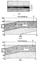
- the optimal welding parameters are shown on the basis of graphic representations, in which polyolefin sheets or foils can be welded.
- 8 shows the welding of two polyolefin webs which had been stored outdoors for ten days prior to welding.
- the stored polyolefin sheets were welded on the basis of the welding parameters shown in Table 1 below, the subsequent peeling tests giving the area 51 marked black.
- the welding was carried out in the temperature ranges given in Table 1 at three different speeds of the welding machine by means of a hot air nozzle, shown in FIGS. 5a to 5d and Fig. 6.
- the temperature relates to that of the hot air emerging from the nozzle.
- the welding seams were checked both by hand and using tensile testing machines. The measured values are also shown in Table 1.
- FIGS. 8 and 9 show, analogously to this, the processing area 51 during the welding of polyolefin films which have been stored for 14 days, respectively. were exposed to the weather. It clearly shows that the areas 51 of the two FIGS. 8 and 9 are essentially the same. The values shown in Tables 1 and 2 are also essentially congruent.
- Hot air nozzles are of course only exemplary embodiments, which serve to better the invention explain. Of course it is possible to change these nozzles, to modify or add further elements within the scope of the protection claims 1 and 9.
- friction rollers or friction rollers a kind of washers to use, which in turn lined up on a Brackets are arranged.
- very small steel brush rollers and the like is conceivable.
- the hot air broadly depending on the surface of the two to be welded Blown plastic films. It is essential that before pressing during the welding process of the two foils or Plastic sheets are sanded or roughened.
Description
- Fig. 1
- in Frontansicht, schematisch einen Schweissautomaten, beispielsweise bekannt aus der CH 677 898,
- Fig. 2
- den Schweissautomaten aus Fig. 1 in Ansicht von oben,
- Fig. 3
- in Perspektive, eine Heissluftdüse, beispielsweise bekannt aus der CH 677 898,
- Fig. 4a bis 4d
- eine Ausführungsvariante einer erfindungsgemässen Heissluftdüse,
- Fig. 5a bis 5d
- eine weitere Ausführungsvariante der erfindungsgemässen Heissluftdüse,
- Fig. 6
- wiederum eine weitere Ausführungsvariante einer erfindungsgemässen Heissluftdüse,
- Fig. 7
- im Schnitt, eine Schweissnaht zweier erfindungsgemäss miteinander verschweisster Kunststoffbahnen und
- Fig. 8 und 9
- grafisch dargestellt, die idealen Geräteeinstellparameter, um Folien mittels einer erfindungsgemässen Vorrichtung miteinander zu verschweissen.


Claims (9)
- Vorrichtung zum Verschweissen von Folien bzw. Kunststoffbahnen, aufweisend eine Heisslufterzeugung sowie eine für die Ausgabe der Heissluft vorzugsweise eine schlitzartige Öffnung (27) aufweisende Düse (23), vorgesehen, um die Heissluft zwischen zwei zu verschweissende Folien bzw. Kunststoffbahnen (3, 5) einzublasen, mit mindestens einer rollen- oder walzenartigen Schleifeinrichtung (41), welche an der vorzugsweise schlitzartigen Düse bzw. Öffnung (27) vorgelagert bzw. dieser in Bearbeitungsrichtung nachgeschaltet ist, um die zu verschweissenden Oberflächen der Folien bzw. Bahnen vor dem Zusammenpressen anzuschleifen oder aufzurauhen, dadurch gekennzeichnet, daß im Bereich der Düse bzw. der Öffnung nach oben und/oder nach unten vorstehende Leitoder Schleifbleche (33, 35) vorgesehen sind, entlang welcher die zu verschweissenden Kunststoffbahnen vor dem Schweissen entlanggeführt werden bzw. entlangschleifen.
- Vorrichtung nach Anspruch 1, dadurch gekennzeichnet, dass die Walze (41) aus mehreren nebeneinander gereihten, zylinderartigen Rollen oder Walzen (43) besteht, welche auf einem an der Öffnung (27) oder am Heissluftzufuhrkörper (29) angehängten, klammerartigen Halte- bzw. Querstab (45) aufgereiht sind.
- Vorrichtung nach Anspruch 2, dadurch gekennzeichnet, dass die Rollen oder Walzen (43) eine aufgerauhte Oberfläche aufweisen und je die mittige Haltebohrung (44) exzentrisch ausgebildet ist, damit bei unebener oder unegaler Auflage sich die Rollen oder Walzen dieser anpassen können.
- Vorrichtung nach einem der Ansprüche 1 bis 3, dadurch gekennzeichnet, dass die Schleifwalze (41) weiter einen seitlich von der Unterlagefolie (3) wegverlaufenden, die obere, mit der Unterlage-Folie zu verbindende Folie (5) aussen umgreifenden Führungsbügel (49) aufweist, um die obere Folie (5) gegen die Schleifwalze zu führen bzw. auf dieser zu halten.
- Vorrichtung nach einem der Ansprüche 1 bis 4, dadurch gekennzeichnet, dass an der Schleifwalze (41) Mittel (48) vorgesehen sind, um ein Aufwärts- ober Abwärts-Auslenken in bezug auf die schlitzartige Öffnung (27) zu begrenzen.
- Vorrichtung nach Anspruch 1, dadurch gekennzeichnet, dass federartige Lamellen (33, 35) von der Düse bzw. von der vorzugsweise schlitzartigen Öffnung (27) nach unten bzw. nach oben vorstehen, wobei quer zur Richtung der auszublasenden Heissluft mehrere Lamellen nebeneinander angeordnet sind, derart, dass sie sich je der Kontur der anzuschleifenden Oberfläche der Folie bzw. Kunststoffbahn anpassen kann.
- Vorrichtung nach einem der Ansprüche 1 bis 6, dadurch gekennzeichnet, dass an der Düse, der vorzugsweise schlitzartigen Öffnung (27) vorgeschaltet, Perforierungen oder Kleinstlochungen (31) im Heissluftzufuhrkanal bzw. -körper (29) vorgesehen sind, um die beiden zu verbindenden Folienoberflächen vorzuwärmen.
- Vorrichtung nach einem der Ansprüche 1 bis 7, dadurch gekennzeichnet, dass in Verarbeitungsrichtung nachfolgend an die Öffnung für die Ausgabe für die Heissluft mindestens eine Anpressrolle (25) vorgesehen ist, vorzugsweise zwei Anpressrollen (25).
- Verfahren zum Verschweissen von Folien bzw. Kunststoffbahnen mittels einer Vorrichtung nach einem der Ansprüche 1 bis 8, dadurch gekennzeichnet, dass vor oder beim Verschweissen mittels Heissluft je die Oberfläche der beiden miteinander zu verbindenden Folien bzw. Kunststoffbahnen angeschliffen bzw. angerauht werden.
Applications Claiming Priority (3)
| Application Number | Priority Date | Filing Date | Title |
|---|---|---|---|
| CH56198 | 1998-03-09 | ||
| CH56198 | 1998-03-09 | ||
| CH561/98 | 1998-03-09 |
Publications (3)
| Publication Number | Publication Date |
|---|---|
| EP0914935A2 EP0914935A2 (de) | 1999-05-12 |
| EP0914935A3 EP0914935A3 (de) | 1999-07-14 |
| EP0914935B1 true EP0914935B1 (de) | 2001-05-23 |
Family
ID=4189866
Family Applications (1)
| Application Number | Title | Priority Date | Filing Date |
|---|---|---|---|
| EP98123347A Expired - Lifetime EP0914935B1 (de) | 1998-03-09 | 1998-12-08 | Vorrichtung zum Verschweissen von Kunststoffbahnen |
Country Status (2)
| Country | Link |
|---|---|
| EP (1) | EP0914935B1 (de) |
| DE (1) | DE59800751D1 (de) |
Cited By (1)
| Publication number | Priority date | Publication date | Assignee | Title |
|---|---|---|---|---|
| DE202017106063U1 (de) | 2017-10-06 | 2018-01-24 | Leister Technologies Ag | Kontaktschweißheizkomponente und Schweißautomat |
Families Citing this family (6)
| Publication number | Priority date | Publication date | Assignee | Title |
|---|---|---|---|---|
| EP1254759B1 (de) * | 2001-05-03 | 2009-03-18 | Leister Process Technologies | Düse zum Schweissen von Kunststoffbahnen oder -folien |
| EP1358993B1 (de) * | 2002-04-29 | 2009-12-30 | Sika Technology AG | Vorrichtung zum Verschweissen von Kunststoffbahnen |
| CH698082B1 (de) * | 2005-05-04 | 2009-05-15 | Sika Technology Ag | Düsen-Vorsatz für eine Heissluftdüse zum Warmgasschweissen von Kunststoffbahnen. |
| EP1884347A1 (de) * | 2006-08-04 | 2008-02-06 | Sika Technology AG | Vorrichtung zum Verschweissen von Kunststoffbahnen |
| GB2528289A (en) | 2014-07-16 | 2016-01-20 | Kraft Foods R&D Inc | A die-cut lid and associated container and method |
| CN113334777A (zh) * | 2021-06-07 | 2021-09-03 | 南京度锐新材料科技有限公司 | 一种高分子材料刮刀用生产线 |
Family Cites Families (2)
| Publication number | Priority date | Publication date | Assignee | Title |
|---|---|---|---|---|
| DE3520682A1 (de) * | 1985-06-10 | 1987-01-22 | Munsch Chemie Pumpen Gmbh | Schweissgeraet |
| JPH0717015B2 (ja) * | 1991-01-28 | 1995-03-01 | 積水化成品工業株式会社 | 発泡体の積層方法 |
-
1998
- 1998-12-08 DE DE59800751T patent/DE59800751D1/de not_active Expired - Fee Related
- 1998-12-08 EP EP98123347A patent/EP0914935B1/de not_active Expired - Lifetime
Cited By (2)
| Publication number | Priority date | Publication date | Assignee | Title |
|---|---|---|---|---|
| DE202017106063U1 (de) | 2017-10-06 | 2018-01-24 | Leister Technologies Ag | Kontaktschweißheizkomponente und Schweißautomat |
| WO2019068574A1 (de) | 2017-10-06 | 2019-04-11 | Leister Technologies Ag | KONTAKTSCHWEIßHEIZKOMPONENTE UND SCHWEIßAUTOMAT |
Also Published As
| Publication number | Publication date |
|---|---|
| EP0914935A3 (de) | 1999-07-14 |
| DE59800751D1 (de) | 2001-06-28 |
| EP0914935A2 (de) | 1999-05-12 |
Similar Documents
| Publication | Publication Date | Title |
|---|---|---|
| DE4018074C2 (de) | Vorrichtung zum Reinigen eines umlaufenden Papiermaschinensiebes | |
| DE3927254A1 (de) | Verfahren und spinnduesenaggregat fuer die herstellung von kunststoff-faeden und/oder kunststoff-fasern im zuge der herstellung von einem spinnvlies aus thermoplastischem kunststoff | |
| WO2003016601A1 (de) | Vorrichtung zur herstellung von fasern in einem elektrostatischen spinnverfahren | |
| EP0914935B1 (de) | Vorrichtung zum Verschweissen von Kunststoffbahnen | |
| DE1901149A1 (de) | Filterspuelgeraet | |
| EP3676079B1 (de) | Kontaktschweissheizkomponente und schweissautomat | |
| CH654522A5 (de) | Verfahren und vorrichtung zum zusammenschweissen von oberflaechen thermoplastischen materials. | |
| EP1358993B1 (de) | Vorrichtung zum Verschweissen von Kunststoffbahnen | |
| DE1546312A1 (de) | Einrichtung zum Beschichten laufender Papierbahnen | |
| DE102004044399A1 (de) | Schmiermittelsäuberungsvorrichtung fürs Trockendrahtziehen | |
| EP0652411B1 (de) | Vorrichtung zum Entfernen von Oberflächenwasser an Kunststoffsträngen | |
| DE602004011323T2 (de) | Abdeckmaterial für dächer | |
| DE102006053801A1 (de) | Lötdüse zum Wellenlöten von Leiterplatten | |
| DE3217805A1 (de) | Formationsspritzrohr zur erzeugung von turbulenzenergie in einer suspension bei der karton- oder papierherstellung, sowie verfahren zur herstellung eines solchen formationsspritzrohres | |
| EP1254759B1 (de) | Düse zum Schweissen von Kunststoffbahnen oder -folien | |
| DE1254853B (de) | Verfahren und Vorrichtung zum Aufbringen einer Klebstoffschicht auf Platten- oder Bahnmaterial bei der Herstellung von Sperrholz oder anderen Schichtmaterialien | |
| EP2049322A1 (de) | Vorrichtung zum verschweissen von kunststoffbahnen | |
| DE19604904A1 (de) | Vorrichtung zum Trennschweißen einer Kunststoffolienbahn bei der Herstellung von Beuteln, Taschen oder dergleichen | |
| DE19726078A1 (de) | Maschine zum Lackieren oder Einfärben von Werkstücken | |
| EP0010747B1 (de) | Vorrichtung zum Filtern von Feststoffe enthaltenden Flüssigkeiten | |
| WO2006117397A1 (de) | Düsen-vorsatz für eine vorrichtung zum warmgasschweissen von kunststoffbahnen | |
| DE2402805B2 (de) | Verfahren zur selbsttätigen Reinigung einer der Schmutzabscheidung dienenden Filteranordnung und Vorrichtung zur Durchführung des Verfahrens | |
| EP2087159A1 (de) | Verfahren zum verhindern des verklebens von vliesmaterial beim bonding-prozess und vorrichtung zum verhindern des verklebens von vliesmaterial beim bonding-prozess | |
| DE1914238C (de) | Verfahren zum Zuschneiden von Stof fen, insbesondere von Kleiderstoffen oder anderen textlien Flachengebilden, durch Zerstören der Fasern in den Schnitt linien mittels Sauren oder Laugen | |
| DE4443842A1 (de) | Verbindung für Blechränder sowie Verfahren und Vorrichtung hierzu |
Legal Events
| Date | Code | Title | Description |
|---|---|---|---|
| PUAI | Public reference made under article 153(3) epc to a published international application that has entered the european phase |
Free format text: ORIGINAL CODE: 0009012 |
|
| AK | Designated contracting states |
Kind code of ref document: A2 Designated state(s): CH DE LI |
|
| AX | Request for extension of the european patent |
Free format text: AL;LT;LV;MK;RO;SI |
|
| PUAL | Search report despatched |
Free format text: ORIGINAL CODE: 0009013 |
|
| 17P | Request for examination filed |
Effective date: 19990424 |
|
| AK | Designated contracting states |
Kind code of ref document: A3 Designated state(s): AT BE CH CY DE DK ES FI FR GB GR IE IT LI LU MC NL PT SE |
|
| AX | Request for extension of the european patent |
Free format text: AL;LT;LV;MK;RO;SI |
|
| AKX | Designation fees paid |
Free format text: CH DE LI |
|
| GRAG | Despatch of communication of intention to grant |
Free format text: ORIGINAL CODE: EPIDOS AGRA |
|
| 17Q | First examination report despatched |
Effective date: 20000821 |
|
| GRAG | Despatch of communication of intention to grant |
Free format text: ORIGINAL CODE: EPIDOS AGRA |
|
| GRAH | Despatch of communication of intention to grant a patent |
Free format text: ORIGINAL CODE: EPIDOS IGRA |
|
| GRAH | Despatch of communication of intention to grant a patent |
Free format text: ORIGINAL CODE: EPIDOS IGRA |
|
| GRAA | (expected) grant |
Free format text: ORIGINAL CODE: 0009210 |
|
| AK | Designated contracting states |
Kind code of ref document: B1 Designated state(s): CH DE LI |
|
| REG | Reference to a national code |
Ref country code: CH Ref legal event code: NV Representative=s name: TROESCH SCHEIDEGGER WERNER AG Ref country code: CH Ref legal event code: EP |
|
| REF | Corresponds to: |
Ref document number: 59800751 Country of ref document: DE Date of ref document: 20010628 |
|
| PLBE | No opposition filed within time limit |
Free format text: ORIGINAL CODE: 0009261 |
|
| STAA | Information on the status of an ep patent application or granted ep patent |
Free format text: STATUS: NO OPPOSITION FILED WITHIN TIME LIMIT |
|
| 26N | No opposition filed | ||
| PGFP | Annual fee paid to national office [announced via postgrant information from national office to epo] |
Ref country code: DE Payment date: 20031218 Year of fee payment: 6 |
|
| REG | Reference to a national code |
Ref country code: CH Ref legal event code: NV Representative=s name: HANS ULRICH SEIFERT SEIFERT & PARTNER |
|
| PG25 | Lapsed in a contracting state [announced via postgrant information from national office to epo] |
Ref country code: DE Free format text: LAPSE BECAUSE OF NON-PAYMENT OF DUE FEES Effective date: 20050701 |
|
| PGFP | Annual fee paid to national office [announced via postgrant information from national office to epo] |
Ref country code: CH Payment date: 20171204 Year of fee payment: 20 |
|
| REG | Reference to a national code |
Ref country code: CH Ref legal event code: PL |