EP0912386B1 - Vorrichtung zur verriegelung einer verstellbaren lenksäule, insbesondere für kraftfahrzeuge - Google Patents
Vorrichtung zur verriegelung einer verstellbaren lenksäule, insbesondere für kraftfahrzeuge Download PDFInfo
- Publication number
- EP0912386B1 EP0912386B1 EP97932731A EP97932731A EP0912386B1 EP 0912386 B1 EP0912386 B1 EP 0912386B1 EP 97932731 A EP97932731 A EP 97932731A EP 97932731 A EP97932731 A EP 97932731A EP 0912386 B1 EP0912386 B1 EP 0912386B1
- Authority
- EP
- European Patent Office
- Prior art keywords
- clamping
- steering column
- clamping elements
- operating rod
- guide slots
- Prior art date
- Legal status (The legal status is an assumption and is not a legal conclusion. Google has not performed a legal analysis and makes no representation as to the accuracy of the status listed.)
- Expired - Lifetime
Links
- 238000006073 displacement reaction Methods 0.000 claims 2
- 208000027418 Wounds and injury Diseases 0.000 description 2
- 230000006378 damage Effects 0.000 description 2
- 208000014674 injury Diseases 0.000 description 2
- 241000047428 Halter Species 0.000 description 1
- 230000009286 beneficial effect Effects 0.000 description 1
- 238000011161 development Methods 0.000 description 1
- 230000018109 developmental process Effects 0.000 description 1
- 238000004519 manufacturing process Methods 0.000 description 1
- 230000000007 visual effect Effects 0.000 description 1
Images

Classifications
-
- B—PERFORMING OPERATIONS; TRANSPORTING
- B62—LAND VEHICLES FOR TRAVELLING OTHERWISE THAN ON RAILS
- B62D—MOTOR VEHICLES; TRAILERS
- B62D1/00—Steering controls, i.e. means for initiating a change of direction of the vehicle
- B62D1/02—Steering controls, i.e. means for initiating a change of direction of the vehicle vehicle-mounted
- B62D1/16—Steering columns
- B62D1/18—Steering columns yieldable or adjustable, e.g. tiltable
- B62D1/184—Mechanisms for locking columns at selected positions
-
- Y—GENERAL TAGGING OF NEW TECHNOLOGICAL DEVELOPMENTS; GENERAL TAGGING OF CROSS-SECTIONAL TECHNOLOGIES SPANNING OVER SEVERAL SECTIONS OF THE IPC; TECHNICAL SUBJECTS COVERED BY FORMER USPC CROSS-REFERENCE ART COLLECTIONS [XRACs] AND DIGESTS
- Y10—TECHNICAL SUBJECTS COVERED BY FORMER USPC
- Y10T—TECHNICAL SUBJECTS COVERED BY FORMER US CLASSIFICATION
- Y10T403/00—Joints and connections
- Y10T403/32—Articulated members
- Y10T403/32254—Lockable at fixed position
- Y10T403/32532—Clamped members
-
- Y—GENERAL TAGGING OF NEW TECHNOLOGICAL DEVELOPMENTS; GENERAL TAGGING OF CROSS-SECTIONAL TECHNOLOGIES SPANNING OVER SEVERAL SECTIONS OF THE IPC; TECHNICAL SUBJECTS COVERED BY FORMER USPC CROSS-REFERENCE ART COLLECTIONS [XRACs] AND DIGESTS
- Y10—TECHNICAL SUBJECTS COVERED BY FORMER USPC
- Y10T—TECHNICAL SUBJECTS COVERED BY FORMER US CLASSIFICATION
- Y10T74/00—Machine element or mechanism
- Y10T74/20—Control lever and linkage systems
- Y10T74/20576—Elements
- Y10T74/20636—Detents
- Y10T74/2066—Friction
Definitions
- the invention relates to a device for locking an adjustable steering column according to the generic term of claim 1.
- Such a device is from DE 39 25 706 C1 known in which to lock the pivotable Steering column with a clamping device axially on a Actuating rod arranged eccentric element is provided is.
- a clamping device axially on a Actuating rod arranged eccentric element is provided is.
- the present invention is based on the object a device for locking an adjustable Steering column according to the preamble of claim 1 create which with reduced constructive and manufacturing technology Effort is compact. Furthermore, in the event of an accident, the risk of injury reduced or avoided by the actuators become.
- the main advantages achieved with the invention consist in that the clamping elements of the clamping device are relatively simple, with the lock or unlocking the steering column provided operating rod axially immovable relative to the steering column and compact in one security cheap and little used space is arranged. Due to the sliding mounting of the operating rod in the holes of the clamping elements as well as in the guide slots guided clamping elements can the steering column stepless and comfortable in the high and Longitudinal direction can be adjusted.
- Another significant advantage of the invention Device is that with the operating rod connected operating lever easy to use positioned near the steering wheel and one at the free end the handle provided as part of the operating lever a steering lock recess for the ignition key is. This can result in an accident Risk of injury from the operating rod or the Actuation lever can be significantly reduced.
- the device 1 shown in Fig. 1 consists essentially from one with the vehicle body 8 to one connected manner not shown and two parallel and vertically aligned support parts 3, 3a having steering column bracket 4 and an approximately U-shaped Holder 7 with two also parallel and vertical aligned legs 5, 5a, the free ends with a casing tube 6 of the steering column 2 are welded.
- the steering column 2 can be in the set position one the holder 7 between the support parts 3, 3a jamming clamping device 9 can be locked.
- FIG. 3 illustrates, on the respective support parts 3, 3a approximately Guide slots running perpendicular to the steering column 2 11, 11a and on the respective legs 5, 5a approximately guide slots arranged axially parallel to the steering column 2 12, 12a provided.
- the neighboring ones Guide slots 11, 12; 11a, 12a are crossed arranged and thus form a backdrop for two arranged braced in the vehicle transverse direction Clamping elements 10, 10a (FIG. 1) of the clamping device 9.
- the clamping elements 10, 10a are in the form of a cylinder-piston unit with a cylindrical part 14 on the clamping element 10a and a piston part 13 on the clamping element 10 formed, the piston part 13 in the cylindrical Part 14 is axially slidably received.
- the clamping elements 10, 10a are each with one end through the guide slots 11, 12; 11a, 12a and lie on the outside, each with a headboard 15, 15a on the corresponding support parts 3, 3a.
- the Head part 15a is by a nut 16 and one arranged between the nut 16 and the support part 3a Disc 17 formed, which on an axially on the cylindrical Part 14 arranged threaded shaft 18 mounted are.
- the steering column 2 is therefore on the one hand (for height adjustment) together with the clamping elements 10, 10a in the approximately vertical slot guides 11, 11a and on the other (for longitudinal adjustment) using the approximately horizontal arranged guide slots 12, 12a on the Clamping elements 10, 10a slidably mounted.
- FIG. 8 An alternative embodiment of the clamping device 9 is shown in Fig. 8. This version is on the cylindrical Part 14 of the clamping element 10a an axially arranged threaded bore 31 is provided in the Threaded shaft 32 is screwed. The threaded shaft 32 is formed in one piece with the head part 15a.
- the clamping elements 10, 10a have accordingly on the piston part 13 and on the cylindrical part 14 in each case a bore 19, 19a, which is axially parallel to the steering column 2 and are partially covered.
- the both holes 19, 19a also pass through axially parallel to the steering column 2 arranged operating rod 20 with an oval cross section 21.
- the actuating rod 20 is at one end in the area near the steering wheel a steering lock housing 28 (Fig. 6) rotatable, however axially immovable and at the other end, as in Fig. 2nd shown, slidably mounted in the holes 19, 19a, so that when adjusting the steering column 2, the location of the Maintain operating rod 20 opposite the steering column 2 becomes.
- FIG. 4 and 5 is the clamping of the clamping elements 10, 10a illustrated by means of the actuating rod 20.
- Fig. 4 in the unlocked state largest diameter of the actuating rod 20 in the area of the oval cross section 21 aligned approximately vertically, whereby the clamping elements 10, 10a each in one furthest from each other.
- the bores are in this position of the actuating rod 20 19, 19a of the clamping elements 10, 10a about half covers and the head parts 15, 15a (Fig. 1 and 8) the clamping elements 10, 10a are applied without pretension the corresponding support parts 3, 3a.
- an actuating lever 25 is provided at the end of the actuating rod 20 near the steering wheel, as shown in FIG Arranged locking device 27 audibly and noticeably engages.
- the latching device 27 consists of elastic spring elements which are known per se and therefore not shown in more detail, and which partially wrap around the actuating lever 25, which at least in this area is designed as a round rod, in a non-positive and / or positive manner.
- the position of the actuating lever 25 in the unlocked position is indicated in simplified form by a dash-dotted line Z.
- a handle 26 is provided, which is in the locked position, as in Fig. 7 shown in a recess 30 on a Steering lock recess 29 is located.
- the handle 26 at reached the adjustment of the steering column 2 very cheap and be operated.
Landscapes
- Engineering & Computer Science (AREA)
- Chemical & Material Sciences (AREA)
- Combustion & Propulsion (AREA)
- Transportation (AREA)
- Mechanical Engineering (AREA)
- Steering Controls (AREA)
- Steering Devices For Bicycles And Motorcycles (AREA)
Description
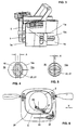
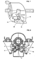
- Fig. 1
- einen Querschnitt durch die erfindungsgemäße Vorrichtung im Bereich der Klemmelemente;
- Fig. 2
- einen Längsschnitt durch die Vorrichtung gemäß Fig. 1;
- Fig. 3
- eine räumliche Ansicht des Lenksäulenträgers und des Halters der Lenksäule vor der Montage der Klemmelemente;
- Fig. 4 und Fig. 5
- die Wirkungsweise der Klemmeinrichtung der Vorrichtung gemäß Fig. 1;
- Fig. 6
- eine Ansicht der Lenksäule gemäß Pfeil X in Fig. 2;
- Fig. 7
- eine räumliche Ansicht des lenkradnahen Bereiches der Lenksäule gemäß Pfeil Y in Fig. 6;
- Fig. 8
- einen Querschnitt gemäß Fig. 1, jedoch mit einer alternativen Ausbildung der Klemmelemente.
Claims (15)
- Vorrichtung zur Verriegelung einer verstellbaren Lenksäule, insbesondere für Kraftfahrzeuge, welche zwischen zwei Tragteilen des Fahrzeugaufbaus in Führungsschlitzen längs- und/oder höhenverstellbar angeordnet und mittels einer Klemmeinrichtung zum Fahrzeugaufbau verriegelbar ist, wobei die Klemmeinrichtung zwei mittels einer axial verdrehbaren Betätigungsstange verspannbare Klemmelemente aufweist, dadurch gekennzeichnet, daß die Klemmelemente (10, 10a) jeweils eine senkrecht zur Klemmbewegung (F1, F2) verlaufende Bohrung (19, 19a) aufweisen, welche parallel zueinander und teilweise überdeckend angeordnet sowie mit der einen ellipsen- bzw. ovalförmigen Querschnitt (21) aufweisenden Betätigungsstange (20) durchsetzt sind.
- Vorrichtung nach Anspruch 1, dadurch gekennzeichnet, daß zumindest der ellipsen- bzw. ovalförmige Bereich der Betätigungsstange (20) sowie die Bohrungen (19, 19a) an den Klemmelementen (10, 10a) - in Draufsicht und/oder Seitensicht gesehen - parallel zur Lenksäule (2) angeordnet sind.
- Vorrichtung nach Anspruch 1 oder 2, dadurch gekennzeichnet, daß die Lenksäule (2) einen zwischen den Tragteilen (3, 3a) angeordneten U-förmigen Halter (7) mit zwei parallel zueinander und vertikal ausgerichteten Schenkeln (5, 5a) aufweist.
- Vorrichtung nach einem der Ansprüche 1 bis 3, dadurch gekennzeichnet, daß die Führungsschlitze (11, 11a) für die Höhenverstellung der Lenksäule (2) an den Tragteilen (3, 3a) und die Führungsschlitze (12, 12a) für die Längsverstellung an den Schenkeln (5, 5a) ausgebildet sind, wobei die Führungsschlitze (11, 11a) zur Lenksäule (2) etwa achsparallel und die Führungsschlitze (12, 12a) etwa senkrecht zur Lenksäule (2) angeordnet sind.
- Vorrichtung nach einem der Ansprüche 1 bis 4, dadurch gekennzeichnet, daß die Klemmelemente (10, 10a) jeweils mit einem Ende durch die Führungsschlitze (11, 12; 11a, 12a) durchgeführt sind und außenseitig mit jeweils einem Kopfteil (15, 15a) an den Tragteilen (3, 3a) anliegen.
- Vorrichtung nach einem der Ansprüche 1 bis 5, dadurch gekennzeichnet, daß die Klemmelemente (10, 10a) im Bereich der Bohrungen (19, 19a) teilweise überdeckend in- oder hintereinandergreifen und zueinander verschiebbar ausgebildet sind.
- Vorrichtung nach Anspruch 6, dadurch gekennzeichnet, daß die Klemmelemente (10, 10a) in Form einer Zylinder-Kolben-Einheit mit einem zylindrischen Teil (14) am Klemmelement (10a) und einem Kolbenteil (13) am Klemmelement (10) ausgebildet sind, wobei das Kolbenteil (13) im zylindrischen Teil (14) axial verschiebbar aufgenommen ist.
- Vorrichtung nach einem der Ansprüche 1 bis 7, dadurch gekennzeichnet, daß die Bohrungen (19, 19a) sowie der ellipsen- bzw. ovalförmige Bereich der Betätigungsstange (20) zwischen den Schenkeln (5, 5a) angeordnet sind.
- Vorrichtung nach einem der Ansprüche 1 bis 8, dadurch gekennzeichnet, daß die Betätigungsstange (20) an der Lenksäule (2) verdrehbar, aber axial unverschiebbar gelagert und im nichtverriegelten Zustand längsverschiebbar in den Bohrungen (19, 19a) der Klemmelemente (10, 10a) geführt ist.
- Vorrichtung nach einem der Ansprüche 1 bis 9, dadurch gekennzeichnet, daß zum Verdrehen der Betätigungsstange (20) zwischen der verriegelten und der entriegelten Stellungen am von den Klemmelementen (10, 10a) abgekehrten Ende der Betätigungsstange (20) ein etwa rechtwinkliger Betätigungshebel (25) mit einem Griff (26) vorgesehen ist.
- Vorrichtung nach einem der Ansprüche 1 bis 10, dadurch gekennzeichnet, daß die Lenksäule (2) eine Lenkschloßmulde (29) mit einer Aussparung (30) für den Griff (26) aufweist, wobei an der Lenkschloßmulde (29) bzw. einem Lenkschloßgehäuse (28) eine Rastvorrichtung (27) zum akustischen und/oder fühlbaren Markieren der verriegelten Stellung der Betätigungsstange (20) bzw. des Betätigungshebels (25) vorgesehen ist.
- Vorrichtung nach einem der Ansprüche 1 bis 11, dadurch gekennzeichnet, daß zum Justieren der Klemmeinrichtung (9) zumindest ein Klemmelement (10a) mit einem in Richtung der Klemmbewegung (F1, F2) verstellbaren Kopfteil (15a) ausgebildet ist.
- Vorrichtung nach Anspruch 12, dadurch gekennzeichnet, daß das Kopfteil (15a) mit einem in eine Gewindebohrung (31) am Klemmelement (10a) eindrehbaren Gewindeschaft (32) ausgebildet und mittels einer Mutter (33) am Klemmelement (10a) fixierbar ist.
- Vorrichtung nach Anspruch 12, dadurch gekennzeichnet, daß das Klemmelement (10a) am freien Ende mit einem Gewindeschaft (34) ausgebildet und das Kopfteil (15a) durch eine am Gewindeschaft (34) montierte Mutter (35) gebildet ist, wobei zwischen der Mutter (35) und dem Tragteil (3a) eine Scheibe (36) vorgesehen ist.
- Vorrichtung nach einem der Ansprüche 1 bis 14, dadurch gekennzeichnet, daß auf den Klemmelementen (10, 10a) zwischen den jeweiligen Tragteilen (3, 3a) und den jeweiligen Schenkeln (5, 5a) im Bereich der sich kreuzenden Führungsschlitze 11, 12; 11a, 12a) jeweils eine Führungsscheibe (22, 22a) vorgesehen ist.
Applications Claiming Priority (3)
| Application Number | Priority Date | Filing Date | Title |
|---|---|---|---|
| DE19629246A DE19629246A1 (de) | 1996-07-19 | 1996-07-19 | Vorrichtung zur Verriegelung einer verstellbaren Lenksäule, insbesondere für Kraftfahrzeuge |
| DE19629246 | 1996-07-19 | ||
| PCT/DE1997/001401 WO1998003386A1 (de) | 1996-07-19 | 1997-07-03 | Vorrichtung zur verriegelung einer verstellbaren lenksäule, insbesondere für kraftfahrzeuge |
Publications (2)
| Publication Number | Publication Date |
|---|---|
| EP0912386A1 EP0912386A1 (de) | 1999-05-06 |
| EP0912386B1 true EP0912386B1 (de) | 2000-03-15 |
Family
ID=7800328
Family Applications (1)
| Application Number | Title | Priority Date | Filing Date |
|---|---|---|---|
| EP97932731A Expired - Lifetime EP0912386B1 (de) | 1996-07-19 | 1997-07-03 | Vorrichtung zur verriegelung einer verstellbaren lenksäule, insbesondere für kraftfahrzeuge |
Country Status (10)
| Country | Link |
|---|---|
| US (1) | US5992263A (de) |
| EP (1) | EP0912386B1 (de) |
| JP (1) | JP4001923B2 (de) |
| KR (1) | KR100547733B1 (de) |
| AU (1) | AU3619097A (de) |
| BR (1) | BR9710380A (de) |
| CZ (1) | CZ291318B6 (de) |
| DE (2) | DE19629246A1 (de) |
| ES (1) | ES2145619T3 (de) |
| WO (1) | WO1998003386A1 (de) |
Families Citing this family (19)
| Publication number | Priority date | Publication date | Assignee | Title |
|---|---|---|---|---|
| US6516640B2 (en) | 2000-12-05 | 2003-02-11 | Strattec Security Corporation | Steering column lock apparatus and method |
| US6571587B2 (en) * | 2001-01-09 | 2003-06-03 | Strattec Security Corporation | Steering column lock apparatus and method |
| AU2003211225A1 (en) * | 2002-04-17 | 2003-10-27 | Nsk Ltd. | Method of assembling steering columns |
| AU2003252690A1 (en) | 2002-07-25 | 2004-02-16 | Nsk Ltd. | Steering column device |
| EP1547902A4 (de) * | 2002-09-04 | 2006-11-29 | Nsk Ltd | Lenksäulenvorrichtung der fahrzeugpositionseinstellungsart |
| US20040123695A1 (en) * | 2002-10-15 | 2004-07-01 | Knott Jeffrey A. | Steering wheel tilt mechanism |
| JP4354762B2 (ja) * | 2003-09-01 | 2009-10-28 | 日本精工株式会社 | 車両用位置調整式ステアリングコラム装置 |
| US7178832B2 (en) * | 2004-01-06 | 2007-02-20 | Delphi Technologies, Inc. | Telescoping steering column assembly with brake |
| US7140213B2 (en) * | 2004-02-21 | 2006-11-28 | Strattec Security Corporation | Steering column lock apparatus and method |
| US20050200111A1 (en) * | 2004-03-11 | 2005-09-15 | Cymbal William D. | Multi piece bearing for telescoping steering column assembly |
| US7516985B2 (en) * | 2004-03-11 | 2009-04-14 | Delphi Technologies, Inc. | Multi piece bearing for telescoping steering column assembly |
| JP2007168625A (ja) * | 2005-12-22 | 2007-07-05 | Fuji Kiko Co Ltd | ステアリング装置 |
| DE102006056582A1 (de) | 2006-11-29 | 2008-06-05 | Thyssenkrupp Presta Ag | Lenksäule für ein Kraftfahrzeug |
| ATE524367T1 (de) * | 2008-05-16 | 2011-09-15 | Zf Systemes De Direction Nacam Sas | Vorrichtung zur einstellung der position einer lenksäule in einem kraftfahrzeug |
| JP2012131253A (ja) * | 2010-12-20 | 2012-07-12 | Caterpillar Sarl | 建設機械におけるチルトステアリング装置 |
| JP5603783B2 (ja) * | 2011-01-06 | 2014-10-08 | 株式会社ジェイテクト | ステアリング装置 |
| JP5614290B2 (ja) * | 2011-01-06 | 2014-10-29 | 株式会社ジェイテクト | ステアリング装置 |
| US10046789B2 (en) * | 2015-05-19 | 2018-08-14 | Nsk Ltd. | Telescopic steering device |
| KR20180071813A (ko) | 2016-12-20 | 2018-06-28 | 이래에이엠에스 주식회사 | 스위치모듈을 포함하는 핸들락 시스템 및 이를 제어하는 방법 |
Family Cites Families (11)
| Publication number | Priority date | Publication date | Assignee | Title |
|---|---|---|---|---|
| US3387865A (en) * | 1966-08-29 | 1968-06-11 | Northrop Corp | Drill string concept |
| DE3016212A1 (de) * | 1980-04-26 | 1981-10-29 | Volkswagenwerk Ag, 3180 Wolfsburg | Laengen- und neigungsverstellbare lenksaeule fuer ein fahrzeug |
| JPH028864Y2 (de) * | 1981-03-04 | 1990-03-02 | ||
| DE3920783C2 (de) * | 1989-06-24 | 1995-06-01 | Bayerische Motoren Werke Ag | Vorrichtung zum Längs- und Höhenverstellen der Lenksäule eines Kraftfahrzeugs |
| DE3925706C1 (de) * | 1989-08-03 | 1991-01-31 | Dr.Ing.H.C. F. Porsche Ag, 7000 Stuttgart, De | |
| SE465563B (sv) * | 1989-10-31 | 1991-09-30 | Volvo Ab | Justerbar fordonsratt |
| US5257813A (en) * | 1992-09-23 | 1993-11-02 | Chrysler Corp | Steering column tilt assist |
| GB2273338A (en) * | 1992-12-02 | 1994-06-15 | Torrington Co | Steering column clamping mechanism. |
| EP0667461B1 (de) * | 1994-02-09 | 1997-05-28 | Pcm Willen S.A. | Präzisionsbefestigung zwischen zwei Teilen |
| US5555772A (en) * | 1994-10-31 | 1996-09-17 | General Motors Corporation | Position control apparatus for steering column |
| GB2295663A (en) * | 1994-12-01 | 1996-06-05 | Torrington Co | Clamping mechanism for an adjustable steering column |
-
1996
- 1996-07-19 DE DE19629246A patent/DE19629246A1/de not_active Withdrawn
-
1997
- 1997-06-23 US US08/880,715 patent/US5992263A/en not_active Expired - Fee Related
- 1997-07-03 AU AU36190/97A patent/AU3619097A/en not_active Abandoned
- 1997-07-03 DE DE59701273T patent/DE59701273D1/de not_active Expired - Lifetime
- 1997-07-03 ES ES97932731T patent/ES2145619T3/es not_active Expired - Lifetime
- 1997-07-03 EP EP97932731A patent/EP0912386B1/de not_active Expired - Lifetime
- 1997-07-03 CZ CZ1999149A patent/CZ291318B6/cs not_active IP Right Cessation
- 1997-07-03 KR KR1019980710307A patent/KR100547733B1/ko not_active Expired - Lifetime
- 1997-07-03 JP JP50644398A patent/JP4001923B2/ja not_active Expired - Fee Related
- 1997-07-03 BR BR9710380A patent/BR9710380A/pt not_active IP Right Cessation
- 1997-07-03 WO PCT/DE1997/001401 patent/WO1998003386A1/de not_active Ceased
Also Published As
| Publication number | Publication date |
|---|---|
| CZ291318B6 (cs) | 2003-01-15 |
| DE19629246A1 (de) | 1998-01-22 |
| KR20000065236A (ko) | 2000-11-06 |
| AU3619097A (en) | 1998-02-10 |
| KR100547733B1 (ko) | 2006-05-26 |
| EP0912386A1 (de) | 1999-05-06 |
| WO1998003386A1 (de) | 1998-01-29 |
| US5992263A (en) | 1999-11-30 |
| ES2145619T3 (es) | 2000-07-01 |
| CZ14999A3 (cs) | 1999-04-14 |
| JP2000515091A (ja) | 2000-11-14 |
| BR9710380A (pt) | 1999-08-17 |
| DE59701273D1 (de) | 2000-04-20 |
| JP4001923B2 (ja) | 2007-10-31 |
Similar Documents
| Publication | Publication Date | Title |
|---|---|---|
| DE19820043C2 (de) | Schwenk- und Teleskopvorrichtung für eine Lenksäule | |
| EP0802104B1 (de) | Lenksäule für Kraftfahrzeuge | |
| DE102008034807B3 (de) | Lenksäule für ein Kraftfahrzeug | |
| DE3914608C1 (de) | ||
| DE102005052123B3 (de) | Lenksäule für ein Kraftfahrzeug | |
| DE69600483T2 (de) | Dachgepäckträger für kraftfahrzeuge | |
| WO1998003386A1 (de) | Vorrichtung zur verriegelung einer verstellbaren lenksäule, insbesondere für kraftfahrzeuge | |
| DE69602206T2 (de) | Klemm-mechanismus für eine einstellbare kraftfahrzeug-lenksäule | |
| DE69006990T2 (de) | Träger für eine Lenksäule. | |
| EP2763884B1 (de) | Anordnung mit einem ersten nockenträger | |
| DE102010000504B3 (de) | Verstellbare Lenksäule für ein Kraftfahrzeug | |
| EP2467289B1 (de) | Verstellbare lenksäule für ein kraftfahrzeug | |
| EP3310639B1 (de) | Lenksäule mit elektro-mechanischer fixiervorrichtung | |
| WO2015110119A2 (de) | Kraftfahrzeugschloss mit positionssicherung | |
| EP0831010B1 (de) | Klemmvorrichtung für eine verstellbare Lenksäule eines Kraftfahrzeuges | |
| EP0599073B1 (de) | Verstellbare Lenksäule für Kraftfahrzeuge | |
| EP0408847B1 (de) | Vorrichtung zum Längs- und Höhenverstellen der Lenksäule eines Kraftfahrzeuges | |
| EP3911553B1 (de) | Lenksäule für ein kraftfahrzeug | |
| EP1246970B1 (de) | Befestigungsvorrichtung für schienen | |
| DE602005004369T2 (de) | Positionsblockiereinrichtung einer verstellbaren Kraftfahrzeuglenksäule, Anordnung mit einer solchen Einrichtung und Kraftfahrzeug mit einer solchen Anordnung | |
| EP1266816B1 (de) | Verriegelungseinheit für eine einstellbare Lenksäule | |
| DE3817977C2 (de) | ||
| EP1382509A1 (de) | Lenksäule | |
| DE3900820C1 (de) | ||
| EP3856609A1 (de) | Verstellbare lenksäule |
Legal Events
| Date | Code | Title | Description |
|---|---|---|---|
| PUAI | Public reference made under article 153(3) epc to a published international application that has entered the european phase |
Free format text: ORIGINAL CODE: 0009012 |
|
| 17P | Request for examination filed |
Effective date: 19990219 |
|
| AK | Designated contracting states |
Kind code of ref document: A1 Designated state(s): DE ES FR GB IT |
|
| GRAG | Despatch of communication of intention to grant |
Free format text: ORIGINAL CODE: EPIDOS AGRA |
|
| GRAG | Despatch of communication of intention to grant |
Free format text: ORIGINAL CODE: EPIDOS AGRA |
|
| GRAH | Despatch of communication of intention to grant a patent |
Free format text: ORIGINAL CODE: EPIDOS IGRA |
|
| 17Q | First examination report despatched |
Effective date: 19990730 |
|
| GRAH | Despatch of communication of intention to grant a patent |
Free format text: ORIGINAL CODE: EPIDOS IGRA |
|
| GRAA | (expected) grant |
Free format text: ORIGINAL CODE: 0009210 |
|
| ITF | It: translation for a ep patent filed | ||
| AK | Designated contracting states |
Kind code of ref document: B1 Designated state(s): DE ES FR GB IT |
|
| ET | Fr: translation filed | ||
| REF | Corresponds to: |
Ref document number: 59701273 Country of ref document: DE Date of ref document: 20000420 |
|
| GBT | Gb: translation of ep patent filed (gb section 77(6)(a)/1977) |
Effective date: 20000417 |
|
| REG | Reference to a national code |
Ref country code: ES Ref legal event code: FG2A Ref document number: 2145619 Country of ref document: ES Kind code of ref document: T3 |
|
| PLBE | No opposition filed within time limit |
Free format text: ORIGINAL CODE: 0009261 |
|
| STAA | Information on the status of an ep patent application or granted ep patent |
Free format text: STATUS: NO OPPOSITION FILED WITHIN TIME LIMIT |
|
| 26N | No opposition filed | ||
| REG | Reference to a national code |
Ref country code: GB Ref legal event code: IF02 |
|
| REG | Reference to a national code |
Ref country code: GB Ref legal event code: 732E Free format text: REGISTERED BETWEEN 20090219 AND 20090225 |
|
| REG | Reference to a national code |
Ref country code: GB Ref legal event code: 732E Free format text: REGISTERED BETWEEN 20090305 AND 20090311 |
|
| REG | Reference to a national code |
Ref country code: GB Ref legal event code: 732E Free format text: REGISTERED BETWEEN 20091029 AND 20091104 |
|
| REG | Reference to a national code |
Ref country code: GB Ref legal event code: 732E Free format text: REGISTERED BETWEEN 20091105 AND 20091111 |
|
| REG | Reference to a national code |
Ref country code: DE Ref legal event code: R081 Ref document number: 59701273 Country of ref document: DE Owner name: GM GLOBAL TECHNOLOGY OPERATIONS LLC (N. D. GES, US Free format text: FORMER OWNER: GM GLOBAL TECHNOLOGY OPERATIONS, INC., DETROIT, MICH., US Effective date: 20110323 Ref country code: DE Ref legal event code: R081 Ref document number: 59701273 Country of ref document: DE Owner name: GM GLOBAL TECHNOLOGY OPERATIONS LLC (N. D. GES, US Free format text: FORMER OWNER: GM GLOBAL TECHNOLOGY OPERATIONS, INC., DETROIT, US Effective date: 20110323 |
|
| PGFP | Annual fee paid to national office [announced via postgrant information from national office to epo] |
Ref country code: GB Payment date: 20120627 Year of fee payment: 16 |
|
| PGFP | Annual fee paid to national office [announced via postgrant information from national office to epo] |
Ref country code: ES Payment date: 20120824 Year of fee payment: 16 Ref country code: FR Payment date: 20120719 Year of fee payment: 16 Ref country code: DE Payment date: 20120627 Year of fee payment: 16 Ref country code: IT Payment date: 20120711 Year of fee payment: 16 |
|
| GBPC | Gb: european patent ceased through non-payment of renewal fee |
Effective date: 20130703 |
|
| REG | Reference to a national code |
Ref country code: FR Ref legal event code: ST Effective date: 20140331 |
|
| PG25 | Lapsed in a contracting state [announced via postgrant information from national office to epo] |
Ref country code: GB Free format text: LAPSE BECAUSE OF NON-PAYMENT OF DUE FEES Effective date: 20130703 Ref country code: DE Free format text: LAPSE BECAUSE OF NON-PAYMENT OF DUE FEES Effective date: 20140201 |
|
| REG | Reference to a national code |
Ref country code: DE Ref legal event code: R119 Ref document number: 59701273 Country of ref document: DE Effective date: 20140201 |
|
| PG25 | Lapsed in a contracting state [announced via postgrant information from national office to epo] |
Ref country code: FR Free format text: LAPSE BECAUSE OF NON-PAYMENT OF DUE FEES Effective date: 20130731 Ref country code: IT Free format text: LAPSE BECAUSE OF NON-PAYMENT OF DUE FEES Effective date: 20130703 |
|
| PG25 | Lapsed in a contracting state [announced via postgrant information from national office to epo] |
Ref country code: ES Free format text: LAPSE BECAUSE OF NON-PAYMENT OF DUE FEES Effective date: 20130704 |