EP0912385B1 - Klappbarer schlitten - Google Patents
Klappbarer schlitten Download PDFInfo
- Publication number
- EP0912385B1 EP0912385B1 EP97926954A EP97926954A EP0912385B1 EP 0912385 B1 EP0912385 B1 EP 0912385B1 EP 97926954 A EP97926954 A EP 97926954A EP 97926954 A EP97926954 A EP 97926954A EP 0912385 B1 EP0912385 B1 EP 0912385B1
- Authority
- EP
- European Patent Office
- Prior art keywords
- supports
- struts
- cross
- runners
- sledge
- Prior art date
- Legal status (The legal status is an assumption and is not a legal conclusion. Google has not performed a legal analysis and makes no representation as to the accuracy of the status listed.)
- Expired - Lifetime
Links
- 239000004033 plastic Substances 0.000 description 1
- 239000004753 textile Substances 0.000 description 1
- 239000002023 wood Substances 0.000 description 1
Images

Classifications
-
- B—PERFORMING OPERATIONS; TRANSPORTING
- B62—LAND VEHICLES FOR TRAVELLING OTHERWISE THAN ON RAILS
- B62B—HAND-PROPELLED VEHICLES, e.g. HAND CARTS OR PERAMBULATORS; SLEDGES
- B62B13/00—Sledges with runners
- B62B13/16—Collapsible or foldable sledges
-
- B—PERFORMING OPERATIONS; TRANSPORTING
- B62—LAND VEHICLES FOR TRAVELLING OTHERWISE THAN ON RAILS
- B62B—HAND-PROPELLED VEHICLES, e.g. HAND CARTS OR PERAMBULATORS; SLEDGES
- B62B2205/00—Hand-propelled vehicles or sledges being foldable or dismountable when not in use
Definitions
- a foldable carriage is known from CH-A-424 495. He has two longitudinal spars, which are supported by supports on two runners are and carry a seat.
- the supports are around Longitudinal axis of the longitudinal bars pivotable. In the swung out position the runners are the supports with screw-on cross connectors lockable.
- the runners are rigidly connected to the supports.
- the Longitudinal bars are connected to each other by cross struts.
- the one Skid is on the top, the other on the bottom of the Swiveling seat.
- the cross connectors in their arrangement the two frame parts do not result in a torsionally rigid unit.
- Another foldable carriage is known from GB-A-1 004 135.
- the supports are hinged to the cross struts attached.
- the supports with the runners are both on the Foldable underside of the seat.
- When unfolded are the supports with toggle-like diagonal struts with the Cross braces connected.
- This sled has a low seat height and low ground clearance because of the length of the supports must be less than half the seat width.
- the present invention has for its object a specify foldable carriage that avoids the above disadvantages. This task is accomplished through the combination of features of the claims solved.
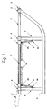
- the slide has two circular cylindrical, straight tubes as Longitudinal bars 1, which are rigidly interconnected by three cross struts 3 are connected. There is a seat between the two bars 1 7 attached. This can e.g. made of textile, plastic or Wood. It only extends between the rear two cross struts 3.
- struts 6 at their upper end with a ball or spherical joint 6b on the rear two cross struts 3 and with a detachable connection 6c, e.g. a snapping Detachable plug connection connected to the supports 4.
- a detachable connection 6c e.g. a snapping Detachable plug connection connected to the supports 4.
- connection 6c When connection 6c is released, struts 6 can be in position 6a be swung up. In this position you can e.g. by means of Snap elements to be held on the seat 7.
- the two Skids 5 with the supports 4 can now be on opposite sides the seat 7 can be folded. With that, the sled a small transport volume. He is in the use position stable and has good sliding properties.
- handles 8 can still be attached be indicated by dash-dotted lines in FIG. 1 and which make sledding easier.
- supports 4 and skid horns also rigidly connected to the longitudinal spars 1, but the Cross struts 3 with bearings 2 on the spars 1 can be pivoted.
Landscapes
- Engineering & Computer Science (AREA)
- Chemical & Material Sciences (AREA)
- Combustion & Propulsion (AREA)
- Transportation (AREA)
- Mechanical Engineering (AREA)
- Tents Or Canopies (AREA)
- Seats For Vehicles (AREA)
- Chain Conveyers (AREA)
- Materials For Medical Uses (AREA)
- Aerials With Secondary Devices (AREA)
- Motorcycle And Bicycle Frame (AREA)
- Walking Sticks, Umbrellas, And Fans (AREA)
- Handcart (AREA)
Description
- Figur 1
- eine Seitenansicht, und
- Figuren 2 und 3
- einen Querschnitt im aufgeklappten bzw. zusammengeklappten Zustand.
Claims (7)
- Klappbarer Schlitten mit zwei durch Querstreben (3) miteinander verbundenen Längsholmen (1), welche über Stützen (4) an zwei Kufen (5) abgestützt sind und eine Sitzfläche (7) tragen, wobei die Stützen (4) um die Längsachse der Längsholme (1) schwenkbar und mindestens in der ausgeschwenkten Lage der Kufen (5) arretierbar sind, wobei die Kufen (5) starr mit den Stützen (4) verbunden sind, und wobei die eine Kufe (5) auf die Oberseite, die andere auf die Unterseite der Sitzfläche (7) schwenkbar ist, dadurch gekennzeichnet, dass die Stützen (4) zur Arretierung durch Schrägstreben (6) mit zwei der Querstreben (3) lösbar verbunden sind.
- Schlitten nach Anspruch 1, wobei die Längsholme (1) kreiszylindrische Rohre sind.
- Schlitten nach Anspruch 1 oder 2, wobei die Schrägstreben (6) mit den Querstreben (3) gelenkig und mit den Stützen (4) lösbar verbunden sind.
- Schlitten nach einem der Ansprüche 1 bis 3, wobei die Kufenhörner ebenfalls um die Achse der Längsholme (1) schwenkbar gelagert sind.
- Schlitten nach einem der Ansprüche 1 bis 4, wobei die Längsholme (1) hinten frei abstehende Griffe (8) aufweisen.
- Schlitten nach einem der Ansprüche 1 bis 5, wobei die Querstreben (3) starr mit den Längsholmen (1) verbunden und die Stützen (4) auf den Längsholmen (1) schwenkbar gelagert sind.
- Schlitten nach einem der Ansprüche 1 bis 5, wobei die Stützen (4) starr und die Querstreben (3) schwenkbar mit den Längsholmen (1) verbunden sind.
Applications Claiming Priority (3)
| Application Number | Priority Date | Filing Date | Title |
|---|---|---|---|
| CH177796 | 1996-07-15 | ||
| CH177796 | 1996-07-15 | ||
| PCT/CH1997/000259 WO1998002341A1 (de) | 1996-07-15 | 1997-07-01 | Klappbarer schlitten |
Publications (2)
| Publication Number | Publication Date |
|---|---|
| EP0912385A1 EP0912385A1 (de) | 1999-05-06 |
| EP0912385B1 true EP0912385B1 (de) | 2000-03-29 |
Family
ID=4218376
Family Applications (1)
| Application Number | Title | Priority Date | Filing Date |
|---|---|---|---|
| EP97926954A Expired - Lifetime EP0912385B1 (de) | 1996-07-15 | 1997-07-01 | Klappbarer schlitten |
Country Status (5)
| Country | Link |
|---|---|
| EP (1) | EP0912385B1 (de) |
| AT (1) | ATE191190T1 (de) |
| AU (1) | AU3163497A (de) |
| DE (1) | DE59701372D1 (de) |
| WO (1) | WO1998002341A1 (de) |
Families Citing this family (2)
| Publication number | Priority date | Publication date | Assignee | Title |
|---|---|---|---|---|
| DE19834125A1 (de) * | 1997-12-23 | 1999-06-24 | Volkswagen Ag | Rodel |
| AT411242B (de) * | 2001-10-17 | 2003-11-25 | Mohr Dietmar | Schlitten mit zwei miteinander verbundenen längsholmen |
Family Cites Families (6)
| Publication number | Priority date | Publication date | Assignee | Title |
|---|---|---|---|---|
| FR1091190A (fr) * | 1954-01-07 | 1955-04-07 | Luge pliante à monture métallique | |
| FR1287557A (fr) * | 1961-02-03 | 1962-03-16 | Plianfer Ets | Perfectionnements apportés aux luges |
| FR80031E (fr) * | 1961-02-03 | 1963-03-01 | Plianfer Ets | Perfectionnements apportés aux luges |
| GB1004135A (en) | 1963-02-20 | 1965-09-08 | H J Gray & Sons Ltd | Sledges, toboggans and the like |
| CH424495A (de) | 1965-02-10 | 1966-11-15 | Sks Metallbau Ag | Klappschlitten |
| DE2359169A1 (de) * | 1973-11-28 | 1975-06-12 | Wilfried Kayser | Zusammenklappbarer schlitten |
-
1997
- 1997-07-01 AU AU31634/97A patent/AU3163497A/en not_active Abandoned
- 1997-07-01 DE DE59701372T patent/DE59701372D1/de not_active Expired - Fee Related
- 1997-07-01 EP EP97926954A patent/EP0912385B1/de not_active Expired - Lifetime
- 1997-07-01 WO PCT/CH1997/000259 patent/WO1998002341A1/de not_active Ceased
- 1997-07-01 AT AT97926954T patent/ATE191190T1/de active
Also Published As
| Publication number | Publication date |
|---|---|
| WO1998002341A1 (de) | 1998-01-22 |
| ATE191190T1 (de) | 2000-04-15 |
| DE59701372D1 (de) | 2000-05-04 |
| EP0912385A1 (de) | 1999-05-06 |
| AU3163497A (en) | 1998-02-09 |
Similar Documents
| Publication | Publication Date | Title |
|---|---|---|
| DE3528008C2 (de) | ||
| DE3876839T2 (de) | Stuhl- und wagenkombination. | |
| EP1366968B1 (de) | Zusammenklappbarer Schiebewagen für Kinder und/oder Puppen | |
| DE8614411U1 (de) | Rollstuhl | |
| EP2397388A2 (de) | Zusammenlegbarer Transportkarren | |
| DE202007011937U1 (de) | Vorderradeinheit für einen Kinderwagen | |
| DE20304921U1 (de) | Kinderkarre | |
| DE602004012693T2 (de) | Zusammenklappender Kinderwagen | |
| DE3007810A1 (de) | Zusammenklappbarer kinderwagen | |
| DE2535988C3 (de) | Zusammenklappbarer Kindersportkarren | |
| EP0345268B1 (de) | Zusammenklappbarer rodelschlitten | |
| DE19538080A1 (de) | Transportvorrichtung für leichte Boote, Surfboards und dgl. | |
| WO1998002341A1 (de) | Klappbarer schlitten | |
| DE202004018180U1 (de) | Einsatz für einen zusammenklappbaren Schiebewagen für Kinder und/oder Puppen | |
| DE202010013007U1 (de) | Schiebewagengestell | |
| WO1998056640A1 (de) | Skibob | |
| DE3116571A1 (de) | Schneegleitelement | |
| EP1390248A1 (de) | Fahrbare vorrichtung | |
| DE2941186A1 (de) | Wiegengestell | |
| DE8418222U1 (de) | Faltkinderwagen | |
| DE7527520U (de) | Standvorrichtung für Fahrräder als Heimsport-Gerät | |
| EP1707468B1 (de) | Klappschlitten | |
| DE2529297A1 (de) | Zusammenklappbarer kinderwagen | |
| EP1495938A2 (de) | Lenkbarer Rodelschlitten | |
| DE142681C (de) |
Legal Events
| Date | Code | Title | Description |
|---|---|---|---|
| PUAI | Public reference made under article 153(3) epc to a published international application that has entered the european phase |
Free format text: ORIGINAL CODE: 0009012 |
|
| 17P | Request for examination filed |
Effective date: 19990108 |
|
| AK | Designated contracting states |
Kind code of ref document: A1 Designated state(s): AT CH DE LI |
|
| GRAG | Despatch of communication of intention to grant |
Free format text: ORIGINAL CODE: EPIDOS AGRA |
|
| 17Q | First examination report despatched |
Effective date: 19990518 |
|
| GRAG | Despatch of communication of intention to grant |
Free format text: ORIGINAL CODE: EPIDOS AGRA |
|
| GRAH | Despatch of communication of intention to grant a patent |
Free format text: ORIGINAL CODE: EPIDOS IGRA |
|
| GRAH | Despatch of communication of intention to grant a patent |
Free format text: ORIGINAL CODE: EPIDOS IGRA |
|
| GRAA | (expected) grant |
Free format text: ORIGINAL CODE: 0009210 |
|
| AK | Designated contracting states |
Kind code of ref document: B1 Designated state(s): AT CH DE LI |
|
| REF | Corresponds to: |
Ref document number: 191190 Country of ref document: AT Date of ref document: 20000415 Kind code of ref document: T |
|
| REG | Reference to a national code |
Ref country code: CH Ref legal event code: EP |
|
| REF | Corresponds to: |
Ref document number: 59701372 Country of ref document: DE Date of ref document: 20000504 |
|
| REG | Reference to a national code |
Ref country code: CH Ref legal event code: NV Representative=s name: ISLER & PEDRAZZINI AG |
|
| PGFP | Annual fee paid to national office [announced via postgrant information from national office to epo] |
Ref country code: AT Payment date: 20000612 Year of fee payment: 4 |
|
| PGFP | Annual fee paid to national office [announced via postgrant information from national office to epo] |
Ref country code: DE Payment date: 20000629 Year of fee payment: 4 |
|
| EN | Fr: translation not filed | ||
| PLBE | No opposition filed within time limit |
Free format text: ORIGINAL CODE: 0009261 |
|
| STAA | Information on the status of an ep patent application or granted ep patent |
Free format text: STATUS: NO OPPOSITION FILED WITHIN TIME LIMIT |
|
| 26N | No opposition filed | ||
| PG25 | Lapsed in a contracting state [announced via postgrant information from national office to epo] |
Ref country code: AT Free format text: LAPSE BECAUSE OF NON-PAYMENT OF DUE FEES Effective date: 20010701 |
|
| PG25 | Lapsed in a contracting state [announced via postgrant information from national office to epo] |
Ref country code: LI Free format text: LAPSE BECAUSE OF NON-PAYMENT OF DUE FEES Effective date: 20010731 Ref country code: CH Free format text: LAPSE BECAUSE OF NON-PAYMENT OF DUE FEES Effective date: 20010731 |
|
| REG | Reference to a national code |
Ref country code: CH Ref legal event code: PL |
|
| PG25 | Lapsed in a contracting state [announced via postgrant information from national office to epo] |
Ref country code: DE Free format text: LAPSE BECAUSE OF NON-PAYMENT OF DUE FEES Effective date: 20020501 |