EP0911112A1 - Fluid pressure actuated combined centering and clamping device, in particular for use in the manufacture of motor vehicle bodies in the automotive industry - Google Patents
Fluid pressure actuated combined centering and clamping device, in particular for use in the manufacture of motor vehicle bodies in the automotive industry Download PDFInfo
- Publication number
- EP0911112A1 EP0911112A1 EP98118859A EP98118859A EP0911112A1 EP 0911112 A1 EP0911112 A1 EP 0911112A1 EP 98118859 A EP98118859 A EP 98118859A EP 98118859 A EP98118859 A EP 98118859A EP 0911112 A1 EP0911112 A1 EP 0911112A1
- Authority
- EP
- European Patent Office
- Prior art keywords
- centering
- tensioning
- cylinder
- clamping
- piston
- Prior art date
- Legal status (The legal status is an assumption and is not a legal conclusion. Google has not performed a legal analysis and makes no representation as to the accuracy of the status listed.)
- Withdrawn
Links
- 239000012530 fluid Substances 0.000 title claims description 3
- 238000004519 manufacturing process Methods 0.000 title 1
- 230000008878 coupling Effects 0.000 claims description 20
- 238000010168 coupling process Methods 0.000 claims description 20
- 238000005859 coupling reaction Methods 0.000 claims description 20
- 210000000078 claw Anatomy 0.000 claims description 6
- 238000007789 sealing Methods 0.000 claims description 6
- 238000010276 construction Methods 0.000 claims description 5
- 239000000463 material Substances 0.000 claims description 3
- 230000001154 acute effect Effects 0.000 claims description 2
- 238000000034 method Methods 0.000 claims description 2
- 230000015572 biosynthetic process Effects 0.000 claims 1
- 238000006073 displacement reaction Methods 0.000 claims 1
- 238000005755 formation reaction Methods 0.000 claims 1
- 239000002184 metal Substances 0.000 description 4
- 238000005553 drilling Methods 0.000 description 3
- 210000002435 tendon Anatomy 0.000 description 3
- 238000006243 chemical reaction Methods 0.000 description 2
- 238000010586 diagram Methods 0.000 description 1
- 238000005516 engineering process Methods 0.000 description 1
- 239000011159 matrix material Substances 0.000 description 1
- 230000000149 penetrating effect Effects 0.000 description 1
- 230000002040 relaxant effect Effects 0.000 description 1
- 238000003466 welding Methods 0.000 description 1
Images


Classifications
-
- B—PERFORMING OPERATIONS; TRANSPORTING
- B25—HAND TOOLS; PORTABLE POWER-DRIVEN TOOLS; MANIPULATORS
- B25B—TOOLS OR BENCH DEVICES NOT OTHERWISE PROVIDED FOR, FOR FASTENING, CONNECTING, DISENGAGING OR HOLDING
- B25B5/00—Clamps
- B25B5/06—Arrangements for positively actuating jaws
- B25B5/061—Arrangements for positively actuating jaws with fluid drive
-
- B—PERFORMING OPERATIONS; TRANSPORTING
- B23—MACHINE TOOLS; METAL-WORKING NOT OTHERWISE PROVIDED FOR
- B23K—SOLDERING OR UNSOLDERING; WELDING; CLADDING OR PLATING BY SOLDERING OR WELDING; CUTTING BY APPLYING HEAT LOCALLY, e.g. FLAME CUTTING; WORKING BY LASER BEAM
- B23K11/00—Resistance welding; Severing by resistance heating
- B23K11/36—Auxiliary equipment
-
- B—PERFORMING OPERATIONS; TRANSPORTING
- B23—MACHINE TOOLS; METAL-WORKING NOT OTHERWISE PROVIDED FOR
- B23K—SOLDERING OR UNSOLDERING; WELDING; CLADDING OR PLATING BY SOLDERING OR WELDING; CUTTING BY APPLYING HEAT LOCALLY, e.g. FLAME CUTTING; WORKING BY LASER BEAM
- B23K37/00—Auxiliary devices or processes, not specially adapted to a procedure covered by only one of the preceding main groups
- B23K37/04—Auxiliary devices or processes, not specially adapted to a procedure covered by only one of the preceding main groups for holding or positioning work
- B23K37/0426—Fixtures for other work
- B23K37/0435—Clamps
- B23K37/0443—Jigs
-
- B—PERFORMING OPERATIONS; TRANSPORTING
- B23—MACHINE TOOLS; METAL-WORKING NOT OTHERWISE PROVIDED FOR
- B23Q—DETAILS, COMPONENTS, OR ACCESSORIES FOR MACHINE TOOLS, e.g. ARRANGEMENTS FOR COPYING OR CONTROLLING; MACHINE TOOLS IN GENERAL CHARACTERISED BY THE CONSTRUCTION OF PARTICULAR DETAILS OR COMPONENTS; COMBINATIONS OR ASSOCIATIONS OF METAL-WORKING MACHINES, NOT DIRECTED TO A PARTICULAR RESULT
- B23Q3/00—Devices holding, supporting, or positioning work or tools, of a kind normally removable from the machine
- B23Q3/18—Devices holding, supporting, or positioning work or tools, of a kind normally removable from the machine for positioning only
- B23Q3/183—Centering devices
-
- B—PERFORMING OPERATIONS; TRANSPORTING
- B25—HAND TOOLS; PORTABLE POWER-DRIVEN TOOLS; MANIPULATORS
- B25B—TOOLS OR BENCH DEVICES NOT OTHERWISE PROVIDED FOR, FOR FASTENING, CONNECTING, DISENGAGING OR HOLDING
- B25B5/00—Clamps
- B25B5/06—Arrangements for positively actuating jaws
- B25B5/12—Arrangements for positively actuating jaws using toggle links
- B25B5/122—Arrangements for positively actuating jaws using toggle links with fluid drive
-
- B—PERFORMING OPERATIONS; TRANSPORTING
- B23—MACHINE TOOLS; METAL-WORKING NOT OTHERWISE PROVIDED FOR
- B23K—SOLDERING OR UNSOLDERING; WELDING; CLADDING OR PLATING BY SOLDERING OR WELDING; CUTTING BY APPLYING HEAT LOCALLY, e.g. FLAME CUTTING; WORKING BY LASER BEAM
- B23K2101/00—Articles made by soldering, welding or cutting
- B23K2101/18—Sheet panels
Abstract
Description
Die Erfindung betrifft eine druckmittelbetätigbare kombinierte Zentrier- und Spannvorrichtung.The invention relates to a combined centering and actuatable by pressure medium Jig.
Vielfach müssen Blechteile an Karosseriegruppen angeschweißt werden. Hierzu ist es wünschenswert, daß zum Beispiel Kniehebelspannvorrichtungen durch Öffnungen von Karosserieteilen hindurchgreifen und die miteinander durch Punktschweißen oder dergleichen zu verbindenden Teile festspannen und bis zu ihrer Fixierung auch in der vorbestimmten Lage zentrieren.Sheet metal parts often have to be welded to body groups. To this end, it is desirable that, for example, toggle clamps reach through openings of body parts and with each other clamp parts to be connected by spot welding or the like and center it in the predetermined position until it is fixed.
Durch die DE 39 36 396 C1 ist eine druckmittelbetätigbare Kniehebelspannvorrichtung,
insbesondere für Karosserieteile, vorbekannt, bestehend aus
wobei
in which
Diese Spannvorrichtung ist als Unterbauspanner ausgebildet, deren Spannglied am spannseitigen Ende einen Spannhaken aufweist, der durch eine Öffnung der Werkstückauflagefläche hindurchgreift und mit seiner Aufspannfläche der Spannvorrichtung zugewandt ist. Ein am Gehäuse befestigter, einen Hohlraum bildender Zentrierdorn ist vorgesehen, der den Spannhaken in der entspannten Stellung umschließt und in der Spannstellung radial heraustreten läßt.This clamping device is designed as a base clamp, the tendon has a tension hook at the tension-side end, which passes through an opening reaches through the workpiece support surface and with its clamping surface faces the tensioning device. A cavity attached to the case Forming centering mandrel is provided which the clamping hook in the encloses relaxed position and step out radially in the clamping position leaves.
Durch die DE 39 38 208 ist eine weitere druckmittelbetätigbare Kniehebelspannvorrichtung,
insbesondere für Karosserieteile, vorbekannt, bestehend aus
wobei
in which
Einem Schwenkbolzen ist mindestens eine Rolle zugeordnet, mit der der Schwenkbolzen in einem Kulissenschlitz geführt ist, wobei der Kulissenschlitz unter einem spitzen Winkel die Längsachse der Kolbenstange schneidet. Eine Lasche der Kniehebelgelenkanordnung ist über eine parallel zum Kolbenstangenbolzen verlaufende ortsunbewegliche Kniehebelgelenkachse mit einer Schwinge um eine gehäusefeste Achse schwenkbeweglich verbunden, deren Schwenklängsachse parallel zum Kolbenstangenbolzen und zur Kniehebelgelenkachse verläuft. A pivot pin is assigned at least one role with which the Swivel pin is guided in a slot slot, the slot slot intersects the longitudinal axis of the piston rod at an acute angle. A Tab of the toggle joint arrangement is parallel to the piston rod pin running stationary toggle joint axis with a Swing arm pivotally connected about a housing-fixed axis, the Longitudinal swivel axis parallel to the piston rod pin and the toggle joint axis runs.
Der Erfindung liegt die Aufgabe zugrunde, eine druckmittelbetätigbare kombinierte Zentrier- und Spannvorrichtung, insbesondere zur Verwendung im Karosseriebau der Kfz-Industrie, zu schaffen, mit der solche Bauteile, zum Beispiel Bleche aus dem Karosseriebau, nicht nur zuverlässig gegeneinander zentriert, sondern auch mit der erforderlichen hohen Anpreßkraft auf möglichst großer Fläche, die sich um den Zentrierbolzen verteilt, gehalten werden können.The invention has for its object a combined pressure-actuated Centering and clamping device, in particular for use in body construction the automotive industry, with which to create such components, for example Sheets from the body shop, not only reliably against each other centered, but also with the required high contact pressure on as possible large area that is distributed around the centering pin can be kept.
Die Aufgabe wird durch die in Patentanspruch 1 wiedergegebenen Merkmale
gelöst.The object is achieved by the features set out in
Bei der Erfindung ist das Spannteil unmittelbar in und an dem Zentrierteil angeordnet. Dadurch ergibt sich eine raumsparende Konstruktion. In the invention, the clamping part is arranged directly in and on the centering part. This results in a space-saving construction.
Ein weiterer Vorteil besteht darin, daß durch die Anordnung des Spannteils in und an dem Zentrierteil nur durch eine Hubbewegung des Zentrierteils in die dafür vorgesehenen Öffnungen der zu zentrierenden Bleche das Spannteil aus dem Zentrierteil ausgefahren werden kann.Another advantage is that the arrangement of the clamping part in and on the centering part only by a lifting movement of the centering part in the provided openings of the sheets to be centered from the clamping part the centering part can be extended.
Ein besonderer Vorteil besteht indessen darin, daß durch die besondere Ausbildung der erfindungsgemäßen druckmittelbetätigten kombinierten Zentrier- und Spannvorrichtung man es in der Hand hat, nicht nur - wie beim Stand der Technik - einseitig, sondern mehrseitig zu spannen, da die erfindungsgemäße Lösung es ermöglicht, das Spannteil mehrteilig auszubilden, um es gleichsinnig und synchron beim Spannen aus dem Zentrierteil heraustreten zu lassen, so daß die zu zentrierenden und zu spannenden Bauteile über den Umfang des Zentrierteils großflächig gespannt werden können. Dadurch ergibt sich nicht nur eine günstige Krafteinleitung, sondern eine großflächige, zuverlässige Zentrierung um das Zentrierteil herum, so daß die Bauteile mit hoher Präzision arretiert werden können. Dies ist von besonderem Vorteil im Karosseriebau der Kfz-Industrie. A particular advantage, however, is that the special training the pressure-operated combined centering and Clamping device you have in your hand, not only - as with the state of the Technology - one-sided, but to span more than one, since the invention Solution makes it possible to design the clamping part in several parts in order to make it the same direction and let it come out of the centering part synchronously when tensioning that the components to be centered and exciting over the circumference of the Centering part can be stretched over a large area. This doesn't just result a cheap introduction of force, but a large, reliable centering around the centering part so that the components are locked with high precision can be. This is particularly advantageous in the body shop of the automotive industry.
Zentrier- und Spannteil werden außerdem sowohl beim Spannen wie auch beim Lösen druckmittelangetrieben, zum Beispiel durch Druckluft. Im Bedarfsfalle kann jedoch auch ein hydraulisches Medium zum Einsatz kommen, obwohl insbesondere im Karosseriebau der Kfz-Industrie bevorzugt Druckluft zur Anwendung kommt, die auch für die in der Regel eingesetzten Kniehebelspannvorrichtungen im Betrieb zur Verfügung steht.Centering and clamping part are also both when clamping and when releasing pressure medium driven, for example by compressed air. If necessary however, a hydraulic medium can also be used, though Especially in the body shop of the automotive industry, compressed air is preferred Application comes also for the toggle clamps usually used is available in the company.
In Patentanspruch 2 ist eine vorteilhafte Ausführungsform beschrieben, bei
welcher dem bolzenförmigen Zentrierteil und dem Spannteil je ein druckmittelangetriebener
Zylinder zugeordnet sind, wobei die beiden Zylinder koaxial
hintereinander angeordnet werden können. Dadurch ergibt sich eine besonders
kompakte Bauform.In
Vorteilhafterweise sind der Bewegungszylinder und der Spannzylinder einstückig miteinander verbunden. Dadurch ergeben sich wenig lose Teile. Außerdem trägt diese Bauweise zu einer weiteren Verkleinerung der äußeren Bauabmessungen bei (Patentanspruch 3). The movement cylinder and the clamping cylinder are advantageously connected to one another in one piece. This results in little loose parts. In addition, this design contributes to a further reduction in the outer dimensions ( claim 3 ).
Eine besonders vorteilhafte Ausführungsform ist in Patentanspruch 4 beschrieben.
Hierbei kann das Spannteil zwei Doppelhebel aufweisen, die auf
diametral gegenüberliegenden Seiten des Zentrierteiles auf die zu spannenden
und zu haltenden flächigen Bauteile einwirken können.A particularly advantageous embodiment is described in
Eine besonders vorteilhafte Ausführungsform ist in Patentanspruch 5 beschrieben.
Bei dieser Ausführungsform besteht das Spannteil aus zwei hakenförmigen
Doppelhebeln, die auf einer gemeinsamen zentrischen Achse im und
am Zentrierteil gelagert sind. Diese hakenförmigen Spannhebel treten beim
Spannvorgang aus der Kontur des bolzenförmigen, am freien Ende in der Regel
abgerundeten oder verjüngten Spannteils, heraus, können aber beim Entspannen
auch wiederum in die Kontur, vornehmlich eine längliche Ausnehmung
im Spannteil, einschwenken, woraufhin sich dann die Spann- und Zentriervorrichtung
wieder einfahren läßt, damit die zu spannenden und zu zentrierenden
Bauteile entfernt werden können. Vorteilhafterweise sind die hakenförmigen
Doppelhebel scherenförmig durch Schwenkachsen miteinander verbunden und
sind durch weitere Schwenkachsen über Hebel mit einer zentrischen
Kupplungsachse gekuppelt, die mit einer Kolbenstange verbunden ist. Die Kolbenstange
wird durch einen Spannzylinder angetrieben, der abwechselnd beidseitig
durch Druckmitteldruck zu beaufschlagen ist. A particularly advantageous embodiment is described in
In Patentanspruch 6 ist eine weitere vorteilhafte Ausführungsform beschrieben.A further advantageous embodiment is described in
Auch Patentanspruch 7 beschreibt eine konstruktiv einfache Konstruktion.
In Patentanspruch 8 ist eine Vorrichtung beschrieben, bei der der Spannkolben den Kolbenkörper des Bewegungszylinders über eine Schleppkupplung in Öffnungsstellung mitnimmt.In claim 8 a device is described in which the tensioning piston takes the piston body of the movement cylinder with it via a drag clutch in the open position.
Dies geschieht gemäß Patentanspruch 9 allerdings erst dann, wenn der Spannkolben die Spannvorrichtung vollständig in die Kontur des Zentrierteils zurückbewegt hat. Solange wird durch Anstehen von Druckmitteldruck im Bewegungszylinder dieser verriegelt gehalten. Wenn die Spannvorrichtung vollständig in die Kontur des Zentrierteils eingefahren ist, wird die Schleppverbindung zwischen Spannkolben und Kolbenkörper hergestellt, so daß das Zentrierteil über den Spannzylinder in seine Lösestellung gefahren wird, wobei sich die vollkommen in die äußere Kontur des bolzenförmigen Spannteils hineinbewegten Spannhebel zusammen mit dem Zentrierteil in den Bewegungszylinder zurückbewegt werden. Dieser Bewegungsablauf kann durch eine Folgesteuerung gesteuert werden.This happens according to claim 9, however, only when the clamping piston has moved the clamping device completely back into the contour of the centering part. As long as pressure fluid pressure is present in the motion cylinder, it is kept locked. When the clamping device is completely retracted into the contour of the centering part, the towing connection between the clamping piston and the piston body is established, so that the centering part is moved into its release position via the clamping cylinder, the clamping lever moving completely into the outer contour of the bolt-shaped clamping part together with the Centering part can be moved back into the movement cylinder. This sequence of movements can be controlled by a sequence control.
Patentanspruch 10 beschreibt eine konstruktiv vorteilhafte Ausführungsform
der Erfindung.
Bei einer besonders vorteilhaften Ausführungsform der Erfindung ist das bolzenförmige Zentrierteil auf dem übrigen Teil seiner Länge von einem Langloch durchsetzt, das zum Inneren, den Bewegungszylinder zugekehrten Endabschnitt in diesen offen ausmündet und an dazu 90 Grad versetzten Seiten ebenfalls. Auf diese Weise lassen sich die Hebel des Spannteils in dem Langloch anordnen (Patentanspruch 11).In a particularly advantageous embodiment of the invention, the bolt-shaped centering part is penetrated over the remaining part of its length by an elongated hole which opens out towards the interior, the end section facing the movement cylinder, and likewise on sides offset from it at 90 degrees. In this way, the levers of the clamping part can be arranged in the elongated hole ( claim 11 ).
Bevorzugt sind die Spannhebel gemäß Patentanspruch 12 als flache, aufeinanderliegende Bauteile ausgebildet. Dadurch braucht einerseits das bolzenförmige Teil nicht so sehr durch das Langloch geschwächt zu werden, andererseits wird indessen ermöglicht, das auch bei relativ flachen Hebeln diese durch Ausschwenken auf gegenüberliegenden Seiten mit großer Kraft auf die zu haltenden Bauteile ausgefahren werden können, da die Beanspruchung nicht orthogonal zu ihrer Oberfläche, sondern in Richtung des großen Widerstands- und Trägheitsmomentes der Spannhebel auf diese einwirken, so daß große Kräfte übertragbar sind.The clamping levers are preferably formed as a flat, superposed elements according to claim 12th On the one hand, this means that the bolt-shaped part does not have to be weakened so much through the elongated hole, on the other hand, it makes it possible that even with relatively flat levers, they can be extended with great force onto the components to be held by swiveling out on opposite sides, since the stress is not orthogonal act on their surface, but in the direction of the large moment of resistance and moment of inertia of the tensioning lever, so that large forces can be transmitted.
In Patentanspruch 13 ist eine weitere vorteilhafte Ausführungsform beschrieben,
was auch für Patentanspruch 14 gilt.
Wird eine Ausführungsform nach Patentanspruch 15 gewählt, so läßt sich das
Zentrierteil materialmäßig einstückig mit dem Kolbenkörper verbinden, was zur
Verringerung von Einzelteilen beiträgt.If an embodiment is selected according to
Eine kompakte Ausführungsform ist in Patentanspruch 16 beschrieben.A compact embodiment is described in
Besonders ist es, wenn eine Ausführungsform nach Patentanspruch 17 gewählt
wird. Bei dieser ist die Kupplungsachse verdrehsicher in Längsschlitzen
geführt, während andererseits Schwenkachsen und auch die Enden von
Heben in Erweiterungen des Bewegungszylinders eintreten können. Hierfür beschreibt
Patentanspruch 18 eine besonders vorteilhafte Ausführungsform. It is special if an embodiment is selected according to
In Patentanspruch 19 ist eine Ausführungsform beschrieben, die mit nur
einem Spannhaken arbeitet. Die Reaktionskräfte werden durch die Rollenführung
in dem Gehäuse aufgenommen.In
In der Zeichnung ist die Erfindung - teils schematisch - beispielsweise veranschaulicht. Es zeigen:
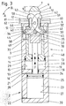
- Fig. 1
- eine erfindungsgemäße druckmittelbetätigbare, kombinierte Zentrier- und Spannvorrichtung im Axiallängsschnitt, teils in der Ansicht, in gelöster Stellung, also in Null-Lage der Zentrier- und Spannvorrichtung;
- Fig. 2
- die aus Fig. 1 ersichtliche Vorrichtung nach dem Ausfahren des Zentrierteils;
- Fig. 3
- die aus den Fig. 1 und 2 ersichtliche Vorrichtung nach dem Ausfahren des Spannteils, in einem Längsschnitt nach der Linie III - III der Fig. 2;
- Fig. 4
- die aus den Fig. 1
bis 3 ersichtliche Vorrichtung beim Einfahren der Spann- und Zentriervorrichtung, teils als Schaltplan und - Fig. 5
- einen um 90 Grad versetzt zu Fig. 1 durch die Vorrichtung geführten Axiallängsschnitt;
- Fig. 6
- eine weitere Ausführungsform der Erfindung, gleichfalls im Längsschnitt, teils abgebrochen dargestellt.
- Fig. 1
- a combined centering and tensioning device actuated by pressure medium according to the invention in axial longitudinal section, partly in view, in the released position, ie in the zero position of the centering and tensioning device;
- Fig. 2
- the device shown in Figure 1 after extending the centering part.
- Fig. 3
- the device shown in Figures 1 and 2 after extending the clamping part, in a longitudinal section along the line III - III of Fig. 2.
- Fig. 4
- the device shown in FIGS. 1 to 3 when retracting the clamping and centering device, partly as a circuit diagram and
- Fig. 5
- an axial longitudinal section offset by 90 degrees to FIG. 1 through the device;
- Fig. 6
- another embodiment of the invention, also shown in longitudinal section, partly broken.
In der Zeichnung ist die druckmittelbetätigbare kombinierte Zentrier- und Spannvorrichtung an einer Ausführungsform veranschaulicht, wie sie mit besonderem Vorteil im Karosseriebau der Kfz-Industrie zum Einsatz kommt.In the drawing, the combined centering and pressure medium operated Clamping device illustrated on one embodiment, as with particular Advantage in body construction of the automotive industry is used.
Die erfindungsgemäße Vorrichtung besteht im wesentlichen aus zwei koaxial
und damit hintereinander angeordneten Zylindereinheiten, von denen die eine
als Bewegungszylinder 1 und die andere als Spannzylinder 2 ausgebildet ist.
Vorliegend sind die beiden Zylinder 1, 2 einstückig ausgebildet, sie können
aber auch aus trennbaren und nur funktionell miteinander, z. B. durch Schrauben
verbindbare und demgemäß voneinander lösbare Zylinder bestehen. The device according to the invention essentially consists of two coaxial
and thus cylinder units arranged one behind the other, one of which
is designed as a
Der Bewegungszylinder 1 setzt sich aus einem äußeren Zylinder 3 mit stirnseitigem
Zylinderdeckel 4 zusammen, der durch mehrere Schrauben gehalten ist.
Die Schrauben sind in mit Gewinde versehene Sackbohrungen des Zylinders 3
eingeschraubt und über den Umfang des Zylinders 3 gleichmäßig verteilt angeordnet.
Im übrigen sind die Schrauben in vertieften Senkbohrungen des
Zylinderdeckels 4 angeordnet, so daß die Schraubenköpfe versenkt
angeordnet sind.The
Der Zylinderdeckel 4 besitzt eine zentrische Öffnung 5 zum Durchtritt eines bolzenförmigen
Zentrierteils 6, das an seinem freien Endabschnitt an seiner äußeren
Mantelfläche 7 abgerundet oder konisch verlaufend ausgebildet ist, um es
besser in nicht dargestellte Ausnehmungen von flächigen Bauteilen, zum Beispiel
Blechen von Karosserien hineinbewegen zu können. Auf seinem sich an
dem konischen oder abgerundet verlaufenden Endabschnitt anschließenden
Längenabschnitt 8 ist das Zentrierteil 6 im wesentlichen als Hohlbolzen ausgebildet,
besitzt also ein sich an den stirnseitigen Längenabschnitt 9 im Innern
des bolzenförmigen Zentrierteils 6 erstreckendes schlitzförmiges Langloch 10,
das das Zentrierteil 6 quer und auf seiner gesamten Restlänge nach unten
durchsetzt. The
Wie man aus Fig. 5 erkennt, ist das Zentrierteil 6 über einen einstückigen
Flansch 11 mit einem zylindrischen Kolbenkörper 12 verbunden, der am Ende
einstückig mit einem Bewegungskolben 13 verbunden ist, der über eine Dichtung
14 längsverschieblich und dichtend an der Zylinderinnenwand 15 des
äußeren Zylinders 3 geführt ist. Der Flansch 11 bildet einen Teil des Kolbenkörpers
12.As can be seen from Fig. 5, the centering
An dem dem Zylinderdeckel 4 entgegengesetzten Endabschnitt ist der Bewegungszylinder
1 durch einen Enddeckel 16 verschlossen, der vorliegend einstückig
ausgebildet, aber auch als getrenntes Bauteil durch Dichtungen
druckmitteldicht in dem Bewegungszylinder 1 abgedichtet sein kann. Der Enddeckel
16 ist dann mit einer Ringschulter an der Stirnseite des Zylinders 3 abgestützt
und greift mit seinem übrigen Längenabschnitt in einen Zylinderraum
19 hinein und ist in diesem Bereich durch die Dichtung druckmitteldicht abgedichtet,
während eine andere Dichtung sich gegen die Stirnseite des Zylinders
3 druckmitteldicht anlegt. At the end section opposite the
Außerdem kann der Enddeckel 16 durch einen Ringflansch des Spannzylinders
2 mittels einer eingedrehten Ringschulter gehalten werden, so daß der Enddeckel
16 achsial und radial formschlüssig arretiert ist. Die Dichtung ist in einer
Ringnut des Ringflansches angeordnet.In addition, the
An dem dem Enddeckel 16 entgegengesetzten Endabschnitt des Spannzylinders
2 ist ein Enddeckel 20 druckmitteldicht angeordnet. Dieser Enddeckel 20
kann auch als lösbares, durch Schrauben gehaltenes Bauteil mit dem Zylinderkörper
des Spannzylinders 2 verbunden sein.At the end section of the clamping cylinder opposite the
Bei 21 und 22 münden Anschlußkanäle zum Zuführen von Druckmittel endseitig
in Zylinderräume 23 bzw. 24 ein, die durch einen Spannkolben 25 mit wechselnder
Größe begrenzt werden, der durch mindestens ein Dichtungselement
26 längsverschieblich und dichtend an der Zylinderinnenwand 27 des Spannzylinders
2 geführt ist.At 21 and 22, connection channels for supplying pressure medium open out at the end
in
Der Spannkolben 25 weist z. B. eine zentrische mit Gewinde versehene Bohrung
auf, in der ein mit Gewinde versehener Endabschnitt einer Kolbenstange
28 befestigt ist, die über eine Dichtung 29 abgedichtet den Enddeckel 16 längsverschieblich
durchgreift. Der Enddeckel 16 kann auch als getrenntes Bauteil
mit dem Zylinder 3 des Bewegungszylinders 1 ausgeführt und mit diesem durch
Schrauben, Einklemmen oder dergleichen verbunden sein. Mit 18 ist eine
Dichtung bezeichnet.The
Die Kolbenstange 28 ist an ihrem anderen Ende mit einer Kupplung 30, beispielsweise
durch Gewinde oder dergleichen, gekuppelt. Diese Kupplung 30 ist
als Lagergabel mit materialmäßig einstückigen Lagerflanschen 31 und 32
versehen, die in dem aus Fig. 5 ersichtlichen Längsschnitt zusammen mit dem
sie verbindenden Steg eine U-förmige Form bilden. Die Lagerflansche 31 und
32 weisen koaxial zueinander angeordnete Bohrungen auf, durch die eine
Kupplungsachse 33 hindurchgreift, auf deren mittleren Längenabschnitt zwei
laschenförmige Hebel 34 und 35 schwenkbeweglich sowie parallel zueinander
verschwenkbar angeordnet sind. Zu diesem Zweck weisen die laschenförmigen
Hebel 34 und 35 sie jeweils durchdringende Durchgangsbohrungen auf, durch
die die Kupplungsachse 33 hindurchgreift. Die Kupplungsachse 33 ist im
übrigen an ihren Endabschnitten über Hülsen 36, 37, die sich mit ihren Stirnseiten
an je einer der Lagerflansche 31 bzw. 32 abstützen, durch geeignete Arretierungen,
zum Beispiel durch Seegerringe, axial unverschieblich arretiert. The
Die Enden jedes laschenförmigen Hebels 34, 35 weisen je eine Bohrung 38
bzw. 39 auf, deren Mittelpunkt jeweils auf einer Mittellinie 40 bzw. 41 angeordnet
ist, die ebenfalls geradlinig durch den Mittelpunkt der Kupplungsachse 33
hindurchläuft. Jede der Bohrungen 38 bzw. 39 ist koaxial zu einer weiteren
Bohrung (nicht besonders bezeichnet) angeordnet, die am unteren Endbereich
(in der Zeichnungsebene gesehen) von je einem Spannhaken 42 bzw. 43 angeordnet
ist. Durch die Bohrung 38 bzw. 39 und die jeweils damit korrespondierende
Bohrung des betreffenden Spannhakens 42 bzw. 43 greift jeweils eine
Schwenkachse 44 bzw. 45. Die Schwenkachsen 44 bzw. 45 verlaufen mit ihren
Längsachsen parallel zur Längsachse der Kupplungsachse 33, so daß auch die
Spannhaken 42 und 43 parallel zur Ebene wie die laschenförmigen Hebel 34
bzw. 35, also in Richtung A bzw. B, schwenken.The ends of each tab-shaped
Die Spannhaken 42 und 43 bilden das Spannteil der Vorrichtung.The clamping hooks 42 and 43 form the clamping part of the device.
Etwa im mittleren Längenbereich der Spannhaken 42 bzw. 43 sind die als Doppelhebel
ausgebildeten Spannhaken 42 und 43 durch eine Lagerachse 46
schwenkbeweglich miteinander gekuppelt, die in einer Bohrung 47 des Zentrierteils
6, und zwar in den Wandungen des hülsenförmigen Abschnittes des
Zentrierteils 6, gelagert ist (Fig. 5). Die Längsachse der Lagerachse 46 verläuft
ebenfalls parallel zur Kupplungsachse 33 und damit auch parallel zu den
Längsachsen der Schwenkachsen 44 und 45.Approximately in the middle length range of the tensioning hooks 42 and 43 are double levers
trained
In die zentrische Öffnung 5 des stirnseitigen Zylinderdeckels 4 kann ein
Flansch mit einem Ringkragen eingreifen, der vor den Mündungsöffnungen der
Bohrung 47 angeordnet ist. Der Flansch wird durch mehrere über seinen
Umfang verteilte Schrauben gehalten.In the
Der Kolbenkörper 12 des Bewegungszylinders 1 kann an seinem dem Spannhaken
42, 43 abgekehrten Endabschnitt durch einen Deckel verschlossen
ausgebildet sein, der als separates Teil in den Kolbenkörper 12 stirnseitig eingeschraubt
und durch eine Dichtung abgedichtet ist, während er bei der Ausführungsform
aus der Zeichnung materialmäßig einstückig mit dem Kolbenkörper
12 ausgebildet ist.The
Der Deckel kann von der Kolbenstange 28 durch eine Dichtung druckmitteldicht
durchgriffen sein. Bei einer Ausführungsform kann die Kupplung 30 über
Gewinde mit der Kolbenstange 28 verbunden sein, während sie bei der Ausführungsform
nach der Zeichnung einstückig mit der Kolbenstange 28 ausgebildet
ist. The cover can be pressure-tight from the
Bei 48 ist eine ringförmige Anschlagschulter im Zylinder 3 angeordnet. Die Anschlagschulter
48 kann aber auch an einer Anschlaghülse angeordnet sein, die
an der Innenwand des äußeren Zylinders 3 befestigt ist.At 48, an annular stop shoulder is arranged in the
Deutlich erkennt man aus den Fig. 1 bis 3, daß der Kolbenkörper 12 an seinem
den Spannhaken 42, 43 zugekehrten Endabschnitt auf diametral gegenüberliegenden
Seiten mit Aussparungen 49 bzw. 50 versehen ist, durch die sowohl
endseitige Abschnitte der Spannhaken 42 und 43, als auch die Schwenkachsen
44 und 45 zusammen mit Endabschnitten der laschenförmigen Hebel 34
und 35 in je eine Erweiterung 51 bzw. 52 des Bewegungszylinders 1 hineinzutreten
vermögen (Spannstellung gemäß Fig. 3).1 to 3 that the
Wie man aus Fig. 5 erkennt, sind die Enden der Kupplungsachse 33 mit den
Hülsen 36 und 37, die als Rollen ausgebildet sein können, in korrespondierenden
Längsschlitzen 53, 54 des Kolbenkörpers 12 und des ihn umgebenden äußeren
Zylinders 3 in Längsachsrichtung verdrehsicher geführt.5, the ends of the
Mit 55 ist ein ggf. mit Gewinde versehener Anschlußkanal bezeichnet. With 55 a possibly provided connection channel is designated.
Die Bezugszeichen 56 und 57 bezeichnen Druckmittelleitungen, die über eine Steuereinheit, zum Beispiel Mehrwegeventile, an eine Druckmittelzufuhrleitung angeschlossen sind, die durch eine motorisch angetriebene Pumpe oder dergleichen mit Druckmitteldruck (hydraulisch oder pneumatisch) zu versorgen ist.The reference numerals 56 and 57 denote pressure medium lines, which have a Control unit, for example multi-way valves, to a pressure medium supply line are connected by a motor-driven pump or to supply the same with pressure medium pressure (hydraulic or pneumatic) is.
Deutlich ist aus Fig. 3 zu erkennen, daß die beiden Spannhaken 42 und 43 an
ihren einander zugekehrten Seitenwänden nach einem Kreisbogen verlaufend
ausgebildet sind, während ihre voneinander abgekehrten Rücken nach mehreren
Kreisbögen und Kurven abgerundet ausgebildet sind. Spannköpfe 58 bzw.
59 sind hakenförmig mit nach unten gerichteten Spannklauen 17 bzw. 60 versehen,
die unmittelbar auf die flächigen Bauteile 61 bzw. 62 einwirken und
diese auf der Oberseite einer Auflagematrize fest einspannen und halten.It can be clearly seen from FIG. 3 that the two tensioning hooks 42 and 43 are on
their side walls facing each other in a circular arc
are trained while their backs turned away after several
Arcs and curves are rounded. Clamping heads 58 or
59 are hook-shaped with downward-facing
Wie man erkennt, treten hierbei die Spannhaken 42 und 43 mit ihren
Spannklauen 17 und 60 aus dem Zentrierteil 6 hervor.As can be seen, the clamping hooks 42 and 43 come with their
Clamping
Außerdem ist zu erkennen, daß der Bewegungszylinder 1 und der Spannzylinder
2 baulich, körperlich einstückig und koaxial zueinander angeordnet sind, so
daß sich eine sehr kompakte Bauform ergibt. It can also be seen that the
Die Wirkungsweise der aus der Zeichnung ersichtlichen Ausführungsform ist folgende:The mode of operation of the embodiment shown in the drawing is the following:
In der Ausgangsstellung gemäß Fig. 1 wird über die betreffende Steuereinheit,
die Leitung 56 und der Anschlußkanal 55 der Zylinderraum 19 mit Druckmittel,
z. B. Druckluft, beaufschlagt, so daß sich der Kolbenkörper 12 des Bewegungszylinders
2 in Richtung X bewegt. Da das Zentrierteil 6 einstückig mit
dem Kolbenkörper 12 verbunden ist, wird es ebenfalls in Richtung X bewegt,
also aus der Vorrichtung herausgefahren (Fig. 2) und zentriert dadurch die auf
der Vorrichtung angeordneten flächigen Bauteile, zum Beispiel Karosseriebleche
61, 62.In the starting position according to FIG. 1, the control unit in question,
the
Der Spannzylinder 2 ist hierbei noch nicht betätigt.The
Nach Erreichen der Stellung gemäß Fig. 2 wird über die Steuereinheit und die
Leitung 63 und den Anschlußkanal 22 der Zylinderraum 23 des Spannzylinders
2 mit Druckmittel beaufschlagt, so daß sich der Spannkolben 25 und mit ihm
die Kolbenstange 28 in Richtung X bewegen und über die Kupplung 30
auch die laschenförmigen Hebel 34 und 35 über die Kupplungsachse 33 mitnehmen.
Dabei schwenken die laschenförmigen Hebel 34 und 35 um die
Kupplungsachse 33 auseinander. Gleichzeitig schwenken die doppelhebelförmigen
Spannhaken 42 und 43 aus der Stellung gemäß Fig. 2 allmählich in die
Stellung gemäß Fig. 3, also in Spannstellung. Hierbei treten sie aus der äußeren
Umgrenzung des bolzenförmigen Zentrierteils 6 in die aus Fig. 3 ersichtliche
Lage heraus und spannen die durch das Zentrierteil 6 zentrierten flächigen
Bauteile 61, 62 auf diametral einander gegenüberliegenden Seiten, eng an dem
Zentrierteil 6 fest gegen die Oberseite des Zylinderdeckels 4 oder eines hier
angeordneten Flansches ein. In dieser Position werden sie solange gehalten,
solange die Druckmittelbeaufschlagung auf die Unterseite des Spannkolbens
25 erfolgt.After reaching the position shown in FIG. 2, the control unit and the
Das Einfahren geschieht durch Beaufschlagung der Ringseite des Spannzylinders,
also über die Steuereinheit, die Leitung 57 und den Anschlußkanal 21
sowie den Zylinderraum 24. Dadurch bewegt sich der Spannkolben 25 in Richtung
Y und nimmt über Kupplung 30, die Kupplungsachse 33 auch die laschenförmigen
Hebel 34 und 35 mit. Die Spannhaken 42 und 43 werden dabei über
ihre Schwenkachse 44 und 45 wieder in ihre aus Fig. 1 und 2 ersichtliche Lage
bis in das Langloch 10 des Zentrierteils 6 eingeschwenkt. Der Kolbenkörper 12
des Bewegungszylinders 1 wird währenddessen durch Beaufschlagung mittels
Druckmittel über den Anschlußkanal 55 gehalten. Während des Einfahrens der
Spannhaken 42 und 43 muß nämlich der Kolbenkörper 12 des Bewegungszylinders
2 zunächst in seiner Zentrierstellung verbleiben.The retraction takes place by acting on the ring side of the clamping cylinder,
that is, via the control unit, the
Nachdem der Spannkolben 25 des Spannzylinders 2 durch Bewegung in
Richtung Y wieder in seine Null-Lage oder annähernd in seine Null-Lage bewegt
wurde, wird die Zylinderseite des Kolbenkörpers 12 für das Zentrierteil 6
druckentlastet und der Kolbenkörper 12 des Bewegungszylinders 2 wird über
eine Art Schleppverbindung mittels der Kupplung 30 in Richtung Y bis in seine
Ausgangsposition gemäß Fig. 1 durch den Spannkolben 25 bewegt.After the
In Fig. 6 ist eine weitere Ausführungsform der Erfindung veranschaulicht, bei der für Teile gleicher Funktion die gleichen Bezugszeichen wie bei den vorbeschriebenen Ausführungsformen verwendet wurden.A further embodiment of the invention is illustrated in FIG the same reference numerals for parts with the same function as for the above-described embodiments were used.
Die Ausführungsform nach Fig. 6 unterscheidet sich von den vorbeschriebenen
Ausführungsformen dadurch, daß statt zwei nur ein Spannhaken 42
vorgesehen ist. Der Antrieb und die übrige Funktionsweise ist wie es im
Zusammenhang mit den vorbeschriebenen Ausführungsformen bereits erörtert
wurde. Dies gilt insbesondere auch für die Erweiterung 51, 52 und für die
Axialführung durch die Kupplungsachse 33 mit Hülsen bzw. Laufrollen 36, um
auch dadurch die Reaktionskräfte aufzunehmen.The embodiment according to FIG. 6 differs from the ones described above
Embodiments in that instead of two, only one
Die in der Zusammenfassung, in den Patentansprüchen und in der Beschreibung beschriebenen sowie aus der Zeichnung ersichtlichen Merkmale können sowohl einzeln als auch in beliebigen Kombinationen für die Verwirklichung der Erfindung wesentlich sein. The in the summary, in the claims and in the Description described and features evident from the drawing can be used individually or in any combination for the Realization of the invention may be essential.
- 11
- BewegungszylinderMotion cylinder
- 22nd
- SpannzylinderClamping cylinder
- 33rd
- Zylinder, äußererCylinder, outer
- 44th
- Zylinderdeckel, stirnseitigerCylinder cover, face side
- 55
- Öffnung, zentrischeOpening, centric
- 66
- Zentrierteil, bolzenförmigesCentering part, bolt-shaped
- 77
- MantelflächeLateral surface
- 88th
- LängenabschnittLength section
- 99
- Längenabschnitt, stirnseitigerLongitudinal section, frontal
- 1010th
- Langloch, schlitzförmigesElongated, slit-shaped
- 1111
- Flanschflange
- 1212th
-
Kolbenkörper des Bewegungszylinders 1, zylindrischerPiston body of the
movement cylinder 1, cylindrical - 1313
- BewegungskolbenMovement piston
- 1414
- Dichtungpoetry
- 1515
- ZylinderinnenwandInner cylinder wall
- 1616
- EnddeckelEnd cover
- 1717th
- SpannklaueClamping claw
- 1818th
- Dichtungpoetry
- 1919th
- ZylinderraumCylinder space
- 2020th
- Enddeckel End cover
- 2121
- AnschlußkanalConnecting channel
- 2222
- AnschlußkanalConnecting channel
- 2323
- ZylinderraumCylinder space
- 2424th
- ZylinderraumCylinder space
- 2525th
- SpannkolbenTensioning piston
- 2626
- Dichtelement, DichtungSealing element, seal
- 2727
- ZylinderinnenwandInner cylinder wall
- 2828
- KolbenstangePiston rod
- 2929
- Dichtungpoetry
- 3030th
- Kupplungclutch
- 3131
- LagerflanschBearing flange
- 3232
- LagerflanschBearing flange
- 3333
- KupplungsachseClutch axle
- 3434
- Hebel, laschenförmigerLever, tab-shaped
- 3535
- Hebel, laschenförmigerLever, tab-shaped
- 3636
- Hülse, LaufrolleSleeve, roller
- 3737
- Hülse, LaufrolleSleeve, roller
- 3838
- Bohrungdrilling
- 3939
- Bohrungdrilling
- 4040
- MittellinieCenter line
- 4141
- MittellinieCenter line
- 4242
- Spannhaken, Spannteil, Spannarm, SpannhebelClamping hook, clamping part, clamping arm, clamping lever
- 4343
- Spannhaken, Spannteil, Spannarm, Spannhebel Clamping hook, clamping part, clamping arm, clamping lever
- 4444
- SchwenkachseSwivel axis
- 4545
- SchwenkachseSwivel axis
- 4646
- LagerachseBearing axis
- 4747
- Bohrungdrilling
- 4848
- AnschlagschulterStop shoulder
- 4949
- AussparungRecess
- 5050
- AussparungRecess
- 5151
- Erweiterungextension
- 5252
- Erweiterungextension
- 5353
- LängsschlitzLongitudinal slot
- 5454
- LängsschlitzLongitudinal slot
- 5555
- AnschlußkanalConnecting channel
- 5656
- DruckmittelleitungPressure medium line
- 5757
- DruckmittelleitungPressure medium line
- 5858
- SpannkopfClamping head
- 5959
- SpannkopfClamping head
- 6060
- SpannklaueClamping claw
- 6161
- Bauteil, flächiges, BlechComponent, flat, sheet metal
- 6262
- Bauteil, flächiges, BlechComponent, flat, sheet metal
- 6363
- Leitungmanagement
- AA
- SchwenkrichtungSwivel direction
- BB
- SchwenkrichtungSwivel direction
- XX
- BewegungsrichtungDirection of movement
- YY
- BewegungsrichtungDirection of movement
Claims (19)
Applications Claiming Priority (2)
| Application Number | Priority Date | Filing Date | Title |
|---|---|---|---|
| DE29718643U | 1997-10-21 | ||
| DE29718643U DE29718643U1 (en) | 1997-10-21 | 1997-10-21 | Combined centering and tensioning device which can be actuated by pressure medium, in particular for use in body construction in the motor vehicle industry |
Publications (1)
| Publication Number | Publication Date |
|---|---|
| EP0911112A1 true EP0911112A1 (en) | 1999-04-28 |
Family
ID=8047500
Family Applications (1)
| Application Number | Title | Priority Date | Filing Date |
|---|---|---|---|
| EP98118859A Withdrawn EP0911112A1 (en) | 1997-10-21 | 1998-10-06 | Fluid pressure actuated combined centering and clamping device, in particular for use in the manufacture of motor vehicle bodies in the automotive industry |
Country Status (3)
| Country | Link |
|---|---|
| US (1) | US6102383A (en) |
| EP (1) | EP0911112A1 (en) |
| DE (1) | DE29718643U1 (en) |
Cited By (9)
| Publication number | Priority date | Publication date | Assignee | Title |
|---|---|---|---|---|
| EP1125674A2 (en) * | 2000-02-15 | 2001-08-22 | Koganei Corporation | Positioning and clamping apparatus |
| FR2807685A1 (en) * | 2000-04-12 | 2001-10-19 | Michel Beffrieu | Centering and clamping tool comprises through passage for tool composed of guide member at end of housing with upper support surface and clamping levers |
| FR3022961A1 (en) * | 2014-06-27 | 2016-01-01 | Vancouver2 | EPINGLE AND ITS CONTROL ORDER |
| DE202015008208U1 (en) | 2015-12-01 | 2016-01-11 | Olaf Und André Tünkers Gbr (Vertretungsberechtigter Gesellschafter: Dipl.-Ing. Olaf Tünkers, 40885 Ratingen) | Pressure medium operable combined centering and clamping device for sheet-metal components, in particular for use in the bodywork of the automotive industry |
| CN105277087A (en) * | 2015-10-22 | 2016-01-27 | 芜湖豫新世通汽车空调有限公司 | Rotatable multi-angle positioning detection tool |
| CN105387803A (en) * | 2015-10-22 | 2016-03-09 | 芜湖豫新世通汽车空调有限公司 | Multi-angle positioning detection tool |
| CN107520773A (en) * | 2017-08-21 | 2017-12-29 | 大连四达高技术发展有限公司 | Aircraft floor agility alignment system |
| CN109926784A (en) * | 2018-10-31 | 2019-06-25 | 万向钱潮股份有限公司 | A kind of bilateral opening tooling and its application method applied to welding workpiece |
| EP3628440A1 (en) | 2018-09-27 | 2020-04-01 | MAGNA STEYR Fahrzeugtechnik AG & Co KG | Positioning device |
Families Citing this family (81)
| Publication number | Priority date | Publication date | Assignee | Title |
|---|---|---|---|---|
| FR2779369A1 (en) * | 1998-06-05 | 1999-12-03 | Jacques Badart | "PILOT" OR THE LIKE CLAMPING DEVICE |
| FR2779675B1 (en) * | 1998-06-10 | 2000-08-25 | Dobigny | MULTIPLE AND SIMULTANEOUS TIGHTENING DEVICE |
| FR2781176B1 (en) * | 1998-07-20 | 2000-09-01 | Patrice Vouland | AUTO TIGHTENING PILOT |
| FR2781400B1 (en) * | 1998-07-27 | 2000-09-29 | Genus Technologies | CENTERING AND CLAMPING DEVICE, PARTICULARLY FOR PARTS OF AUTOMOTIVE BODYWORK |
| US6378855B1 (en) * | 1999-10-26 | 2002-04-30 | Btm Corporation | Locking pin clamp |
| FR2804929B1 (en) * | 2000-02-11 | 2002-05-31 | Genus Technologies | CENTERING AND CLAMPING DEVICE, PARTICULARLY FOR PARTS OF AUTOMOTIVE BODYWORK |
| TW561077B (en) * | 2000-09-12 | 2003-11-11 | Kosmek Kk | Clamping apparatus |
| MXPA01012811A (en) | 2001-01-18 | 2002-11-04 | Progressive Tool & Ind Co | Clamping locator. |
| US6698736B2 (en) | 2001-01-18 | 2004-03-02 | Progressive Tool & Industries Co. | Clamping locator |
| JP3633489B2 (en) * | 2001-01-31 | 2005-03-30 | 日産自動車株式会社 | Locating device and body assembly device using locating device |
| SG115422A1 (en) * | 2001-10-19 | 2005-10-28 | Singapore Technologies Marine | Retaining tool |
| FR2837118B1 (en) * | 2002-03-18 | 2004-08-06 | Bema Ingenierie | CLAMPING HEAD COMPRISING A CENTERING DRIVER WITH RETRACTABLE CLAMPS |
| US6786478B2 (en) * | 2002-07-10 | 2004-09-07 | Welker Bearing Company | Locating assembly having an extendable clamping finger |
| US7111835B2 (en) * | 2002-10-10 | 2006-09-26 | Smc Kabushiki Kaisha | Clamp apparatus |
| US6902160B1 (en) * | 2003-01-22 | 2005-06-07 | Zaytran, Inc. | Locating pin with integrated clamp |
| US6931980B1 (en) * | 2003-03-21 | 2005-08-23 | Zaytran, Inc. | Pneumatic device with cushioning mechanism |
| US20050035516A1 (en) * | 2003-08-14 | 2005-02-17 | Sawdon Edwin G. | Sealed pin locator clamp |
| US7815176B2 (en) | 2003-09-11 | 2010-10-19 | Phd, Inc. | Lock mechanism for pin clamp assembly |
| DE202004001771U1 (en) * | 2004-02-05 | 2004-04-08 | Comau Germann-Intec Gmbh & Co. Kg | Clamping device, in particular substructure clamping device for releasably fixing components |
| US7516948B2 (en) | 2004-04-02 | 2009-04-14 | Phd, Inc. | Pin clamp accessories |
| US7182326B2 (en) * | 2004-04-02 | 2007-02-27 | Phd, Inc. | Pin clamp |
| US7311301B2 (en) * | 2004-08-03 | 2007-12-25 | Delaware Capital Formation, Inc. | Hook pin unit having weld slag protection |
| US7448607B2 (en) | 2004-12-15 | 2008-11-11 | Phd, Inc. | Pin clamp assembly |
| US7669840B2 (en) * | 2005-01-25 | 2010-03-02 | Delaware Capital Formation, Inc. | Hook clamp unit |
| ITMI20050436A1 (en) * | 2005-03-17 | 2006-09-18 | Univer Spa | LOCKING AND CENTERING DEVICE FOR PIECES TO BE WORKED WITH A HOOK-LOCKING ORGAN |
| US7731138B2 (en) | 2005-05-26 | 2010-06-08 | Covidien Ag | Flexible clamping apparatus for medical devices |
| DE102005043613A1 (en) * | 2005-09-13 | 2007-03-15 | De-Sta-Co Europe Gmbh | jig |
| US7980521B2 (en) | 2007-05-04 | 2011-07-19 | Tyco Healthcare Group Lp | Medical device safety support with infinite positioning |
| DE102007022009B4 (en) * | 2007-05-08 | 2009-03-19 | Schenck Rotec Gmbh | Receiving device for balancing double clutches |
| WO2008157698A2 (en) | 2007-06-19 | 2008-12-24 | Phd, Inc. | Pin clamp assembly |
| DE202007012966U1 (en) | 2007-09-15 | 2007-12-06 | Rampf Dosiertechnik Gmbh & Co. Kg | Hole gripper and hold-down |
| EP2303505B1 (en) | 2008-06-18 | 2019-02-27 | PHD, Inc. | Strip off pin clamp |
| US8459626B2 (en) | 2010-05-28 | 2013-06-11 | Btm Corporation | Pin clamp |
| CN102485413B (en) * | 2010-12-31 | 2014-12-10 | 上汽通用五菱汽车股份有限公司 | Bidirectional clamping device |
| DE202011106409U1 (en) | 2011-09-29 | 2011-11-22 | Hohenstein Vorrichtungsbau Und Spannsysteme Gmbh | Clamping cassette with pull-down clamp |
| CN103144054B (en) * | 2013-02-07 | 2016-05-04 | 上海一成汽车科技有限公司 | Vehicle four-wheel position finder single-point fixture and using method thereof |
| CN104511858B (en) * | 2013-09-30 | 2017-03-15 | 珠海格力电器股份有限公司 | Positioning tool |
| CN104625992B (en) * | 2013-11-06 | 2017-12-05 | 富泰华工业(深圳)有限公司 | Positioner |
| CN104084900A (en) * | 2014-06-18 | 2014-10-08 | 苏州蓝王机床工具科技有限公司 | Bench vice |
| CN104057410A (en) * | 2014-06-20 | 2014-09-24 | 张新瑜 | Fixture for detecting clarity of injection |
| DE102014011486A1 (en) | 2014-08-01 | 2016-02-04 | Audi Ag | clamping system |
| CN104552077A (en) * | 2015-02-03 | 2015-04-29 | 安徽机电职业技术学院 | Testing and fixing clamp for automobile structural sheet metal parts |
| CN104772723A (en) * | 2015-03-26 | 2015-07-15 | 胡莉莉 | Multifunctional fixed seat |
| CN104786170A (en) * | 2015-04-21 | 2015-07-22 | 苏州铭德铝业有限公司 | Clamping assembly |
| JP6355054B2 (en) * | 2015-04-24 | 2018-07-11 | Smc株式会社 | Clamping device |
| DE102015112686A1 (en) * | 2015-08-03 | 2017-02-09 | De-Sta-Co Europe Gmbh | Zentrierspannvorrichtung |
| CN105033891A (en) * | 2015-08-11 | 2015-11-11 | 黎德方 | Rapid screen pulling clamp |
| CN105252453A (en) * | 2015-09-17 | 2016-01-20 | 苏州新协力特种工业模板有限公司 | Clamping device for artificial board test |
| CN105108682A (en) * | 2015-09-21 | 2015-12-02 | 江苏扬碟钻石工具有限公司 | End face positioning block |
| CN105172326A (en) * | 2015-09-30 | 2015-12-23 | 苏州恩欧西精密机械制造有限公司 | Hanging plate clamping device |
| CN105082020A (en) * | 2015-09-30 | 2015-11-25 | 苏州恩欧西精密机械制造有限公司 | Hanging plate clamping device provided with pressing boards with through holes |
| CN105269485B (en) * | 2015-10-22 | 2017-08-11 | 芜湖豫新世通汽车空调有限公司 | Rotatable friction detection and localization instrument |
| CN105215890B (en) * | 2015-11-04 | 2017-04-19 | 北京工业大学 | Fixing device for detecting global deformation of ancient timber structure |
| CN105437106A (en) * | 2015-12-09 | 2016-03-30 | 无锡西源电力装备厂 | Pipe machining and fixing clamp |
| CN105437107B (en) * | 2015-12-09 | 2017-08-11 | 广东长盈精密技术有限公司 | Tear pressurize fixture device open |
| CN105437117B (en) * | 2015-12-16 | 2018-06-19 | 嵊州市银海机械有限公司 | A kind of clamping device applied to mechanical fitting production |
| CN105437118B (en) * | 2015-12-23 | 2017-09-12 | 沈阳中辰钢结构工程有限公司 | A kind of square tube concrete column shop assembled mold |
| CN105458974B (en) * | 2015-12-28 | 2017-07-04 | 苏州赛腾精密电子股份有限公司 | A kind of unidirectional drive clamping and pressing device |
| CN105437113A (en) * | 2015-12-29 | 2016-03-30 | 常熟市徐润机电有限公司 | Gauge clamp |
| DE102016200180A1 (en) * | 2016-01-11 | 2017-08-17 | Volkswagen Aktiengesellschaft | Adjustable clamping device for holding flat workpieces |
| CN105856097B (en) * | 2016-03-22 | 2017-10-10 | 苏州伽蓝致远电子科技股份有限公司 | Dispensing frock is bonded between a kind of fiber optic connector ferrule and briquetting |
| CN105856100A (en) * | 2016-05-26 | 2016-08-17 | 苏州万盛塑胶科技股份有限公司 | Workpiece clamping mechanism |
| CN105856104A (en) * | 2016-06-02 | 2016-08-17 | 常州市金海珑机械制造有限公司 | Hardware processing and clamping device |
| CN105881409A (en) * | 2016-06-16 | 2016-08-24 | 常州欣博特减速机有限公司 | Hardware part fixing device with good fixing effect |
| DE102016015041B4 (en) | 2016-06-20 | 2018-06-14 | Olaf Und André Tünkers Gbr (Vertretungsberechtigter Gesellschafter: Dipl.-Ing. Olaf Tünkers, 40885 Ratingen) | Spreading and drawing mandrel for centering and clamping of sheet-metal components with two coaxially guided pistons |
| CN105881412B (en) * | 2016-06-30 | 2018-04-06 | 中石化石油工程技术服务有限公司 | Tension test cable cleat |
| CN106141954B (en) * | 2016-07-26 | 2017-11-24 | 北京工业大学 | A kind of fixture of the energy acquisition opposite side freely supported structure TRT based on vibration |
| CN106217031B (en) * | 2016-07-27 | 2018-09-21 | 博众精工科技股份有限公司 | A kind of pressurizer |
| CN106272153B (en) * | 2016-08-24 | 2018-01-12 | 天津宝骏科技股份有限公司 | Steel plate class workpiece fixation device |
| CN106272166B (en) * | 2016-09-26 | 2018-05-29 | 南昌航空大学 | A kind of long beam multistation automatic fixture of aircraft |
| CN106514511B (en) * | 2016-11-29 | 2018-03-27 | 延锋伟世通电子科技(南京)有限公司 | A kind of auto navigation screen module positioning fixture for assembling |
| CN106493659B (en) * | 2016-12-06 | 2018-09-21 | 博众精工科技股份有限公司 | A kind of Carrier mechanism |
| JP6596409B2 (en) * | 2016-12-28 | 2019-10-23 | 株式会社Taiyo | Clamping device |
| CN106737297B (en) * | 2017-01-03 | 2018-09-04 | 京东方科技集团股份有限公司 | A kind of curved surface assembling equipment |
| CN106625353B (en) * | 2017-02-16 | 2019-01-22 | 郑州新交通汽车板簧有限公司 | Dedicated leaf spring general assembly frame |
| CN108032113B (en) * | 2017-11-01 | 2019-12-27 | 中车长江铜陵车辆有限公司 | Railway vehicle side frame processing clamping device |
| DE102018003877B4 (en) * | 2018-05-15 | 2021-05-27 | Olaf Und André Tünkers Gbr (Vertretungsberechtigter Gesellschafter: Dipl.-Ing. Olaf Tünkers, 40885 Ratingen) | Variable centering device for sheet metal components in the automotive industry |
| CN108406392B (en) * | 2018-05-30 | 2024-01-30 | 珠海格力智能装备有限公司 | Centering mechanism |
| DE102020114986A1 (en) | 2020-06-05 | 2021-12-09 | Dr. Ing. H.C. F. Porsche Aktiengesellschaft | Additional module for a hook tensioner |
| CN113414618A (en) * | 2021-06-30 | 2021-09-21 | 中国航发动力股份有限公司 | Indexable lifting type hydraulic clamping device |
| CN115647214B (en) * | 2022-10-26 | 2023-07-07 | 广东华茂精密制造股份有限公司 | Lifting rotary clamp |
Citations (5)
| Publication number | Priority date | Publication date | Assignee | Title |
|---|---|---|---|---|
| DE3938208C1 (en) * | 1989-11-17 | 1990-11-22 | Josef Gerhard 4030 Ratingen De Tuenkers | |
| DE3936396C1 (en) * | 1989-11-02 | 1991-04-25 | Josef Gerhard 4030 Ratingen De Tuenkers | Toggle tightening device - has housing containing toggle with piston and cylinder, and right angled two armed lever pivoted at other end |
| WO1996035547A1 (en) * | 1995-05-12 | 1996-11-14 | Abb Preciflex Systems | Device for indexing a part through a hole in said part |
| DE29700886U1 (en) * | 1997-01-20 | 1997-03-13 | Tuenkers Maschinenbau Gmbh | Device for centering or positioning sheet metal, primarily for use in body construction in the motor vehicle industry |
| WO1998028110A1 (en) * | 1996-12-24 | 1998-07-02 | Menage, Christine | Pilot tool for centring and clamping |
Family Cites Families (15)
| Publication number | Priority date | Publication date | Assignee | Title |
|---|---|---|---|---|
| US2436941A (en) * | 1945-03-28 | 1948-03-02 | Jack J Sendoykas | Toggle clamp |
| GB709285A (en) * | 1951-08-09 | 1954-05-19 | James Arthur Holt | Improvements in clamps and other gripping devices |
| GB778865A (en) * | 1954-12-08 | 1957-07-10 | Speed Tools Ltd | Improvements in or relating to clamps |
| GB821132A (en) * | 1954-12-20 | 1959-09-30 | William Downie Cochrane | Improvements in or relating to toggle clamps |
| US3480271A (en) * | 1967-10-18 | 1969-11-25 | Gen Motors Corp | Toggle clamp |
| US3570835A (en) * | 1968-10-08 | 1971-03-16 | Dover Corp | Power operated clamping device |
| US3545050A (en) * | 1969-01-30 | 1970-12-08 | I S I Mfg Inc | Power clamp with pull-back action |
| DE2222686B2 (en) * | 1972-05-09 | 1980-06-12 | Tuenkers Maschinenbau Gmbh, 4030 Ratingen | Pressure medium-operated toggle lever clamping device, in particular for body parts |
| US3831926A (en) * | 1972-08-28 | 1974-08-27 | Dover Corp | Universal clamp with pivoting arm retention means |
| DE2552441C2 (en) * | 1975-11-22 | 1982-07-22 | Kutscher, Hans-Werner, 3300 Braunschweig | Quick clamping device for clamping tools or workpieces |
| DE7806055U1 (en) * | 1978-03-01 | 1978-06-15 | De-Sta-Co Metallerzeugnisse Gmbh, 6000 Frankfurt | Toggle joint clamps |
| DE3201013C2 (en) * | 1982-01-15 | 1984-11-29 | Maschinenfabrik Hilma Gmbh, 5912 Hilchenbach | Hydraulically operated swing clamp |
| DE3419878C1 (en) * | 1984-05-28 | 1985-12-19 | De-Sta-Co Metallerzeugnisse Gmbh, 6000 Frankfurt | Carrier plate in particular transport trolley or pallet carrier plate with clamping device |
| DE3520528C1 (en) * | 1985-06-07 | 1986-05-15 | Eugen Lutz GmbH & Co, 7130 Mühlacker | Work-holding device on a machine tool |
| US5975605A (en) * | 1994-11-14 | 1999-11-02 | Kot; Norbert J | Enclosed clamping or gripping device with accessible load controlling spring |
-
1997
- 1997-10-21 DE DE29718643U patent/DE29718643U1/en not_active Expired - Lifetime
-
1998
- 1998-10-06 EP EP98118859A patent/EP0911112A1/en not_active Withdrawn
- 1998-10-21 US US09/176,681 patent/US6102383A/en not_active Expired - Lifetime
Patent Citations (5)
| Publication number | Priority date | Publication date | Assignee | Title |
|---|---|---|---|---|
| DE3936396C1 (en) * | 1989-11-02 | 1991-04-25 | Josef Gerhard 4030 Ratingen De Tuenkers | Toggle tightening device - has housing containing toggle with piston and cylinder, and right angled two armed lever pivoted at other end |
| DE3938208C1 (en) * | 1989-11-17 | 1990-11-22 | Josef Gerhard 4030 Ratingen De Tuenkers | |
| WO1996035547A1 (en) * | 1995-05-12 | 1996-11-14 | Abb Preciflex Systems | Device for indexing a part through a hole in said part |
| WO1998028110A1 (en) * | 1996-12-24 | 1998-07-02 | Menage, Christine | Pilot tool for centring and clamping |
| DE29700886U1 (en) * | 1997-01-20 | 1997-03-13 | Tuenkers Maschinenbau Gmbh | Device for centering or positioning sheet metal, primarily for use in body construction in the motor vehicle industry |
Cited By (13)
| Publication number | Priority date | Publication date | Assignee | Title |
|---|---|---|---|---|
| EP1125674A2 (en) * | 2000-02-15 | 2001-08-22 | Koganei Corporation | Positioning and clamping apparatus |
| EP1125674A3 (en) * | 2000-02-15 | 2003-12-03 | Koganei Corporation | Positioning and clamping apparatus |
| FR2807685A1 (en) * | 2000-04-12 | 2001-10-19 | Michel Beffrieu | Centering and clamping tool comprises through passage for tool composed of guide member at end of housing with upper support surface and clamping levers |
| WO2001078942A1 (en) * | 2000-04-12 | 2001-10-25 | Menage, Christine | Centring and clamping control tool |
| FR3022961A1 (en) * | 2014-06-27 | 2016-01-01 | Vancouver2 | EPINGLE AND ITS CONTROL ORDER |
| CN105277087A (en) * | 2015-10-22 | 2016-01-27 | 芜湖豫新世通汽车空调有限公司 | Rotatable multi-angle positioning detection tool |
| CN105387803A (en) * | 2015-10-22 | 2016-03-09 | 芜湖豫新世通汽车空调有限公司 | Multi-angle positioning detection tool |
| CN105277087B (en) * | 2015-10-22 | 2018-03-13 | 芜湖豫新世通汽车空调有限公司 | Rotatable multi-angle detection and localization instrument |
| DE202015008208U1 (en) | 2015-12-01 | 2016-01-11 | Olaf Und André Tünkers Gbr (Vertretungsberechtigter Gesellschafter: Dipl.-Ing. Olaf Tünkers, 40885 Ratingen) | Pressure medium operable combined centering and clamping device for sheet-metal components, in particular for use in the bodywork of the automotive industry |
| CN107520773A (en) * | 2017-08-21 | 2017-12-29 | 大连四达高技术发展有限公司 | Aircraft floor agility alignment system |
| EP3628440A1 (en) | 2018-09-27 | 2020-04-01 | MAGNA STEYR Fahrzeugtechnik AG & Co KG | Positioning device |
| US11198201B2 (en) | 2018-09-27 | 2021-12-14 | Magna Steyr Fahrzeugtechnik Ag & Co Kg | Positioning device |
| CN109926784A (en) * | 2018-10-31 | 2019-06-25 | 万向钱潮股份有限公司 | A kind of bilateral opening tooling and its application method applied to welding workpiece |
Also Published As
| Publication number | Publication date |
|---|---|
| US6102383A (en) | 2000-08-15 |
| DE29718643U1 (en) | 1997-12-11 |
Similar Documents
| Publication | Publication Date | Title |
|---|---|---|
| EP0911112A1 (en) | Fluid pressure actuated combined centering and clamping device, in particular for use in the manufacture of motor vehicle bodies in the automotive industry | |
| DE112013003482B4 (en) | jig | |
| DE2525391C3 (en) | Pressure medium-operated scissors, punch or the like. machine | |
| DE3723494C2 (en) | Jig | |
| DE4042070C2 (en) | Hydraulic power wrench | |
| EP0855243A2 (en) | Clamping arrangement, particularly for workpieces | |
| DE112015001669T5 (en) | jig | |
| DE102005015787A1 (en) | Eccentric clamping device for axial clamping of components, comprising coolant or lubricant duct accommodated inside pulling rod | |
| DE1477884C3 (en) | Chuck with several swivel arms holding the clamping jaws | |
| DE202015008208U1 (en) | Pressure medium operable combined centering and clamping device for sheet-metal components, in particular for use in the bodywork of the automotive industry | |
| DE2346028A1 (en) | CHUCK | |
| DE1800976A1 (en) | Universal chuck | |
| DE4335258A1 (en) | Pneumatic/mechanical clamping device for winding shafts, clamping heads and the like | |
| DE2116580A1 (en) | Arrangement on pneumatic or hydraulic power cylinders | |
| DE4317170C2 (en) | Expansion tools for clamping workpieces, tools or other components with a flat contact surface on the front | |
| DE1800148C3 (en) | Stroke limiting device for a piston-cylinder arrangement | |
| DE2151938C3 (en) | Supply of pressure medium to a rotating, double-acting pressure cylinder for actuating clamping tools | |
| DE202004019495U1 (en) | By pressure medium pressure, in particular pneuamtisch, actuated piston-cylinder unit in which a piston connected to a piston rod is linearly movable by pressure medium application, e.g. fluid pressure actuated toggle lever device, especially for the bodywork of the automotive industry | |
| WO2000048776A1 (en) | Device for detachably connecting a tool | |
| DE10323805B3 (en) | Rod-locking unit for a rotary printing machine comprises a piston defining a pressure chamber at a boundary and a connecting point which are separated by a distance that is shorter than the maximum stroke of the piston | |
| DE10139520A1 (en) | Clamping element for clamping workpieces comprises hydraulic pistons, clamping jaws, cylinder holes, hollow cavities with deformable walls and connecting element | |
| DE1801717B2 (en) | PIVOT BEARING OF A HUB LOADER GRIPPER WITH PUSHING MEDIUM FROM THE RESTING TO THE ROTATING PART | |
| EP0940230B1 (en) | A coupling device for connecting grippers to a workpiece handling device | |
| DE10331163B4 (en) | Pneumatic power cylinder | |
| EP0919729A2 (en) | Cylinder with antirotationally guided piston rod |
Legal Events
| Date | Code | Title | Description |
|---|---|---|---|
| PUAI | Public reference made under article 153(3) epc to a published international application that has entered the european phase |
Free format text: ORIGINAL CODE: 0009012 |
|
| 17P | Request for examination filed |
Effective date: 19981029 |
|
| AK | Designated contracting states |
Kind code of ref document: A1 Designated state(s): AT DE ES FR GB IT NL SE |
|
| AX | Request for extension of the european patent |
Free format text: AL;LT;LV;MK;RO;SI |
|
| AKX | Designation fees paid |
Free format text: AT DE ES FR GB IT NL SE |
|
| 17Q | First examination report despatched |
Effective date: 20000828 |
|
| GRAG | Despatch of communication of intention to grant |
Free format text: ORIGINAL CODE: EPIDOS AGRA |
|
| GRAG | Despatch of communication of intention to grant |
Free format text: ORIGINAL CODE: EPIDOS AGRA |
|
| GRAH | Despatch of communication of intention to grant a patent |
Free format text: ORIGINAL CODE: EPIDOS IGRA |
|
| STAA | Information on the status of an ep patent application or granted ep patent |
Free format text: STATUS: THE APPLICATION IS DEEMED TO BE WITHDRAWN |
|
| 18D | Application deemed to be withdrawn |
Effective date: 20010822 |