EP0919729A2 - Cylinder with antirotationally guided piston rod - Google Patents
Cylinder with antirotationally guided piston rod Download PDFInfo
- Publication number
- EP0919729A2 EP0919729A2 EP98117095A EP98117095A EP0919729A2 EP 0919729 A2 EP0919729 A2 EP 0919729A2 EP 98117095 A EP98117095 A EP 98117095A EP 98117095 A EP98117095 A EP 98117095A EP 0919729 A2 EP0919729 A2 EP 0919729A2
- Authority
- EP
- European Patent Office
- Prior art keywords
- piston rod
- piston
- block cylinder
- cylinder according
- guide bush
- Prior art date
- Legal status (The legal status is an assumption and is not a legal conclusion. Google has not performed a legal analysis and makes no representation as to the accuracy of the status listed.)
- Withdrawn
Links
Images
Classifications
-
- F—MECHANICAL ENGINEERING; LIGHTING; HEATING; WEAPONS; BLASTING
- F15—FLUID-PRESSURE ACTUATORS; HYDRAULICS OR PNEUMATICS IN GENERAL
- F15B—SYSTEMS ACTING BY MEANS OF FLUIDS IN GENERAL; FLUID-PRESSURE ACTUATORS, e.g. SERVOMOTORS; DETAILS OF FLUID-PRESSURE SYSTEMS, NOT OTHERWISE PROVIDED FOR
- F15B15/00—Fluid-actuated devices for displacing a member from one position to another; Gearing associated therewith
- F15B15/08—Characterised by the construction of the motor unit
- F15B15/14—Characterised by the construction of the motor unit of the straight-cylinder type
- F15B15/1423—Component parts; Constructional details
- F15B15/1438—Cylinder to end cap assemblies
-
- F—MECHANICAL ENGINEERING; LIGHTING; HEATING; WEAPONS; BLASTING
- F15—FLUID-PRESSURE ACTUATORS; HYDRAULICS OR PNEUMATICS IN GENERAL
- F15B—SYSTEMS ACTING BY MEANS OF FLUIDS IN GENERAL; FLUID-PRESSURE ACTUATORS, e.g. SERVOMOTORS; DETAILS OF FLUID-PRESSURE SYSTEMS, NOT OTHERWISE PROVIDED FOR
- F15B15/00—Fluid-actuated devices for displacing a member from one position to another; Gearing associated therewith
- F15B15/08—Characterised by the construction of the motor unit
- F15B15/14—Characterised by the construction of the motor unit of the straight-cylinder type
- F15B15/1414—Characterised by the construction of the motor unit of the straight-cylinder type with non-rotatable piston
- F15B15/1419—Characterised by the construction of the motor unit of the straight-cylinder type with non-rotatable piston of non-circular cross-section
Landscapes
- Engineering & Computer Science (AREA)
- Physics & Mathematics (AREA)
- Fluid Mechanics (AREA)
- Mechanical Engineering (AREA)
- General Engineering & Computer Science (AREA)
- Actuator (AREA)
Abstract
Description
Die Erfindung bezieht sich auf einen Blockzylinder zur Aufnahme und Führung von Werkzeugen auf Werkzeugmaschinen und Arbeitstischen, in dessen zylindrischen Bohrungen der Arbeitskolben mit Kolbenstange gleitend geführt sind und daß die Kolbenstange drehsicher gelagert ist.The invention relates to a block cylinder for receiving and Management of tools on machine tools and work tables, in the cylindrical bores of the working piston with piston rod are slidably guided and that the piston rod is rotatably mounted.
Blockzylinder werden auf Bearbeitungsmaschinen oder Sondermaschinen eingesetzt, zur Aufnahme und Führung von Werkzeugen. Diese Werkzeuge in Form von Pressen, Prägestempel usw., wie auch Scheerenmesser zum Abtrennen von Kunststoffteilen- und Resten sind zum Teil großen Kräften ausgesetzt, so daß an ihre Führung hohe Anforderungen gestellt sind.Block cylinders are used on processing machines or special machines used to hold and guide tools. This Tools in the form of presses, dies, etc., as well Scissors knives for separating plastic parts and residues partially exposed to great forces, so that high leadership Requirements are made.
Es ist bekannt, Kolbenstangen so zu führen, daß sie drehsicher gelagert sind, in dem an der Kolbenstange Führungsstangen über Flansche befestigt werden, die dann parallel zur Kolbenstange in Führungselementen laufen.It is known to guide piston rods so that they are mounted in a rotationally secure manner are in the guide rods on the piston rod over flanges are attached, which then parallel to the piston rod in Guide elements run.
In den Bearbeitungsvorgängen, bei denen verschiedene Werkzeuge im Einsatz sind, ist die Belastung dieser Werkzeuge sehr unterschiedlich. Neben den Kräften, die in Hubrichtung aufzunehmen sind, treten oft auch Querkräfte auf die ein Moment auf die Kolbenstange und damit auch auf den Kolben ausüben. Diese Querkräfte bedingen zum einen eine exakte Führung von Kolbenstange und Kolben und zum anderen eine drehsichere Führung der beiden. So sind Kolben bekannt, die einen elliptischen Querschnitt haben und damit drehsicher in dem ebenfalls elliptisch ausgebildeten Zylindern laufen. Der Aufwand zur Herstellung solcher Zylinder und Kolben ist rel. groß. Besser ist es daher, diese Kräfte allein in der Kolbenstange aufzufangen.In the machining operations in which different tools in the Are used, the load on these tools is very different. In addition to the forces that have to be absorbed in the stroke direction, there are often forces also lateral forces on the moment on the piston rod and thus also exercise on the piston. On the one hand, these transverse forces cause one exact guidance of the piston rod and piston and the other one non-rotatable guidance of the two. Pistons are known, some of them have an elliptical cross-section and thus also non-rotatable in the elliptical cylinders run. The effort to manufacture such cylinder and piston is rel. large. It is therefore better to do this To absorb forces only in the piston rod.
Es ist daher Aufgabe der Erfindung die Kolbenstange so zu führen, daß alle Längs- und Querkräfte aufnehmbar sind ohne dabei die Führung der Kolbenstange zu beeinflussen. Dieses gilt auch für die Drehsicherheit der Kolbenstangenführung, so daß ein exaktes Arbeiten mit den Werkzeugen gewährleistet ist.It is therefore an object of the invention to guide the piston rod so that all longitudinal and transverse forces can be absorbed without guiding the Affect piston rod. This also applies to the security of rotation of the Piston rod guide, so that an exact work with the tools is guaranteed.
Die Lösung der Aufgabe ist in den kennzeichnenden Merkmalen der Ansprüche enthalten.The solution to the problem is in the characteristic features of Claims included.
Der Vorteil der Lösung nach der Erfindung liegt darin, daß Zylinder und Kolben einer normalen runden Ausführung entsprechen und damit für die Übertragung großer Kräfte einsetzbar sind. Wo hingegen die gesamte Sicherung gegen Querkräfte und Verdrehungen von der Kolbenstange übernommen werden, deren Querschnitt leicht den gegebenen Verhältnissen anpaßbar ist und durch die Führung in einer Buchse auch fertigungstechnisch keine Schwierigkeiten bereitet. Bei dieser Lösung entstehen keine zusätzlichen Quetschstellen, wie bei angeflanschten Führungselementen üblich. Die Kolbenstange besitzt aufgrund ihrer Polygonform eine hohe Steifigkeit, womit große Querkräfte übertragbar sind und eine hohe Führungsgenauigkeit erreichbar ist. So lassen sich Hydraulikdrücke von 500 bar mühelos erzielen. Darüber hinaus entsteht eine raumsparende Konstruktion.The advantage of the solution according to the invention is that cylinders and Pistons correspond to a normal round design and therefore for the transmission of large forces can be used. Where, however, the complete protection against lateral forces and torsion from the Piston rod are taken over, the cross section of which easily given conditions is adaptable and through the leadership in one Socket also presents no manufacturing problems. At this solution does not create any additional pinch points, as with flanged guide elements common. The piston rod has due to their polygon shape, a high degree of rigidity, making them large Lateral forces are transferable and high guidance accuracy is achievable. Hydraulic pressures of 500 bar can be effortlessly done achieve. In addition, a space-saving construction is created.
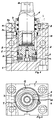
Die Erfindung ist in den Fig. 1 und 2 näher erläutert.
Der Blockzylinder besteht aus einem Gehäuse 1, in dem eine
zylindrische Bohrung 2 und eine Gewindebohrung 3 eingebracht sind.
Die Gewindebohrung 3 ist unterteilt in den mit einem Innengewinde
versehenen oberen Teil 3a und in einen sich zur Zylinderbohrung 2 hin
verjüngenden Teil 3b. In der zylindrischen Bohrung 2 ist der Kolben 5
geführt. Dem Kolben 5 ist eine Kolbenstange 6 zugeordnet, deren
Querschnitt der eines Polygons entspricht. Das Polygon ist hier
dreiecksförmig dargestellt, es kann auch in Form eines Polygon-Vierecks
oder Polygon-Fünfecks ausgebildet sein. Die Form der Kolbenstange 6
entspricht der Form eines regelmäßigen Polygons, bei dem alle Seiten
und Winkel kongruent sind.The block cylinder consists of a housing 1 in which one
Die polygonförmige Kolbenstange 6 ist in einer Führungsbuchse 7
geführt. Die Führungsbuchse 7 ist somit in ihrem Inneren dem Polygon
angepaßt und weist Dichtungen 8 in Form von Abstreifern auf, die die
Kolbenstange 6 gegen die Innenwandung der Führungsbuchse
abdichten. Dazu sind in der Innenwandung der Führungsbuchse Nuten
eingebracht, die dem Polygon-Querscnitt entsprechen und in die die
Dichtungen einlegbar sind. Die Dichtungen 8 weisen hierbei die gleiche
Polygon-Form wie Kolbenstange und Führungsbuchse auf. Eine
zusätzliche Außenabdichtung 9 sichert das ganze auch noch nach außen
ab.The
Die Führungsbuchse 7 ist mit einem Außengewinde 10 versehen, so daß
diese in den Gewindeteil 3a der Gewindebohrung 3 einschraubbar ist.
Die Führungsbuchse 7 wird unter großer Vorspannung eingeschraubt,
wodurch eine zusätzliche Verdrehsicherung gegeben ist.
Dementsprechend ist die Führungsbuchse 7 in ihrem unteren Teil 11
ebenfalls verjüngt, zur Einpassung in das Gehäuse 1. Die Kolbenstange
6 ist an ihrem herausragenden Ende 12 konisch ausgebildet zur
besseren Aufnahme der Werkzeuge. Damit lassen sich Torsionsmomente
besser übertragen und die Werkzeuge können in ihrer Winkelstellung
leichter eingestellt werden. Die Konusausführung 12 ist jedoch nur eine
der Möglichkeiten zur Werkzeugaufnahme. Jede andere Art zur
Aufnahme der Werkzeuge ist hier anbringbar, wie Gewindebefestigung,
Bohrungen mit Querstiften usw.The guide bush 7 is provided with an
Die in das Gehäuse 1 eingeschraubte Führungsbuchse 7 wird
zweckmässig festgesetzt, so daß ein unbeabsichtigtes Herausdrehen
unmöglich ist. Dazu sind in der Führungsbuchse 7 drei Aussparungen 13
vorgesehen, die einmal dazu dienen, um die Führungsbuchse 7 in das
Gehäuse fest eindrehen zu können und die zum anderen in mindest einer
der Aussparungen durch eine Klemmvorrichtung 4 festsetzbar sind.
Damit werden auf die Kolbenstange übertragene Torsionsmomente am
Gehäuse 1 bereits abgefangen.The guide bush 7 screwed into the housing 1
appropriately fixed so that unintentional unscrewing
is impossible. For this purpose, there are three
Bei Bearbeitungsvorgängen ist es oft erforderlich die Stellung der
Werkzeuge zu kennen und gegebenenfalls die Werkzeuge zu fixieren.
Dazu dienen Magnetsensoren 14 die im Kolben eingebracht sind. Diese
Magnetsensorne 14 machen somitjede Hubbewegung des Kolbens 5 mit
und geben ein Signal ab, das der jeweiligen Kolbenstellung entspricht.
Damit ist auch die Stellung der Werkzeuge erkennbar und diese lassen
sich wirksam auf den jeweiligen Bearbeitungsvorgang einstellen. Kolben
5 und Kolbenstange 6 sind formschlüssig mit einander verbunden. Der
Blockzylinder bildet somit insgesamt eine steife drehsichere Ausführung
von Kolben und Kolbenstange, so daß auf die Kolbenstange aufgesetzte
Werkzeuge exakt, drehsicher geführt sind und damit jegliche Arbeit
verrichten können.The position of the is often required for machining operations
Knowing tools and, if necessary, fixing the tools.
Claims (8)
Applications Claiming Priority (2)
| Application Number | Priority Date | Filing Date | Title |
|---|---|---|---|
| DE19752671 | 1997-11-28 | ||
| DE1997152671 DE19752671B4 (en) | 1997-11-28 | 1997-11-28 | Block cylinder for holding and guiding tools on a machine tool or on a work table |
Publications (2)
| Publication Number | Publication Date |
|---|---|
| EP0919729A2 true EP0919729A2 (en) | 1999-06-02 |
| EP0919729A3 EP0919729A3 (en) | 2002-01-16 |
Family
ID=7850027
Family Applications (1)
| Application Number | Title | Priority Date | Filing Date |
|---|---|---|---|
| EP98117095A Withdrawn EP0919729A3 (en) | 1997-11-28 | 1998-09-10 | Cylinder with antirotationally guided piston rod |
Country Status (2)
| Country | Link |
|---|---|
| EP (1) | EP0919729A3 (en) |
| DE (1) | DE19752671B4 (en) |
Cited By (3)
| Publication number | Priority date | Publication date | Assignee | Title |
|---|---|---|---|---|
| CN104613044A (en) * | 2015-01-28 | 2015-05-13 | 张汉桥 | Hydraulic cylinder assembly |
| US9281775B2 (en) | 2011-09-19 | 2016-03-08 | Ludwig Ehrhardt Gmbh | Clamping device with an electric motor |
| CN114215817A (en) * | 2021-12-17 | 2022-03-22 | 建湖县八达液压机械有限公司 | Hydraulic cylinder protection device and hydraulic cylinder with same |
Families Citing this family (2)
| Publication number | Priority date | Publication date | Assignee | Title |
|---|---|---|---|---|
| DE102016010657A1 (en) | 2016-09-02 | 2018-03-08 | Ludwig Ehrhardt Gmbh | Clamping device with a sensor arrangement |
| CN109058218B (en) * | 2018-08-28 | 2020-02-14 | 佛山市云峰精密机械有限公司 | Buffer piston cylinder for servo tool turret and servo tool turret |
Citations (4)
| Publication number | Priority date | Publication date | Assignee | Title |
|---|---|---|---|---|
| CH448645A (en) * | 1965-12-13 | 1967-12-15 | Festo Maschf Stoll G | Working cylinder with a reciprocating piston |
| DE2519251A1 (en) * | 1975-04-30 | 1976-11-11 | Reinhold Pilzecker | Working appliance with piston and cylinder - has piston rod and cylinder aperture of non-circular section to prevent turning |
| US4445840A (en) * | 1982-06-11 | 1984-05-01 | Kohtaki & Co., Ltd. | Pressure cylinder apparatus and hydraulic press incorporating the same |
| DE3738151A1 (en) * | 1986-11-13 | 1988-05-26 | Ckd Corp | PISTON POSITION DETECTOR FOR PRESSURE CYLINDER |
Family Cites Families (8)
| Publication number | Priority date | Publication date | Assignee | Title |
|---|---|---|---|---|
| DE7232039U (en) * | 1973-01-04 | Klopfer A Gmbh | Tool holding device | |
| US3603213A (en) * | 1969-03-12 | 1971-09-07 | Pneumo Dynamics Corp | Bushing-restrictor |
| DE2225009A1 (en) * | 1971-08-11 | 1973-02-15 | Federal Screw Works | HOLDER FOR A REAR GROOVING TOOL FOR AUTOMATIC SCREW BARS OR THE LIKE |
| DE3427124A1 (en) * | 1983-07-23 | 1985-01-31 | Hermann Dipl.-Ing. 7140 Ludwigsburg Kastner | Divisible tool for machining |
| DE3435964A1 (en) * | 1984-09-29 | 1986-04-10 | Teja 7814 Breisach Winterhalter | Cylinder with piston rod locked against rotation |
| EP0611623B1 (en) * | 1993-02-19 | 1996-04-17 | Alfred H. Schütte GmbH & Co. KG. | Fixing attachment |
| DE19500137A1 (en) * | 1995-01-04 | 1996-07-11 | Beetz Hydraulik Gmbh | Fluid-operated cylinder-piston arrangement with a magnetic field sensor |
| DE19530131C1 (en) * | 1995-08-16 | 1996-09-05 | Spinner Werkzeugmaschinenfabri | Fluid-operated clamping device for workpiece or tool |
-
1997
- 1997-11-28 DE DE1997152671 patent/DE19752671B4/en not_active Expired - Lifetime
-
1998
- 1998-09-10 EP EP98117095A patent/EP0919729A3/en not_active Withdrawn
Patent Citations (4)
| Publication number | Priority date | Publication date | Assignee | Title |
|---|---|---|---|---|
| CH448645A (en) * | 1965-12-13 | 1967-12-15 | Festo Maschf Stoll G | Working cylinder with a reciprocating piston |
| DE2519251A1 (en) * | 1975-04-30 | 1976-11-11 | Reinhold Pilzecker | Working appliance with piston and cylinder - has piston rod and cylinder aperture of non-circular section to prevent turning |
| US4445840A (en) * | 1982-06-11 | 1984-05-01 | Kohtaki & Co., Ltd. | Pressure cylinder apparatus and hydraulic press incorporating the same |
| DE3738151A1 (en) * | 1986-11-13 | 1988-05-26 | Ckd Corp | PISTON POSITION DETECTOR FOR PRESSURE CYLINDER |
Cited By (4)
| Publication number | Priority date | Publication date | Assignee | Title |
|---|---|---|---|---|
| US9281775B2 (en) | 2011-09-19 | 2016-03-08 | Ludwig Ehrhardt Gmbh | Clamping device with an electric motor |
| CN104613044A (en) * | 2015-01-28 | 2015-05-13 | 张汉桥 | Hydraulic cylinder assembly |
| CN114215817A (en) * | 2021-12-17 | 2022-03-22 | 建湖县八达液压机械有限公司 | Hydraulic cylinder protection device and hydraulic cylinder with same |
| CN114215817B (en) * | 2021-12-17 | 2024-03-01 | 建湖县八达液压机械有限公司 | Hydraulic cylinder with protection device |
Also Published As
| Publication number | Publication date |
|---|---|
| DE19752671A1 (en) | 1999-06-02 |
| DE19752671B4 (en) | 2006-11-23 |
| EP0919729A3 (en) | 2002-01-16 |
Similar Documents
| Publication | Publication Date | Title |
|---|---|---|
| DE60204741T2 (en) | Arrangement of pneumatic modules | |
| EP0715083B1 (en) | Rodless fluid cylinder | |
| EP2708327B1 (en) | Tensioning device for extending a threaded bolt, and tool suitable for this purpose, preferably drive adapter | |
| DE8505017U1 (en) | HYDRAULIC OR PNEUMATIC WORK CYLINDER | |
| DE3535426C2 (en) | Coupling device in a double lock cylinder | |
| EP0252208B2 (en) | Pressure fluid driven cylinder | |
| DE202009002899U1 (en) | tensioning device | |
| DE102008006045A1 (en) | tablet press | |
| EP0919729A2 (en) | Cylinder with antirotationally guided piston rod | |
| DE60004112T2 (en) | Locking device for a door, in particular for a glass door | |
| EP0772746B1 (en) | Positioning drive, in particular for a machine tool | |
| DE102009046037B4 (en) | chuck | |
| EP1660262B1 (en) | Interface of a tool | |
| DE3025156A1 (en) | Punching press with locking plates - has clamping cylinder-operated locking elements engaging with slot in tool bottom parts | |
| DE2522560C3 (en) | Pressure medium-operated actuator with a working piston that can be moved back and forth in a straight cylinder | |
| DE2631119A1 (en) | RUBBER CLOTHING DEVICE | |
| DE2706940C2 (en) | Hydraulic drill rig | |
| DE3324334A1 (en) | OPENING DEVICE FOR A DRILL ROD OF A DRILLING SYSTEM WITH EXTENSIBLE DRILL ROD | |
| EP0046977B1 (en) | Hydraulically actuated stretching device for stretching saw blades in a gang saw | |
| DE3734987C1 (en) | Cutting rotor with interchangeable knife bars for shredding solid materials | |
| DE3140837A1 (en) | DIE CASTING MACHINE | |
| DE4312275C2 (en) | Reel changer with a working cylinder | |
| DE3707066A1 (en) | Clamping device for attaching a dressing to the cylinder of a rotary printing machine | |
| DE2156633C3 (en) | Piston-cylinder arrangement with a multi-part piston | |
| DE10352548A1 (en) | Work-piece clamping unit, comprising complementary parts positioned in bores facing each other |
Legal Events
| Date | Code | Title | Description |
|---|---|---|---|
| PUAI | Public reference made under article 153(3) epc to a published international application that has entered the european phase |
Free format text: ORIGINAL CODE: 0009012 |
|
| AK | Designated contracting states |
Kind code of ref document: A2 Designated state(s): AT BE CH CY DE DK ES FI FR GB GR IE IT LI LU MC NL PT SE Kind code of ref document: A2 Designated state(s): DE FR GB IT |
|
| AX | Request for extension of the european patent |
Free format text: AL;LT;LV;MK;RO;SI |
|
| PUAL | Search report despatched |
Free format text: ORIGINAL CODE: 0009013 |
|
| AK | Designated contracting states |
Kind code of ref document: A3 Designated state(s): AT BE CH CY DE DK ES FI FR GB GR IE IT LI LU MC NL PT SE |
|
| AX | Request for extension of the european patent |
Free format text: AL;LT;LV;MK;RO;SI |
|
| 17P | Request for examination filed |
Effective date: 20020710 |
|
| AKX | Designation fees paid |
Free format text: DE FR GB IT |
|
| 17Q | First examination report despatched |
Effective date: 20030313 |
|
| STAA | Information on the status of an ep patent application or granted ep patent |
Free format text: STATUS: THE APPLICATION IS DEEMED TO BE WITHDRAWN |
|
| 18D | Application deemed to be withdrawn |
Effective date: 20030724 |