EP0909942B1 - Appareil pour l'aspiration d'un échantillon gazeux d'une enceinte de gaz industriel sous vide - Google Patents
Appareil pour l'aspiration d'un échantillon gazeux d'une enceinte de gaz industriel sous vide Download PDFInfo
- Publication number
- EP0909942B1 EP0909942B1 EP98203406A EP98203406A EP0909942B1 EP 0909942 B1 EP0909942 B1 EP 0909942B1 EP 98203406 A EP98203406 A EP 98203406A EP 98203406 A EP98203406 A EP 98203406A EP 0909942 B1 EP0909942 B1 EP 0909942B1
- Authority
- EP
- European Patent Office
- Prior art keywords
- probe
- gas
- process gas
- vacuum pump
- filter
- Prior art date
- Legal status (The legal status is an assumption and is not a legal conclusion. Google has not performed a legal analysis and makes no representation as to the accuracy of the status listed.)
- Expired - Lifetime
Links
- 239000000523 sample Substances 0.000 claims abstract description 52
- 238000000034 method Methods 0.000 claims abstract description 46
- 239000002245 particle Substances 0.000 claims abstract description 8
- 238000007872 degassing Methods 0.000 claims description 14
- 229910000831 Steel Inorganic materials 0.000 claims description 11
- 239000010959 steel Substances 0.000 claims description 11
- 239000007787 solid Substances 0.000 claims description 7
- 239000004744 fabric Substances 0.000 claims description 2
- 238000010926 purge Methods 0.000 claims 4
- 229920000914 Metallic fiber Polymers 0.000 claims 1
- 238000004868 gas analysis Methods 0.000 abstract description 7
- 238000011010 flushing procedure Methods 0.000 abstract description 2
- 238000002360 preparation method Methods 0.000 abstract 1
- 239000007789 gas Substances 0.000 description 68
- 238000011001 backwashing Methods 0.000 description 9
- 239000007788 liquid Substances 0.000 description 6
- 238000001816 cooling Methods 0.000 description 5
- 239000000203 mixture Substances 0.000 description 4
- XLYOFNOQVPJJNP-UHFFFAOYSA-N water Substances O XLYOFNOQVPJJNP-UHFFFAOYSA-N 0.000 description 4
- 238000000605 extraction Methods 0.000 description 3
- 238000005070 sampling Methods 0.000 description 3
- 239000006096 absorbing agent Substances 0.000 description 2
- 238000004458 analytical method Methods 0.000 description 2
- 239000004568 cement Substances 0.000 description 2
- 238000002485 combustion reaction Methods 0.000 description 2
- 238000009833 condensation Methods 0.000 description 2
- 230000005494 condensation Effects 0.000 description 2
- 230000003750 conditioning effect Effects 0.000 description 2
- 239000011094 fiberboard Substances 0.000 description 2
- 239000000463 material Substances 0.000 description 2
- 238000005259 measurement Methods 0.000 description 2
- 238000010943 off-gassing Methods 0.000 description 2
- 230000001105 regulatory effect Effects 0.000 description 2
- 230000000717 retained effect Effects 0.000 description 2
- 238000007789 sealing Methods 0.000 description 2
- 239000000126 substance Substances 0.000 description 2
- OGBQILNBLMPPDP-UHFFFAOYSA-N 2,3,4,7,8-Pentachlorodibenzofuran Chemical compound O1C2=C(Cl)C(Cl)=C(Cl)C=C2C2=C1C=C(Cl)C(Cl)=C2 OGBQILNBLMPPDP-UHFFFAOYSA-N 0.000 description 1
- 229910001111 Fine metal Inorganic materials 0.000 description 1
- 206010040007 Sense of oppression Diseases 0.000 description 1
- 238000004140 cleaning Methods 0.000 description 1
- 239000007859 condensation product Substances 0.000 description 1
- 238000001514 detection method Methods 0.000 description 1
- 238000001914 filtration Methods 0.000 description 1
- 238000011835 investigation Methods 0.000 description 1
- 238000004519 manufacturing process Methods 0.000 description 1
- 239000002184 metal Substances 0.000 description 1
- 229910052751 metal Inorganic materials 0.000 description 1
- 238000012544 monitoring process Methods 0.000 description 1
- 239000000047 product Substances 0.000 description 1
- 239000000565 sealant Substances 0.000 description 1
- 239000004753 textile Substances 0.000 description 1
- 230000002110 toxicologic effect Effects 0.000 description 1
- 231100000027 toxicology Toxicity 0.000 description 1
- 238000009849 vacuum degassing Methods 0.000 description 1
- 238000009423 ventilation Methods 0.000 description 1
Images
Classifications
-
- G—PHYSICS
- G01—MEASURING; TESTING
- G01N—INVESTIGATING OR ANALYSING MATERIALS BY DETERMINING THEIR CHEMICAL OR PHYSICAL PROPERTIES
- G01N33/00—Investigating or analysing materials by specific methods not covered by groups G01N1/00 - G01N31/00
- G01N33/0004—Gaseous mixtures, e.g. polluted air
- G01N33/0009—General constructional details of gas analysers, e.g. portable test equipment
- G01N33/0027—General constructional details of gas analysers, e.g. portable test equipment concerning the detector
- G01N33/0029—Cleaning of the detector
-
- C—CHEMISTRY; METALLURGY
- C21—METALLURGY OF IRON
- C21C—PROCESSING OF PIG-IRON, e.g. REFINING, MANUFACTURE OF WROUGHT-IRON OR STEEL; TREATMENT IN MOLTEN STATE OF FERROUS ALLOYS
- C21C5/00—Manufacture of carbon-steel, e.g. plain mild steel, medium carbon steel or cast steel or stainless steel
- C21C5/28—Manufacture of steel in the converter
- C21C5/42—Constructional features of converters
- C21C5/46—Details or accessories
- C21C5/4673—Measuring and sampling devices
-
- C—CHEMISTRY; METALLURGY
- C21—METALLURGY OF IRON
- C21C—PROCESSING OF PIG-IRON, e.g. REFINING, MANUFACTURE OF WROUGHT-IRON OR STEEL; TREATMENT IN MOLTEN STATE OF FERROUS ALLOYS
- C21C7/00—Treating molten ferrous alloys, e.g. steel, not covered by groups C21C1/00 - C21C5/00
- C21C7/10—Handling in a vacuum
-
- G—PHYSICS
- G01—MEASURING; TESTING
- G01N—INVESTIGATING OR ANALYSING MATERIALS BY DETERMINING THEIR CHEMICAL OR PHYSICAL PROPERTIES
- G01N1/00—Sampling; Preparing specimens for investigation
- G01N1/02—Devices for withdrawing samples
- G01N1/22—Devices for withdrawing samples in the gaseous state
- G01N1/2226—Sampling from a closed space, e.g. food package, head space
-
- G—PHYSICS
- G01—MEASURING; TESTING
- G01N—INVESTIGATING OR ANALYSING MATERIALS BY DETERMINING THEIR CHEMICAL OR PHYSICAL PROPERTIES
- G01N33/00—Investigating or analysing materials by specific methods not covered by groups G01N1/00 - G01N31/00
- G01N33/0004—Gaseous mixtures, e.g. polluted air
- G01N33/0009—General constructional details of gas analysers, e.g. portable test equipment
- G01N33/0011—Sample conditioning
-
- G—PHYSICS
- G01—MEASURING; TESTING
- G01N—INVESTIGATING OR ANALYSING MATERIALS BY DETERMINING THEIR CHEMICAL OR PHYSICAL PROPERTIES
- G01N1/00—Sampling; Preparing specimens for investigation
- G01N1/02—Devices for withdrawing samples
- G01N1/22—Devices for withdrawing samples in the gaseous state
- G01N1/2202—Devices for withdrawing samples in the gaseous state involving separation of sample components during sampling
-
- G—PHYSICS
- G01—MEASURING; TESTING
- G01N—INVESTIGATING OR ANALYSING MATERIALS BY DETERMINING THEIR CHEMICAL OR PHYSICAL PROPERTIES
- G01N1/00—Sampling; Preparing specimens for investigation
- G01N1/02—Devices for withdrawing samples
- G01N1/22—Devices for withdrawing samples in the gaseous state
- G01N1/24—Suction devices
-
- G—PHYSICS
- G01—MEASURING; TESTING
- G01N—INVESTIGATING OR ANALYSING MATERIALS BY DETERMINING THEIR CHEMICAL OR PHYSICAL PROPERTIES
- G01N1/00—Sampling; Preparing specimens for investigation
- G01N1/02—Devices for withdrawing samples
- G01N1/22—Devices for withdrawing samples in the gaseous state
- G01N1/2202—Devices for withdrawing samples in the gaseous state involving separation of sample components during sampling
- G01N2001/222—Other features
- G01N2001/2223—Other features aerosol sampling devices
Definitions
- the invention relates to a method and a device for taking samples from a process gas room for detection the outgassing of liquid steel, being in a process gas space a probe with a filter protrudes and the Outgassing using a dry, multi-stage Vacuum pump are sucked off.
- Vacuum degassing takes place in the manufacture of steel of molten steel use to avoid unwanted contained in steel Remove or reduce inclusions. there becomes, for example, one filled with liquid steel Pour ladle into a vacuum chamber and about 20 minutes degassed.
- For monitoring the degassing process becomes an analysis of the gas present in the vacuum chamber sought, if possible during the entire degassing process takes place continuously.
- the approximately 500 ° C hot gas from the Gas chamber of the vacuum chamber usually by means of a Vacuum the portable gas analyzer belonging to the vacuum pump.
- this method only allows a discontinuous one Measurement and gas analysis.
- the suction devices known from these publications have not proven themselves in practice and do not allow sufficiently accurate gas analysis; in particular because none are continuously the same or too small Amount of gas is removed from the process gas space if this from atmospheric pressure to negative pressure up to about 1 mbar is brought.
- the vacuum pump does not only need measuring gas can extract from such a high vacuum space, but also be suitable for all occurring pressure conditions an equal amount of gas throughout Extract the degassing time and feed it directly to the analyzer.
- the vacuum pumps provided for this in the publications are not suitable for this.
- the filters easily clogged, which also affects the gas flow becomes. To falsify the sample gas composition it can be done with common oil-lubricated vacuum pumps due to oil vapors entering the sample gas u.
- the invention further assumes that in DE 36 04 206 A1 a multi-stage, dry-running rotary vane vacuum pump is described, which operates without oil and delivers absolutely oil-free gases and products.
- a multi-stage, dry-running rotary vane vacuum pump is described, which operates without oil and delivers absolutely oil-free gases and products.
- German published patent application 42 05 792 A1 is one Device for taking samples from the resulting exhaust gases a combustion process in terms of toxicological and ecological to be regarded as particularly harmful Substances PCDD and PCDF known.
- This sampling takes place under at least atmospheric pressure instead, in which disclosed a suctioned partial flow of the exhaust gas passed gas analysis through a filter and an absorber and can then be determined quantitatively.
- Filter and absorber materials in complex Way is unlocked, taking the cartridge out of the measuring system removed and replaced with a new one and initially only a collection of the residues in the cartridge takes place, so there is no continuous sampling is possible with an immediate gas analysis.
- the invention has for its object a method and a suction device according to claim 1 train that a continuous extraction of sample gas is possible during the entire process. Moreover the suction device should be such that during during the breaks in treatment by cleaning the measurements Compressed air flushing is possible.
- the process gas space can be, for example, the vacuum chamber for degassing liquid steel, a pouring ladle filled with liquid steel being placed in the vacuum chamber. After the vacuum chamber has been closed, it is placed under vacuum with a water or steam jet pump, the pressure being reduced to about 1 mbar.
- the degassing process usually takes about 20 minutes.
- the process gas changes its composition during the process. In the case of steel degassing, the proportion of O 2 , CO, CO 2 , N 2 , H 2 and Ar is of particular interest. B. can be done by means of a mass spectrometer.
- the process gas space is used for continuous gas analysis Sample gas continuously taken.
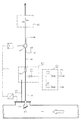
- a probe is used for removal 2, which protrudes into the process gas space 1.
- This is on hers Provide suction opening with a filter 3, which is temperature resistant and is designed to have solid particles withstands more than 4 ⁇ m.
- a filter 3 which is temperature resistant and is designed to have solid particles withstands more than 4 ⁇ m.
- the filter material must be obtained in this way be that on the one hand it brings about the desired filtering, on the other hand, it has sufficient conductivity and can be easily cleaned by backwashing the usually takes place after each degassing process.
- the mouth of the probe runs obliquely, the the upper part protrudes further inwards and the opening above covers. As a result, the process gas may become Solid particles entrained upwards and falling down again prevented from being deposited on the filter surface.
- An essential part of the suction device is a Pump connected to the probe 2 via a suction line 4 5, the type of a dry running multi-stage vacuum pump and generates a negative pressure of up to about 0.5 mbar.
- the pump 5 promotes what is sucked out of the process gas space 1
- Sample gas through a sample gas conditioning device, from the for example, a sample gas cooler 6 is shown in the drawing is to a gas analyzer, e.g. B. a mass spectrometer.
- the speed of the pump 5 is determined by a Speed control device 7 as a function of that in the process gas space 1 prevailing pressure regulated so that continuously an equal amount of sample gas, e.g. B. two liters per minute, is suctioned off.
- the dry running vacuum pump is as a multi-stage z. B. three-stage rotary piston machine executed, the rotary lobes provided with sealing strips are and therefore run dry, so no sealing liquid need. It is provided with water cooling 8.
- Ball valve 9 arranged one in the open position has practically throttle-free flow cross-section. Moreover is to the suction line 4 between this ball valve 9 and the probe 2 a pressurizing the probe 2 with compressed air Backwashing device 10 connected. Between the Backwashing device 10 and the suction line 4 is for shut-off purposes another ball valve 11 is present. To suck to avoid leakage gas, the ball valves 9, 11 expediently arranged in a closed housing 15, connected to the process gas chamber 1 via a pipeline 16 is, so that these valves from the outside the process gas pressure subject.
- a third ball valve 12 connected to a compressed air line 13 connects, and a shut-off valve serving for ventilation 14 shown.
- the ball valve is used to clean probe 2 9 closed, and after opening the ball valves 11.12 acts the pulsating generated by the ball valve 12 Compressed air z. B. with 10 bar on the filter 3 and rinses this free of fixed solid particles. hereby the free flow cross section of filter 3 is retained, which is particularly critical in the vacuum area.
- the ball valves 9, 11 and 12 are controlled by an electronic control device posed.
- the ball valve 12 is controlled that the pressure pulsates by z. B. compressed air and Block phase six times in succession with 10 seconds each, the backwashing process is therefore approximately 120 seconds.
Landscapes
- Chemical & Material Sciences (AREA)
- Engineering & Computer Science (AREA)
- Health & Medical Sciences (AREA)
- Life Sciences & Earth Sciences (AREA)
- General Physics & Mathematics (AREA)
- Pathology (AREA)
- Immunology (AREA)
- Physics & Mathematics (AREA)
- Analytical Chemistry (AREA)
- Biochemistry (AREA)
- General Health & Medical Sciences (AREA)
- Food Science & Technology (AREA)
- Medicinal Chemistry (AREA)
- Combustion & Propulsion (AREA)
- Materials Engineering (AREA)
- Metallurgy (AREA)
- Organic Chemistry (AREA)
- Manufacturing & Machinery (AREA)
- Biomedical Technology (AREA)
- Molecular Biology (AREA)
- Sampling And Sample Adjustment (AREA)
Claims (5)
- Procédé pour le prélèvement d'échantillons dans une chambre à gaz opératoire pour constater les émanations gazeuses d'acier liquide, une sonde avec un filtre étant insérée dans une chambre à gaz opératoire et les émanations gazeuses étant aspirées au moyen d'une pompe à vide à plusieurs échelons fonctionnant à sec,
caractérisé en ce que
les gaz à mesurer sont aspirés dans une chambre à gaz opératoire sous vide et acheminés directement par l'intermédiaire d'une installation de traitement des gaz à un appareil d'analyse gazeuse, la sonde (2) étant munie d'un filtre (3) résistant à la température, retenant les particules solides > 4 µm et un premier robinet hémisphérique (9) étant utilisé dans la conduite d'aspiration entre la sonde (2) et la pompe à vide (5) pour interrompre la liaison entre la sonde (2) et la pompe à vide (5) et la sonde étant sollicitée à l'air comprimé par un système de nettoyage (10) au moyen d'un deuxième robinet hémisphérique (11). - Procédé pour l'application du procédé de la revendication 1 pour l'aspiration d'un gaz brûlant à mesurer dans une chambre à gaz opératoire, en particulier pour le dégazage d'acier liquide, consistant en une sonde insérée dans la chambre à gaz opératoire, une pompe à vide à plusieurs échelons, fonctionnant à sec, aspirant le gaz à mesurer par l'intermédiaire d'une installation de traitement du gaz et en un filtre traversé par le gaz à mesurer,
caractérisé en ce que
la chambre à gaz opératoire est sous vide et que la sonde (2) est pourvue d'un filtre (3) résistant à la température, retenant les particules solides de taille supérieure à 4 µm, qu'un robinet hémisphérique (9) est installé dans la conduite d'aspiration (4) entre la sonde (2) et la pompe à vide (5), qu'à la conduite d'aspiration (4) entre la sonde (2) et le robinet hémisphérique (9), un système de nettoyage (10) sollicitant la sonde (2) à l'air comprimé est raccordé avec branchement intermédiaire d'un autre robinet hémisphérique (11) et que le gaz à mesurer est acheminé par l'intermédiaire d'une installation de traitement du gaz à un appareil d'analyse gazeuse. - Dispositif selon la revendication 2,
caractérisé en ce que
le filtre (3) est constitué d'une toile métallique ou d'une plaque métallique fibreuse. - Dispositif selon la revendication 2 ou 3,
caractérisé en ce que
le régime de la pompe à vide (5) est réglable en fonction de la pression dans la chambre à gaz opératoire (1). - Dispositif selon une des revendications 2 à 4,
caractérisé en ce que
les robinets hémisphériques (9, 11) installés dans la conduite d'aspiration et dans la conduite d'accès au système de nettoyage (10) sont disposés dans un boítier fermé (15) qui est connecté par une canalisation (16) à la chambre à gaz opératoire (1).
Applications Claiming Priority (2)
| Application Number | Priority Date | Filing Date | Title |
|---|---|---|---|
| DE19745808 | 1997-10-16 | ||
| DE19745808A DE19745808C1 (de) | 1997-10-16 | 1997-10-16 | Vorrichtung zum Absaugen eines Meßgases aus einem unter Vakuum stehenden Prozessgasraumes |
Publications (2)
| Publication Number | Publication Date |
|---|---|
| EP0909942A1 EP0909942A1 (fr) | 1999-04-21 |
| EP0909942B1 true EP0909942B1 (fr) | 2002-09-25 |
Family
ID=7845771
Family Applications (1)
| Application Number | Title | Priority Date | Filing Date |
|---|---|---|---|
| EP98203406A Expired - Lifetime EP0909942B1 (fr) | 1997-10-16 | 1998-10-12 | Appareil pour l'aspiration d'un échantillon gazeux d'une enceinte de gaz industriel sous vide |
Country Status (3)
| Country | Link |
|---|---|
| EP (1) | EP0909942B1 (fr) |
| AT (1) | ATE225034T1 (fr) |
| DE (2) | DE19745808C1 (fr) |
Cited By (1)
| Publication number | Priority date | Publication date | Assignee | Title |
|---|---|---|---|---|
| US12066361B2 (en) | 2018-11-15 | 2024-08-20 | Holcim Technology Ltd | Method for analyzing samples of a gas in a rotary cement kiln |
Families Citing this family (4)
| Publication number | Priority date | Publication date | Assignee | Title |
|---|---|---|---|---|
| FI116161B (fi) * | 2002-12-23 | 2005-09-30 | Outokumpu Oy | Menetelmä ja laitteisto kaasun koostumuksen mittaamiseksi leijupedistä |
| US6862915B2 (en) | 2003-03-20 | 2005-03-08 | Rosemount Analytical Inc. | Oxygen analyzer with enhanced calibration and blow-back |
| DE102006050771A1 (de) * | 2006-10-27 | 2008-04-30 | Sms Mevac Gmbh | Verfahren und Vorrichtung zum Überwachen, Steuern und/oder Regeln des Spritzverhaltens einer Metallschmelze |
| CN114414748B (zh) * | 2022-03-24 | 2022-07-01 | 南京戈里斯环保科技有限公司 | 一种挥发性有机物含量检测装置及方法 |
Citations (2)
| Publication number | Priority date | Publication date | Assignee | Title |
|---|---|---|---|---|
| DE2745957A1 (de) * | 1977-10-12 | 1979-04-19 | Du Pont | Chemisches dosimeter |
| DE4205792A1 (de) * | 1992-02-26 | 1993-09-02 | Gfa Ges Fuer Arbeitsplatz Und | Verfahren und vorrichtung zur probenahme aus abgasen |
Family Cites Families (8)
| Publication number | Priority date | Publication date | Assignee | Title |
|---|---|---|---|---|
| US3520657A (en) * | 1965-12-27 | 1970-07-14 | Dravo Corp | Method and apparatus for the analysis of off-gases in a refining process |
| US3748906A (en) * | 1970-10-15 | 1973-07-31 | Jones & Laughlin Steel Corp | Gas sampling apparatus |
| JPS5442324A (en) * | 1977-09-10 | 1979-04-04 | Nisshin Steel Co Ltd | Control procedure of steel making process using mass spectrometer |
| US4586367A (en) * | 1984-03-19 | 1986-05-06 | Horiba Instruments Incorporated | Proportional exhaust sampler and control means |
| DE3604206A1 (de) * | 1986-02-11 | 1987-08-13 | Provac Gmbh & Co | Trockenlaufende drehschieber-vakuumpumpe |
| DE3706742A1 (de) * | 1987-02-28 | 1988-09-08 | Salzgitter Peine Stahlwerke | Verfahren und vorrichtung zur entgasungsbehandlung einer stahlschmelze in einer vakuumanlage |
| US5205177A (en) * | 1991-01-23 | 1993-04-27 | Research-Cottrell, Inc. | Method and apparatus for gas monitoring |
| DE9105354U1 (de) * | 1991-04-30 | 1992-06-04 | Siemens AG, 8000 München | Einrichtung zur Aufbereitung von mit Rußpartikeln beladenen Abgasen für die Analyse |
-
1997
- 1997-10-16 DE DE19745808A patent/DE19745808C1/de not_active Expired - Fee Related
-
1998
- 1998-10-12 EP EP98203406A patent/EP0909942B1/fr not_active Expired - Lifetime
- 1998-10-12 AT AT98203406T patent/ATE225034T1/de not_active IP Right Cessation
- 1998-10-12 DE DE59805669T patent/DE59805669D1/de not_active Expired - Fee Related
Patent Citations (2)
| Publication number | Priority date | Publication date | Assignee | Title |
|---|---|---|---|---|
| DE2745957A1 (de) * | 1977-10-12 | 1979-04-19 | Du Pont | Chemisches dosimeter |
| DE4205792A1 (de) * | 1992-02-26 | 1993-09-02 | Gfa Ges Fuer Arbeitsplatz Und | Verfahren und vorrichtung zur probenahme aus abgasen |
Cited By (1)
| Publication number | Priority date | Publication date | Assignee | Title |
|---|---|---|---|---|
| US12066361B2 (en) | 2018-11-15 | 2024-08-20 | Holcim Technology Ltd | Method for analyzing samples of a gas in a rotary cement kiln |
Also Published As
| Publication number | Publication date |
|---|---|
| DE19745808C1 (de) | 1998-12-10 |
| ATE225034T1 (de) | 2002-10-15 |
| EP0909942A1 (fr) | 1999-04-21 |
| DE59805669D1 (de) | 2002-10-31 |
Similar Documents
| Publication | Publication Date | Title |
|---|---|---|
| EP0291630B1 (fr) | Procédé et appareil pour prétraiter un gaz à analyser | |
| DE69128794T2 (de) | Teilchenüberwachungseinrichtung in dieselabgasen | |
| DE2920195A1 (de) | Sonde zur probennahme von rauchschachtgasen oder anderen industriellen gasen | |
| DE69310570T2 (de) | Verfahren und Vorrichtung zum Einleiten und Regeln von komprimierten Gasen für eine Verunreinigungsanalyse | |
| DD256373A5 (de) | Verfahren und Vorrichtung zur kontinuierlichen Entnahme einer heißen Gasprobe aus einem Reaktionsraum für eine Gasanalyse | |
| DE724723T1 (de) | System zur feststellung von no-pegeln in ausgeatmeter luft und diagnostische verfahren für zu abnormalen no-pegeln in beziehung stehenden abweichungen | |
| DE602005002031T2 (de) | Adaptor für gerät zur entnahme kleinvolumiger luftproben | |
| EP0909942B1 (fr) | Appareil pour l'aspiration d'un échantillon gazeux d'une enceinte de gaz industriel sous vide | |
| DE102007059485A1 (de) | Lösungsvorrichtung | |
| AT412424B (de) | Vorrichtung und verfahren zur analyse von abgaskomponenten | |
| EP0390942B1 (fr) | Système de mesure de l'émission de poussière dans les conduites contenant des poussières dangereuses, en particulier dans les cheminées | |
| DE102010010112B4 (de) | Vorrichtung zur selektiven Bestimmung der Menge von Ölnebel oder Aerosolen | |
| EP3327689A1 (fr) | Élément de guidage d'air | |
| DE1598177C3 (fr) | ||
| DE60122490T2 (de) | Probenentnahmegerät zur beseitigung von partikelartefakten bei der rauchgasmessung | |
| DE19531595C2 (de) | Verfahren und Vorrichtung zur Bestimmung des Dioxingehaltes eines Gasstromes | |
| WO2020187461A1 (fr) | Dispositif d'encollage à chaud pour une étiqueteuse comprenant une aspiration | |
| DE4211225C2 (de) | Partikelgehalt-Überwachungseinrichtung | |
| DE10162278A1 (de) | Verfahren zur Detektion von flüssigen Komponenten in einem Aerosolstrom | |
| DE102008056515B4 (de) | Wägezelle und Verfahren zum Abdichten einer Wägezelle | |
| DE102011108445A1 (de) | Messverfahren und Messanordnung für Verunreinigungen der Ladeluft eines Abgasturboladers | |
| GB2259982A (en) | Sampling a fluid to determine its contaminant content | |
| EP1833601A1 (fr) | Procede et dispositif de prelevement et d'analyse d'echantillons | |
| DE19820174A1 (de) | Verfahren und Vorrichtung zur Abscheidung von Aerosolen | |
| WO2020148030A1 (fr) | Dispositif pour le prélèvement d'un échantillon d'haleine sous forme gazeuse d'une personne testée |
Legal Events
| Date | Code | Title | Description |
|---|---|---|---|
| PUAI | Public reference made under article 153(3) epc to a published international application that has entered the european phase |
Free format text: ORIGINAL CODE: 0009012 |
|
| AK | Designated contracting states |
Kind code of ref document: A1 Designated state(s): AT BE DE ES FR GB IT LU NL SE |
|
| AX | Request for extension of the european patent |
Free format text: AL;LT;LV;MK;RO;SI |
|
| RTI1 | Title (correction) | ||
| RIN1 | Information on inventor provided before grant (corrected) |
Inventor name: KUSKE, GUENTER |
|
| 17P | Request for examination filed |
Effective date: 19990928 |
|
| AKX | Designation fees paid |
Free format text: AT BE DE ES FR GB IT LU NL SE |
|
| RBV | Designated contracting states (corrected) |
Designated state(s): AT BE DE ES FR GB IT LU NL SE |
|
| RAP1 | Party data changed (applicant data changed or rights of an application transferred) |
Owner name: MANNESMANN AG Owner name: KUSKE GMBH |
|
| RIN1 | Information on inventor provided before grant (corrected) |
Inventor name: CLASEN KLAUS-D. DIPL.-ING. Inventor name: REIDICK HERMANN DIPL.-ING. Inventor name: KUSKE, GUENTER |
|
| 17Q | First examination report despatched |
Effective date: 20010402 |
|
| GRAG | Despatch of communication of intention to grant |
Free format text: ORIGINAL CODE: EPIDOS AGRA |
|
| GRAG | Despatch of communication of intention to grant |
Free format text: ORIGINAL CODE: EPIDOS AGRA |
|
| GRAH | Despatch of communication of intention to grant a patent |
Free format text: ORIGINAL CODE: EPIDOS IGRA |
|
| GRAH | Despatch of communication of intention to grant a patent |
Free format text: ORIGINAL CODE: EPIDOS IGRA |
|
| GRAA | (expected) grant |
Free format text: ORIGINAL CODE: 0009210 |
|
| AK | Designated contracting states |
Kind code of ref document: B1 Designated state(s): AT BE DE ES FR GB IT LU NL SE |
|
| PG25 | Lapsed in a contracting state [announced via postgrant information from national office to epo] |
Ref country code: NL Free format text: LAPSE BECAUSE OF FAILURE TO SUBMIT A TRANSLATION OF THE DESCRIPTION OR TO PAY THE FEE WITHIN THE PRESCRIBED TIME-LIMIT Effective date: 20020925 Ref country code: IT Free format text: LAPSE BECAUSE OF FAILURE TO SUBMIT A TRANSLATION OF THE DESCRIPTION OR TO PAY THE FEE WITHIN THE PRESCRIBED TIME-LIMIT;WARNING: LAPSES OF ITALIAN PATENTS WITH EFFECTIVE DATE BEFORE 2007 MAY HAVE OCCURRED AT ANY TIME BEFORE 2007. THE CORRECT EFFECTIVE DATE MAY BE DIFFERENT FROM THE ONE RECORDED. Effective date: 20020925 Ref country code: GB Free format text: LAPSE BECAUSE OF FAILURE TO SUBMIT A TRANSLATION OF THE DESCRIPTION OR TO PAY THE FEE WITHIN THE PRESCRIBED TIME-LIMIT Effective date: 20020925 |
|
| REF | Corresponds to: |
Ref document number: 225034 Country of ref document: AT Date of ref document: 20021015 Kind code of ref document: T |
|
| REG | Reference to a national code |
Ref country code: GB Ref legal event code: FG4D Free format text: NOT ENGLISH |
|
| PG25 | Lapsed in a contracting state [announced via postgrant information from national office to epo] |
Ref country code: BE Free format text: LAPSE BECAUSE OF NON-PAYMENT OF DUE FEES Effective date: 20021031 |
|
| REF | Corresponds to: |
Ref document number: 59805669 Country of ref document: DE Date of ref document: 20021031 |
|
| PG25 | Lapsed in a contracting state [announced via postgrant information from national office to epo] |
Ref country code: SE Free format text: LAPSE BECAUSE OF FAILURE TO SUBMIT A TRANSLATION OF THE DESCRIPTION OR TO PAY THE FEE WITHIN THE PRESCRIBED TIME-LIMIT Effective date: 20021225 |
|
| NLV1 | Nl: lapsed or annulled due to failure to fulfill the requirements of art. 29p and 29m of the patents act | ||
| GBV | Gb: ep patent (uk) treated as always having been void in accordance with gb section 77(7)/1977 [no translation filed] |
Effective date: 20020925 |
|
| ET | Fr: translation filed | ||
| PG25 | Lapsed in a contracting state [announced via postgrant information from national office to epo] |
Ref country code: ES Free format text: LAPSE BECAUSE OF FAILURE TO SUBMIT A TRANSLATION OF THE DESCRIPTION OR TO PAY THE FEE WITHIN THE PRESCRIBED TIME-LIMIT Effective date: 20030328 |
|
| BERE | Be: lapsed |
Owner name: *MANNESMANN A.G. Effective date: 20021031 Owner name: *KUSKE G.M.B.H. Effective date: 20021031 |
|
| PLBE | No opposition filed within time limit |
Free format text: ORIGINAL CODE: 0009261 |
|
| STAA | Information on the status of an ep patent application or granted ep patent |
Free format text: STATUS: NO OPPOSITION FILED WITHIN TIME LIMIT |
|
| 26N | No opposition filed |
Effective date: 20030626 |
|
| PGFP | Annual fee paid to national office [announced via postgrant information from national office to epo] |
Ref country code: AT Payment date: 20061023 Year of fee payment: 9 |
|
| PGFP | Annual fee paid to national office [announced via postgrant information from national office to epo] |
Ref country code: LU Payment date: 20061124 Year of fee payment: 9 |
|
| PGFP | Annual fee paid to national office [announced via postgrant information from national office to epo] |
Ref country code: DE Payment date: 20061221 Year of fee payment: 9 |
|
| PG25 | Lapsed in a contracting state [announced via postgrant information from national office to epo] |
Ref country code: DE Free format text: LAPSE BECAUSE OF NON-PAYMENT OF DUE FEES Effective date: 20080501 |
|
| PG25 | Lapsed in a contracting state [announced via postgrant information from national office to epo] |
Ref country code: AT Free format text: LAPSE BECAUSE OF NON-PAYMENT OF DUE FEES Effective date: 20071012 |
|
| REG | Reference to a national code |
Ref country code: FR Ref legal event code: ST Effective date: 20080630 |
|
| PGFP | Annual fee paid to national office [announced via postgrant information from national office to epo] |
Ref country code: FR Payment date: 20061020 Year of fee payment: 9 |
|
| PG25 | Lapsed in a contracting state [announced via postgrant information from national office to epo] |
Ref country code: FR Free format text: LAPSE BECAUSE OF NON-PAYMENT OF DUE FEES Effective date: 20071031 |
|
| PG25 | Lapsed in a contracting state [announced via postgrant information from national office to epo] |
Ref country code: LU Free format text: LAPSE BECAUSE OF NON-PAYMENT OF DUE FEES Effective date: 20071012 |