EP0909942B1 - Device for aspiration of a gas sample from a process-gas enclosure under vacuum - Google Patents
Device for aspiration of a gas sample from a process-gas enclosure under vacuum Download PDFInfo
- Publication number
- EP0909942B1 EP0909942B1 EP98203406A EP98203406A EP0909942B1 EP 0909942 B1 EP0909942 B1 EP 0909942B1 EP 98203406 A EP98203406 A EP 98203406A EP 98203406 A EP98203406 A EP 98203406A EP 0909942 B1 EP0909942 B1 EP 0909942B1
- Authority
- EP
- European Patent Office
- Prior art keywords
- probe
- gas
- process gas
- vacuum pump
- filter
- Prior art date
- Legal status (The legal status is an assumption and is not a legal conclusion. Google has not performed a legal analysis and makes no representation as to the accuracy of the status listed.)
- Expired - Lifetime
Links
- 239000000523 sample Substances 0.000 claims abstract description 52
- 238000000034 method Methods 0.000 claims abstract description 46
- 239000002245 particle Substances 0.000 claims abstract description 8
- 238000007872 degassing Methods 0.000 claims description 14
- 229910000831 Steel Inorganic materials 0.000 claims description 11
- 239000010959 steel Substances 0.000 claims description 11
- 239000007787 solid Substances 0.000 claims description 7
- 239000004744 fabric Substances 0.000 claims description 2
- 238000010926 purge Methods 0.000 claims 4
- 229920000914 Metallic fiber Polymers 0.000 claims 1
- 238000004868 gas analysis Methods 0.000 abstract description 7
- 238000011010 flushing procedure Methods 0.000 abstract description 2
- 238000002360 preparation method Methods 0.000 abstract 1
- 239000007789 gas Substances 0.000 description 68
- 238000011001 backwashing Methods 0.000 description 9
- 239000007788 liquid Substances 0.000 description 6
- 238000001816 cooling Methods 0.000 description 5
- 239000000203 mixture Substances 0.000 description 4
- XLYOFNOQVPJJNP-UHFFFAOYSA-N water Substances O XLYOFNOQVPJJNP-UHFFFAOYSA-N 0.000 description 4
- 238000000605 extraction Methods 0.000 description 3
- 238000005070 sampling Methods 0.000 description 3
- 239000006096 absorbing agent Substances 0.000 description 2
- 238000004458 analytical method Methods 0.000 description 2
- 239000004568 cement Substances 0.000 description 2
- 238000002485 combustion reaction Methods 0.000 description 2
- 238000009833 condensation Methods 0.000 description 2
- 230000005494 condensation Effects 0.000 description 2
- 230000003750 conditioning effect Effects 0.000 description 2
- 239000011094 fiberboard Substances 0.000 description 2
- 239000000463 material Substances 0.000 description 2
- 238000005259 measurement Methods 0.000 description 2
- 238000010943 off-gassing Methods 0.000 description 2
- 230000001105 regulatory effect Effects 0.000 description 2
- 230000000717 retained effect Effects 0.000 description 2
- 238000007789 sealing Methods 0.000 description 2
- 239000000126 substance Substances 0.000 description 2
- OGBQILNBLMPPDP-UHFFFAOYSA-N 2,3,4,7,8-Pentachlorodibenzofuran Chemical compound O1C2=C(Cl)C(Cl)=C(Cl)C=C2C2=C1C=C(Cl)C(Cl)=C2 OGBQILNBLMPPDP-UHFFFAOYSA-N 0.000 description 1
- 229910001111 Fine metal Inorganic materials 0.000 description 1
- 206010040007 Sense of oppression Diseases 0.000 description 1
- 238000004140 cleaning Methods 0.000 description 1
- 239000007859 condensation product Substances 0.000 description 1
- 238000001514 detection method Methods 0.000 description 1
- 238000001914 filtration Methods 0.000 description 1
- 238000011835 investigation Methods 0.000 description 1
- 238000004519 manufacturing process Methods 0.000 description 1
- 239000002184 metal Substances 0.000 description 1
- 229910052751 metal Inorganic materials 0.000 description 1
- 238000012544 monitoring process Methods 0.000 description 1
- 239000000047 product Substances 0.000 description 1
- 239000000565 sealant Substances 0.000 description 1
- 239000004753 textile Substances 0.000 description 1
- 230000002110 toxicologic effect Effects 0.000 description 1
- 231100000027 toxicology Toxicity 0.000 description 1
- 238000009849 vacuum degassing Methods 0.000 description 1
- 238000009423 ventilation Methods 0.000 description 1
Images
Classifications
-
- G—PHYSICS
- G01—MEASURING; TESTING
- G01N—INVESTIGATING OR ANALYSING MATERIALS BY DETERMINING THEIR CHEMICAL OR PHYSICAL PROPERTIES
- G01N33/00—Investigating or analysing materials by specific methods not covered by groups G01N1/00 - G01N31/00
- G01N33/0004—Gaseous mixtures, e.g. polluted air
- G01N33/0009—General constructional details of gas analysers, e.g. portable test equipment
- G01N33/0027—General constructional details of gas analysers, e.g. portable test equipment concerning the detector
- G01N33/0029—Cleaning of the detector
-
- C—CHEMISTRY; METALLURGY
- C21—METALLURGY OF IRON
- C21C—PROCESSING OF PIG-IRON, e.g. REFINING, MANUFACTURE OF WROUGHT-IRON OR STEEL; TREATMENT IN MOLTEN STATE OF FERROUS ALLOYS
- C21C5/00—Manufacture of carbon-steel, e.g. plain mild steel, medium carbon steel or cast steel or stainless steel
- C21C5/28—Manufacture of steel in the converter
- C21C5/42—Constructional features of converters
- C21C5/46—Details or accessories
- C21C5/4673—Measuring and sampling devices
-
- C—CHEMISTRY; METALLURGY
- C21—METALLURGY OF IRON
- C21C—PROCESSING OF PIG-IRON, e.g. REFINING, MANUFACTURE OF WROUGHT-IRON OR STEEL; TREATMENT IN MOLTEN STATE OF FERROUS ALLOYS
- C21C7/00—Treating molten ferrous alloys, e.g. steel, not covered by groups C21C1/00 - C21C5/00
- C21C7/10—Handling in a vacuum
-
- G—PHYSICS
- G01—MEASURING; TESTING
- G01N—INVESTIGATING OR ANALYSING MATERIALS BY DETERMINING THEIR CHEMICAL OR PHYSICAL PROPERTIES
- G01N1/00—Sampling; Preparing specimens for investigation
- G01N1/02—Devices for withdrawing samples
- G01N1/22—Devices for withdrawing samples in the gaseous state
- G01N1/2226—Sampling from a closed space, e.g. food package, head space
-
- G—PHYSICS
- G01—MEASURING; TESTING
- G01N—INVESTIGATING OR ANALYSING MATERIALS BY DETERMINING THEIR CHEMICAL OR PHYSICAL PROPERTIES
- G01N33/00—Investigating or analysing materials by specific methods not covered by groups G01N1/00 - G01N31/00
- G01N33/0004—Gaseous mixtures, e.g. polluted air
- G01N33/0009—General constructional details of gas analysers, e.g. portable test equipment
- G01N33/0011—Sample conditioning
-
- G—PHYSICS
- G01—MEASURING; TESTING
- G01N—INVESTIGATING OR ANALYSING MATERIALS BY DETERMINING THEIR CHEMICAL OR PHYSICAL PROPERTIES
- G01N1/00—Sampling; Preparing specimens for investigation
- G01N1/02—Devices for withdrawing samples
- G01N1/22—Devices for withdrawing samples in the gaseous state
- G01N1/2202—Devices for withdrawing samples in the gaseous state involving separation of sample components during sampling
-
- G—PHYSICS
- G01—MEASURING; TESTING
- G01N—INVESTIGATING OR ANALYSING MATERIALS BY DETERMINING THEIR CHEMICAL OR PHYSICAL PROPERTIES
- G01N1/00—Sampling; Preparing specimens for investigation
- G01N1/02—Devices for withdrawing samples
- G01N1/22—Devices for withdrawing samples in the gaseous state
- G01N1/24—Suction devices
-
- G—PHYSICS
- G01—MEASURING; TESTING
- G01N—INVESTIGATING OR ANALYSING MATERIALS BY DETERMINING THEIR CHEMICAL OR PHYSICAL PROPERTIES
- G01N1/00—Sampling; Preparing specimens for investigation
- G01N1/02—Devices for withdrawing samples
- G01N1/22—Devices for withdrawing samples in the gaseous state
- G01N1/2202—Devices for withdrawing samples in the gaseous state involving separation of sample components during sampling
- G01N2001/222—Other features
- G01N2001/2223—Other features aerosol sampling devices
Definitions
- the invention relates to a method and a device for taking samples from a process gas room for detection the outgassing of liquid steel, being in a process gas space a probe with a filter protrudes and the Outgassing using a dry, multi-stage Vacuum pump are sucked off.
- Vacuum degassing takes place in the manufacture of steel of molten steel use to avoid unwanted contained in steel Remove or reduce inclusions. there becomes, for example, one filled with liquid steel Pour ladle into a vacuum chamber and about 20 minutes degassed.
- For monitoring the degassing process becomes an analysis of the gas present in the vacuum chamber sought, if possible during the entire degassing process takes place continuously.
- the approximately 500 ° C hot gas from the Gas chamber of the vacuum chamber usually by means of a Vacuum the portable gas analyzer belonging to the vacuum pump.
- this method only allows a discontinuous one Measurement and gas analysis.
- the suction devices known from these publications have not proven themselves in practice and do not allow sufficiently accurate gas analysis; in particular because none are continuously the same or too small Amount of gas is removed from the process gas space if this from atmospheric pressure to negative pressure up to about 1 mbar is brought.
- the vacuum pump does not only need measuring gas can extract from such a high vacuum space, but also be suitable for all occurring pressure conditions an equal amount of gas throughout Extract the degassing time and feed it directly to the analyzer.
- the vacuum pumps provided for this in the publications are not suitable for this.
- the filters easily clogged, which also affects the gas flow becomes. To falsify the sample gas composition it can be done with common oil-lubricated vacuum pumps due to oil vapors entering the sample gas u.
- the invention further assumes that in DE 36 04 206 A1 a multi-stage, dry-running rotary vane vacuum pump is described, which operates without oil and delivers absolutely oil-free gases and products.
- a multi-stage, dry-running rotary vane vacuum pump is described, which operates without oil and delivers absolutely oil-free gases and products.
- German published patent application 42 05 792 A1 is one Device for taking samples from the resulting exhaust gases a combustion process in terms of toxicological and ecological to be regarded as particularly harmful Substances PCDD and PCDF known.
- This sampling takes place under at least atmospheric pressure instead, in which disclosed a suctioned partial flow of the exhaust gas passed gas analysis through a filter and an absorber and can then be determined quantitatively.
- Filter and absorber materials in complex Way is unlocked, taking the cartridge out of the measuring system removed and replaced with a new one and initially only a collection of the residues in the cartridge takes place, so there is no continuous sampling is possible with an immediate gas analysis.
- the invention has for its object a method and a suction device according to claim 1 train that a continuous extraction of sample gas is possible during the entire process. Moreover the suction device should be such that during during the breaks in treatment by cleaning the measurements Compressed air flushing is possible.
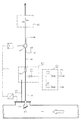
- the process gas space can be, for example, the vacuum chamber for degassing liquid steel, a pouring ladle filled with liquid steel being placed in the vacuum chamber. After the vacuum chamber has been closed, it is placed under vacuum with a water or steam jet pump, the pressure being reduced to about 1 mbar.
- the degassing process usually takes about 20 minutes.
- the process gas changes its composition during the process. In the case of steel degassing, the proportion of O 2 , CO, CO 2 , N 2 , H 2 and Ar is of particular interest. B. can be done by means of a mass spectrometer.
- the process gas space is used for continuous gas analysis Sample gas continuously taken.
- a probe is used for removal 2, which protrudes into the process gas space 1.
- This is on hers Provide suction opening with a filter 3, which is temperature resistant and is designed to have solid particles withstands more than 4 ⁇ m.
- a filter 3 which is temperature resistant and is designed to have solid particles withstands more than 4 ⁇ m.
- the filter material must be obtained in this way be that on the one hand it brings about the desired filtering, on the other hand, it has sufficient conductivity and can be easily cleaned by backwashing the usually takes place after each degassing process.
- the mouth of the probe runs obliquely, the the upper part protrudes further inwards and the opening above covers. As a result, the process gas may become Solid particles entrained upwards and falling down again prevented from being deposited on the filter surface.
- An essential part of the suction device is a Pump connected to the probe 2 via a suction line 4 5, the type of a dry running multi-stage vacuum pump and generates a negative pressure of up to about 0.5 mbar.
- the pump 5 promotes what is sucked out of the process gas space 1
- Sample gas through a sample gas conditioning device, from the for example, a sample gas cooler 6 is shown in the drawing is to a gas analyzer, e.g. B. a mass spectrometer.
- the speed of the pump 5 is determined by a Speed control device 7 as a function of that in the process gas space 1 prevailing pressure regulated so that continuously an equal amount of sample gas, e.g. B. two liters per minute, is suctioned off.
- the dry running vacuum pump is as a multi-stage z. B. three-stage rotary piston machine executed, the rotary lobes provided with sealing strips are and therefore run dry, so no sealing liquid need. It is provided with water cooling 8.
- Ball valve 9 arranged one in the open position has practically throttle-free flow cross-section. Moreover is to the suction line 4 between this ball valve 9 and the probe 2 a pressurizing the probe 2 with compressed air Backwashing device 10 connected. Between the Backwashing device 10 and the suction line 4 is for shut-off purposes another ball valve 11 is present. To suck to avoid leakage gas, the ball valves 9, 11 expediently arranged in a closed housing 15, connected to the process gas chamber 1 via a pipeline 16 is, so that these valves from the outside the process gas pressure subject.
- a third ball valve 12 connected to a compressed air line 13 connects, and a shut-off valve serving for ventilation 14 shown.
- the ball valve is used to clean probe 2 9 closed, and after opening the ball valves 11.12 acts the pulsating generated by the ball valve 12 Compressed air z. B. with 10 bar on the filter 3 and rinses this free of fixed solid particles. hereby the free flow cross section of filter 3 is retained, which is particularly critical in the vacuum area.
- the ball valves 9, 11 and 12 are controlled by an electronic control device posed.
- the ball valve 12 is controlled that the pressure pulsates by z. B. compressed air and Block phase six times in succession with 10 seconds each, the backwashing process is therefore approximately 120 seconds.
Landscapes
- Chemical & Material Sciences (AREA)
- Engineering & Computer Science (AREA)
- Health & Medical Sciences (AREA)
- Life Sciences & Earth Sciences (AREA)
- General Physics & Mathematics (AREA)
- Pathology (AREA)
- Immunology (AREA)
- Physics & Mathematics (AREA)
- Analytical Chemistry (AREA)
- Biochemistry (AREA)
- General Health & Medical Sciences (AREA)
- Food Science & Technology (AREA)
- Medicinal Chemistry (AREA)
- Combustion & Propulsion (AREA)
- Materials Engineering (AREA)
- Metallurgy (AREA)
- Organic Chemistry (AREA)
- Manufacturing & Machinery (AREA)
- Biomedical Technology (AREA)
- Molecular Biology (AREA)
- Sampling And Sample Adjustment (AREA)
Abstract
Description
Die Erfindung betrifft ein Verfahren und eine Vorrichtung zur Probeentnahme aus einem Prozessgasraum zur Feststellung der Ausgasungen von flüssigem Stahl, wobei in einen Prozessgasraum eine Sonde mit einem Filter hineinragt und die Ausgasungen mittels einer trockenlaufenden, mehrstufigen Vakuumpumpe abgesaugt werden.The invention relates to a method and a device for taking samples from a process gas room for detection the outgassing of liquid steel, being in a process gas space a probe with a filter protrudes and the Outgassing using a dry, multi-stage Vacuum pump are sucked off.
Bei der Herstellung von Stahl findet eine Vakuumentgasung des flüssigen Stahls Verwendung, um im Stahl enthaltene unerwünschte Einschlüsse zu entfernen oder zu verringern. Dabei wird beispielsweise eine mit flüssigem Stahl gefüllte Gießpfanne in eine Vakuumkammer gestellt und etwa 20 Minuten entgast. Für eine Überwachung des Entgasungsprozeßes wird eine Analyse des in der Vakuumkammer vorhandenen Gases angestrebt, die möglichst während des gesamten Entgasungsvorganges kontinuierlich stattfindet. Für Untersuchungszwecke ist es bekannt, das etwa 500°C heiße Meßgas aus dem Gasraum der Vakuumkammer mittels einer einem in der Regel transportablen Gasanalysegerät zugehörigen Vakuumpumpe abzusaugen. Diese Methode erlaubt jedoch nur eine diskontinuierliche Meßung und Gasanalyse. Aus der DE 28 39 315 A1 und der US 3 520 657 ist bekannt, aus dem Abgas der Vakuumanlage Meßgas abzusaugen, dieses zu analysieren und mit Hilfe der Analysedaten die Entgasung zu steuern. Hierfür ist ein in den Abgaskanal ragendes Saugrohr vorgesehen, das über einen außerhalb des Abgaskanals angeordneten Filter mit einer Vakuumpumpe verbunden ist, welche das abgesaugte Meßgas einem Analysegerät zuführt. Eine ähnliche Steuereinrichtung ist auch aus der DE 37 06 742 A1 bekannt, bei der ein von einer Vakuumpumpe aus der Abgasleitung abgesaugter Gasstrom zunächst durch eine Kühleinrichtung und eine Filtereinrichtung gesaugt und dann von dem von der Vakuumpumpe verdichteten Gasstrom ein Teilstrom mittels einer weiteren Förderpumpe über zusätzliche Filter unmittelbar dem Analysegerät zugeführt wird. Die aus diesen Druckschriften bekannten Absaugvorrichtungen haben sich jedoch in der Praxis nicht bewährt und erlauben keine ausreichend genaue Gasanalyse; insbesondere weil keine fortlaufend gleiche oder eine zu geringe Menge Gas aus dem Prozessgasraum abgeführt wird, wenn dieser von Atmosphärmdruck auf einen Unterdruck bis etwa 1 mbar gebracht wird. Die Vakuumpumpe muß aber nicht nur Meßgas aus einem derart hohen Unterdruckraum absaugen können, sondern auch geeignet sein, bei allen vorkommenden Druckverhältnissen eine gleiche Menge Gas während der gesamten Entgasungszeit abzusaugen und unmittelbar dem Analysegerät zuzuführen. Die in den Druckschriften hierfür vorgesehenen Vakuumpumpen sind hierfür nicht geeignet. Desweiteren werden die Filter leicht verstopft, wodurch die Gasströmung ebenfalls beeinträchtigt wird. Zu einer Verfälschung der Meßgaszusammensetzung kann es bei üblichen ölgeschmierten Vakuumpumpen durch in das Meßgas gelangende Öldämpfe u. dgl. kommen, aber auch bei einer eventuellen Kondensation von Gasbestandteilen, die bei diesen Unterdrücken in der vor dem Filter bereits abgekühlten Meßgasleitung erfolgen kann, wobei die Kondensationsprodukte an den Feststoffteilchen haften und im Filter zurückgehalten werden. Soweit bei den bekannten Absaugeinrichtungen Filter und Filterpatronen vorgesehen sind, ist zudem deren häufiger Austausch umständlich und aufwendig. Zur Gasentnahme aus einem Drehrohr-Zementofen ist in der DE 35 45 491 C2 eine Gasabsaugvorrichtung mit einer wassergekühlten Sonde und einem zugänglichen Filter beschrieben, der ebenfalls austauschbare Filterpatronen benötigt. Da aufgrund der Verbrennungs- und Umsetzungsprozesse im Zementdrehrohrofen an der Gasentnahmestelle Überdruck herrscht, ist eine solche Gasabsaugvorrichtung nicht zum Absaugen heißer Meßgase geeignet, die unter Vakuum stehen. Vacuum degassing takes place in the manufacture of steel of molten steel use to avoid unwanted contained in steel Remove or reduce inclusions. there becomes, for example, one filled with liquid steel Pour ladle into a vacuum chamber and about 20 minutes degassed. For monitoring the degassing process becomes an analysis of the gas present in the vacuum chamber sought, if possible during the entire degassing process takes place continuously. For investigation purposes it is known that the approximately 500 ° C hot gas from the Gas chamber of the vacuum chamber usually by means of a Vacuum the portable gas analyzer belonging to the vacuum pump. However, this method only allows a discontinuous one Measurement and gas analysis. From DE 28 39 315 A1 and US 3,520,657 is known from the exhaust gas of the vacuum system Aspirate sample gas, analyze it and with the help control the degassing of the analysis data. For this is an provided in the exhaust duct protruding intake pipe, which a filter arranged outside the exhaust duct with a Vacuum pump is connected, which is the extracted gas feeds to an analyzer. A similar control device is also known from DE 37 06 742 A1, in which one of a vacuum pump extracted from the exhaust pipe Gas flow first through a cooling device and a filter device sucked and then from that of the vacuum pump compressed gas stream a partial stream by means of another Feed pump fed directly to the analyzer via additional filters becomes. The suction devices known from these publications have not proven themselves in practice and do not allow sufficiently accurate gas analysis; in particular because none are continuously the same or too small Amount of gas is removed from the process gas space if this from atmospheric pressure to negative pressure up to about 1 mbar is brought. The vacuum pump does not only need measuring gas can extract from such a high vacuum space, but also be suitable for all occurring pressure conditions an equal amount of gas throughout Extract the degassing time and feed it directly to the analyzer. The vacuum pumps provided for this in the publications are not suitable for this. Furthermore, the filters easily clogged, which also affects the gas flow becomes. To falsify the sample gas composition it can be done with common oil-lubricated vacuum pumps due to oil vapors entering the sample gas u. the like, but also in the event of any condensation of gas components, those with these oppressions in the before Filter already cooled sample gas line can take place the condensation products adhere to the solid particles and retained in the filter. So far with the known Suction devices, filters and filter cartridges are provided their frequent exchange is cumbersome and expensive. For gas extraction from a rotary kiln cement kiln is a gas extraction device in DE 35 45 491 C2 with a water-cooled probe and an accessible Filter described, the also replaceable filter cartridges needed. Because of the combustion and implementation processes in the cement rotary kiln at the gas sampling point Such gas suction device is overpressure not suitable for extracting hot measuring gases to be under vacuum.
Die Erfindung geht weiterhin davon aus, dass in der DE 36 04 206 A1 eine mehrstufige, trocken laufende Drehschieber-Vakuumpumpe beschrieben ist, welche schmierölfrei betrieben wird und absolut ölfreie Gase und Produkte liefert. Die Verwendung dieser Vakuumpumpen zum Absaugen heißer Meßgase aus einem unter Vakuum stehenden Prozeßgasraum, insbesondere einer Vakuumkammer zur Entgasung von flüssigem Stahl ist bisher nicht bekannt und auch nicht ohne weiteres möglich.The invention further assumes that in DE 36 04 206 A1 a multi-stage, dry-running rotary vane vacuum pump is described, which operates without oil and delivers absolutely oil-free gases and products. The Use of these vacuum pumps to extract hot measuring gases from a process gas space under vacuum, in particular a vacuum chamber for degassing liquid steel not yet known and not possible without further ado.
Aus der deutschen Offenlegungsschrift 42 05 792 A1 ist eine
Vorrichtung zur Probenentnahme aus den entstehenden Abgasen
eines Verbrennungsprozesses im Hinblick auf die toxikologische
und ökologische als besonders schädlich anzusehenden
Substanzen PCDD und PCDF bekannt. Diese Probenentnahme findet
unter zumindest Atmosphärendruck statt, wobei in dem
offenbarten Verfahren ein abgesaugter Teilstrom des Abgases
gasanalytisch über einen Filter und einen Absorber geleitet
wird und anschließend quantitativ bestimmt werden kann.
Hierzu ist es notwendig, dass das in der Katusche 10 eingeschlossene
Filter- und Absorbermaterialien in aufwendiger
Weise aufgeschlossen wird, wobei die Katusche aus dem Messsystem
entfernt und durch eine neue ersetzt werden muss und
zunächst nur eine Sammlung der Rückstände in der Katusche
stattfindet, sodass keine kontinuierliche Probenentnahme
mit einer sofortigen Gasanalyse möglich ist.From German published patent application 42 05 792 A1 is one
Device for taking samples from the resulting exhaust gases
a combustion process in terms of toxicological
and ecological to be regarded as particularly harmful
Substances PCDD and PCDF known. This sampling takes place
under at least atmospheric pressure instead, in which
disclosed a suctioned partial flow of the exhaust gas
passed gas analysis through a filter and an absorber
and can then be determined quantitatively.
For this purpose, it is necessary that that enclosed in the
Der Erfindung liegt die Aufgabe zugrunde, ein Verfahren und eine Absaugvorrichtung gemäß dem des Anspruches 1 derart auszubilden, dass eine kontinuierliche Entnahme von Messgas während der gesamten Prozessdauer möglich ist. Außerdem soll die Absaugvorrichtung so beschaffen sein, dass während der Behandlungspausen eine Reinigung der Messungen durch Druckluftspülung möglich ist. The invention has for its object a method and a suction device according to claim 1 train that a continuous extraction of sample gas is possible during the entire process. Moreover the suction device should be such that during during the breaks in treatment by cleaning the measurements Compressed air flushing is possible.
Diese Aufgabe wird durch das Verfahren mit den Merkmalen
des Anspruchs 1 sowie durch die Vorrichtung mit den Merkmalen
des Anspruchs 2 gelöst. Bei dieser sind mehrere Bauteile,
nämlich Sonde, Filter, Vakuumpumpe und Rückspüleinrichtung
in einer solchen Weise angeordnet und aufeinander abgestimmt,
dass während der gesamten Prozeßdauer Meßgas aus
dem Prozeßgasraum bei allen Druckverhältnissen im Prozeßgasraum,
ohne Verfälschung der Zusammensetzung in einer
konstanten Gasmenge abgesaugt und dem Gasanalysegerät zugeführt
wird. Die Anordnung des Filters unmittelbar an der
Sonde bewirkt zunächst, dass keine Feststoffteilchen größer
als 4 µm mitgerissen werden und erst gar nicht in das Leitungssystem
der Absaugvorrichtung gelangen. Kombiniert ist
die Maßnahme mit einer Rückspüleinrichtung, durch welche
der Filter in bestimmten Zeitabständen z. B. nach jedem
Prozeß durch Rückspülung mit Druckluft gereinigt werden
kann. Diese Maßnahme wiederum ist durch die Anordnung von
Kugelhähnen in der Saugleitung und in der Anschlußleitung
der Rückspülleitung ergänzt, die für den Rückspülvorgang
einerseits die zur Vakuumpumpe führende Saugleitung absperrt
und die Rückspülleitung anschließt und die in ihrem
geöffneten Zustand einen praktisch ungeminderten Strömungsquerschnitt
gewährleisten. Die Verwendung einer trocken
laufenden mehrstufigen Vakuumpumpe hat zunächst den Vorteil,
daß die Zusammensetzung des abgesaugten Meßgases
durch keine Fremdstoffe, z. B. Dichtungsmittel, verfälscht
wird. Erst eine solche mehrstufige Pumpe ist geeignet, um
aus einem Prozessgasraum mit einem sehr niedrigen Gasdruck
von etwa 1 mbar Meßgas abzusaugen. Da trocken laufende,
mehrstufige Vakuumpumpen eine Wasserkühleinrichtung haben,
kann die Kühlung so eingestellt werden, daß selbst bei den
sehr niedrigen Drücken bis etwa 0,5 mbar keine Kondensation
von Meßgasbestandteilen stattfinden kann.This task is accomplished by the method with the characteristics
of
Wegen der relativ hohen Temperatur des Prozessgases kommen für den Filter Textilgewebe u. dgl. nicht in Betracht. Als besonders geeignet hat sich ein Filter aus einem entsprechend feinen Metallgewebe oder einer metallischen Faserplatte erwiesen.Because of the relatively high temperature of the process gas for the filter textile fabric u. Like. Not considered. As A filter made from a corresponding filter has been particularly suitable fine metal mesh or a metallic fiberboard proved.
Durch eine Regelung der Drehzahl der Pumpe in Abhängigkeit von dem Druck im Prozessgasraum ist eine Entnahme von Meßgas während des gesamten Entgasungsvorganges erreichbar, das heißt auch während des Auf- und Abbaus des Vakuums. Somit ist eine fortlaufende Gasanalyse über den ganzen Prozesszeitraum möglich, die wiederum mittels entsprechender Einrichtungen bedarfsweise eine Steuerung oder Regelung des Prozesses zuläßt.By regulating the speed of the pump depending on of the pressure in the process gas space is a removal of sample gas accessible during the entire degassing process, this also means when the vacuum is being built up and broken down. Consequently is a continuous gas analysis over the entire process period possible, which in turn by means of appropriate Facilities require control or regulation of the Process allows.
Um das Ansaugen von Leckgas zu verhindern, sind die in der Saugleitung bzw. in der Anschlußleitung der Rückspüleinrichtung angeordneten Kugelhähne in einem verschlossenen Gehäuse angeordnet, das über eine Rohrleitung an den Prozessgasraum angeschlossen ist.To prevent the leakage of gas from being sucked in, they are in the Suction line or in the connection line of the backwashing device arranged ball valves in a closed Housing arranged that via a pipe to the process gas space connected.
In der Zeichnung ist eine Vorrichtung zum Absaugen eines
Meßgases aus einem unter Vakuum stehenden Prozessgasraum 1
schematisch dargestellt. Der Prozessgasraum kann beispielsweise
die Vakuumkammer zur Entgasung von flüssigem Stahl
sein, wobei eine mit flüssigem Stahl gefüllte Gießpfanne in
die Vakuumkammer eingestellt wird. Nach dem Verschließen
der Vakuumkammer wird diese mit einer Wasser- oder
Dampfstrahlpumpe unter Vakuum gesetzt, wobei der Druck auf
etwa 1 mbar erniedrigt wird. Der Entgasungsprozess dauert
in der Regel etwa 20 Minuten. Das Prozessgas ändert während
des Prozesses seine Zusammensetzung. Bei einer Stahlentgasung
ist insbesondere der Anteil an O2, CO, CO2, N2, H2 und
Ar von Interesse, wobei die Analyse z. B. mittels eines
Massenspektrometers erfolgen kann.In the drawing, a device for extracting a measuring gas from a
Für eine kontinuierliche Gasanalyse wird dem Prozessgasraum
fortlaufend Meßgas entnommen. Der Entnahme dient eine Sonde
2, die in den Prozessgasraum 1 hineinragt. Diese ist an ihrer
Ansaugöffnung mit einem Filter 3 versehen, der temperaturbeständig
und so ausgebildet ist, daß er Feststoffteilchen
größer als 4 µm zurückhält. Geeignet ist beispielsweise
ein etwa 1 bis 3 mm dickes Metallgewebe oder eine metallische
Faserplatte. Das Filtermaterial muß so beschaffen
sein, daß es einerseits die erwünschte Filterung herbeiführt,
anderseits aber eine ausreichende Leitfähigkeit besitzt
und sich durch Rückspülung leicht reinigen läßt, die
in der Regel nach jedem Entgasungsvorgang stattfindet. Außerdem
verläuft die Mündung der Sonde schräg, wobei der
obere Teil weiter nach innen vorsteht und die Öffnung oben
abdeckt. Hierdurch werden von dem Prozessgas gegebenenfalls
nach oben mitgerissene und wieder nach unten fallende Feststoffteilchen
gehindert, sich auf der Filterfläche abzulagern.The process gas space is used for continuous gas analysis
Sample gas continuously taken. A probe is used for
Wesentlicher Bestandteil der Absaugvorrichtung ist eine
über eine Saugleitung 4 an die Sonde 2 angeschlossene Pumpe
5, die vom Typ einer trocken laufenden mehrstufigen Vakuumpumpe
ist und einen Unterdruck bis etwa 0,5 mbar erzeugt.
Die Pumpe 5 fördert das aus dem Prozessgasraum 1 abgesaugte
Meßgas durch eine Meßgasaufbereitungseinrichtung, von der
in der Zeichnung beispielsweise ein Meßgaskühler 6 dargestellt
ist, zu einem Gasanalysegerät, z. B. einem Massenspektrometer.
Die Drehzahl der Pumpe 5 wird durch eine
Drehzahlregelvorrichtung 7 in Abhängigkeit von dem im Prozessgasraum
1 herrschenden Druck derart geregelt, daß fortlaufend
eine gleich Menge Meßgas, z. B. zwei Liter pro Minute,
abgesaugt wird. Die trocken laufende Vakuumpumpe ist
als mehrstufige z. B. dreistufige Rotationskolbenmaschine
ausgeführt, deren Drehkolben mit Dichtungsleisten versehen
sind und daher trocken laufen, also keine Dichtungsflüssigkeit
benötigen. Sie ist mit einer Wasserkühlung 8 versehen.An essential part of the suction device is a
Pump connected to the
Um den Prozessgasraum 1 zwischen den Entgasungsprozessen
gegenüber der Meßgasaufbereitungseinrichtung abzusperren
und eine Reinigung der Sonde 2 vornehmen zu können, ist in
der Saugleitung 4 zwischen der Sonde 2 und der Pumpe 5 ein
Kugelhahn 9 angeordnet, der in der Offenstellung einen
praktisch drosselfreien Strömungsquerschnitt aufweist. Außerdem
ist an die Saugleitung 4 zwischen diesem Kugelhahn 9
und der Sonde 2 eine die Sonde 2 mit Druckluft beaufschlagende
Rückspüleinrichtung 10 angeschlossen. Zwischen der
Rückspüleinrichtung 10 und der Saugleitung 4 ist für Absperrzwecke
ein weiterer Kugelhahn 11 vorhanden. Um das Ansaugen
von Leckgas zu vermeiden, sind die Kugelhähne 9,11
zweckmäßig in einem verschlossenen Gehäuse 15 angeordnet,
das über eine Rohrleitung 16 an den Prozessgasraum 1 angeschlossen
ist, so daß diese Ventile von außen dem Prozessgasdruck
unterliegen. Als Teile der Rückspüleinrichtung 10
sind ein dritter Kugelhahn 12, der an eine Druckluftleitung
13 anschließt, und ein der Entlüftung dienendes Absperrventil
14 dargestellt. Zur Reinigung der Sonde 2 wird der Kugelhahn
9 geschlossen, und nach Öffnen der Kugelhähne 11,12
wirkt die durch den Kugelhahn 12 erzeugte pulsierende
Druckluft z. B. mit 10 bar auf den Filter 3 ein und spült
diesen von festgesetzten Feststoffteilchen frei. Hierdurch
bleibt der freie Strömungsquerschnitt des Filters 3 erhalten,
der im Vakuumbereich besonders kritisch ist. Die Kugelhähne
9,11 und 12 werden durch eine elektronische Steuereinrichtung
gestellt. Der Kugelhahn 12 wird so gesteuert,
daß der Druck pulsiert, indem z. B. Druckluft- und
Sperrphase mit je 10 Sekunden sechsmal aufeinander folgen,
der Rückspülvorgang mithin etwa 120 Sekunden beträgt. Around the
- 11
- ProzessgasraumProcess gas space
- 22
- Sondeprobe
- 33
- Filterfilter
- 44
- Saugleitungsuction
- 55
- Pumpepump
- 66
- Meßgaskühlergas cooler
- 77
- DrehzahlregelvorrichtungSpeed control device
- 88th
- Wasserkühlungwater cooling
- 99
- Kugelhahnball valve
- 1010
- Rückspüleinrichtungbackflushing
- 1111
- Kugelhahnball valve
- 1212
- Kugelhahnball valve
- 1313
- DruckluftleitungCompressed air line
- 1414
- Absperrventilshut-off valve
- 1515
- Gehäusecasing
- 1616
- Rohrleitungpipeline
Claims (5)
- A method of taking, from a process gas chamber, a sample for determining the degassing of molten steel whereby a probe with a filter projects into a process gas chamber and the degassing products are extracted by a dry running, multi-stage vacuum pump, characterised in that the gas samples are extracted from a process gas chamber, which has a negative pressure, and are directed straight to a gas analyser via a gas sample processing unit whereby the probe (2) is equipped with a temperature resistant filter (3) retaining solid particles > 4 µm and whereby, in the suction line between probe (2) and vacuum pump (5), a first ball valve (9) is used for closing the connection between probe (2) and vacuum pump (5) and, via a second ball valve (11), compressed air is applied to the probe by a purging apparatus (10).
- An apparatus for the application of the method according to claim 1 for extracting a hot gas sample from a process gas chamber, in particular for the degassing of molten steel, comprising a probe projecting into the process gas chamber, a dry running, multi-stage vacuum pump extracting the gas sample via a gas sample processing unit, and a filter through which the gas sample flows, characterised in that the process gas chamber is under vacuum and that probe (2) is equipped with a temperature resistant filter (3) retaining solid particles > 4 µm, that a ball valve (9) is located in the suction line (4) between probe (2) and vacuum pump (5), that a purging apparatus (10) is connected to suction line (4) between probe (2) and ball valve (9) via an additional ball valve (11), said purging apparatus applying compressed air to probe (2), and that the gas sample is directed to a gas analyser via a gas sample processing unit.
- The apparatus according to claim 2, characterised in that filter (3) consists of a metallic fabric of a metallic fibre plate.
- The apparatus according to claims 2 or 3, characterised in that the rotary speed of vacuum pump (5) can be controlled in relation to the pressure in process gas chamber (1).
- The apparatus according to one of the claims 2 to 4, characterised in that the ball valves (9, 11), located in suction line (4) and the feed line of the purging apparatus (10), are mounted in an enclosed housing (15) which is connected to process gas chamber (1) via a pipe (16).
Applications Claiming Priority (2)
| Application Number | Priority Date | Filing Date | Title |
|---|---|---|---|
| DE19745808A DE19745808C1 (en) | 1997-10-16 | 1997-10-16 | Apparatus for sucking away a measuring gas from a process gas chamber under vacuum |
| DE19745808 | 1997-10-16 |
Publications (2)
| Publication Number | Publication Date |
|---|---|
| EP0909942A1 EP0909942A1 (en) | 1999-04-21 |
| EP0909942B1 true EP0909942B1 (en) | 2002-09-25 |
Family
ID=7845771
Family Applications (1)
| Application Number | Title | Priority Date | Filing Date |
|---|---|---|---|
| EP98203406A Expired - Lifetime EP0909942B1 (en) | 1997-10-16 | 1998-10-12 | Device for aspiration of a gas sample from a process-gas enclosure under vacuum |
Country Status (3)
| Country | Link |
|---|---|
| EP (1) | EP0909942B1 (en) |
| AT (1) | ATE225034T1 (en) |
| DE (2) | DE19745808C1 (en) |
Cited By (1)
| Publication number | Priority date | Publication date | Assignee | Title |
|---|---|---|---|---|
| US12066361B2 (en) | 2018-11-15 | 2024-08-20 | Holcim Technology Ltd | Method for analyzing samples of a gas in a rotary cement kiln |
Families Citing this family (4)
| Publication number | Priority date | Publication date | Assignee | Title |
|---|---|---|---|---|
| FI116161B (en) * | 2002-12-23 | 2005-09-30 | Outokumpu Oy | Method and apparatus for measuring gas composition in a fluidized bed |
| US6862915B2 (en) | 2003-03-20 | 2005-03-08 | Rosemount Analytical Inc. | Oxygen analyzer with enhanced calibration and blow-back |
| DE102006050771A1 (en) * | 2006-10-27 | 2008-04-30 | Sms Mevac Gmbh | Method for monitoring, controlling and/or regulating the spray of metal particles from the surface of a molten metal bath comprises observing a part of the region of the bath lying above the bath meniscus |
| CN114414748B (en) * | 2022-03-24 | 2022-07-01 | 南京戈里斯环保科技有限公司 | Volatile organic compound content detection device and method |
Citations (2)
| Publication number | Priority date | Publication date | Assignee | Title |
|---|---|---|---|---|
| DE2745957A1 (en) * | 1977-10-12 | 1979-04-19 | Du Pont | Chemical dosimeter with constant flow air sampling pump - has integrator and amplifier controlling variable drive pump connected to air filter |
| DE4205792A1 (en) * | 1992-02-26 | 1993-09-02 | Gfa Ges Fuer Arbeitsplatz Und | METHOD AND DEVICE FOR SAMPLING FROM EXHAUST GAS |
Family Cites Families (8)
| Publication number | Priority date | Publication date | Assignee | Title |
|---|---|---|---|---|
| US3520657A (en) * | 1965-12-27 | 1970-07-14 | Dravo Corp | Method and apparatus for the analysis of off-gases in a refining process |
| US3748906A (en) * | 1970-10-15 | 1973-07-31 | Jones & Laughlin Steel Corp | Gas sampling apparatus |
| JPS5442324A (en) * | 1977-09-10 | 1979-04-04 | Nisshin Steel Co Ltd | Control procedure of steel making process using mass spectrometer |
| US4586367A (en) * | 1984-03-19 | 1986-05-06 | Horiba Instruments Incorporated | Proportional exhaust sampler and control means |
| DE3604206A1 (en) * | 1986-02-11 | 1987-08-13 | Provac Gmbh & Co | Dry-running slide vane rotary vacuum pump |
| DE3706742A1 (en) * | 1987-02-28 | 1988-09-08 | Salzgitter Peine Stahlwerke | METHOD AND DEVICE FOR DEGASSING TREATMENT OF A STEEL MELT IN A VACUUM SYSTEM |
| US5205177A (en) * | 1991-01-23 | 1993-04-27 | Research-Cottrell, Inc. | Method and apparatus for gas monitoring |
| DE9105354U1 (en) * | 1991-04-30 | 1992-06-04 | Siemens AG, 8000 München | Facility for the treatment of exhaust gases loaded with soot particles for analysis |
-
1997
- 1997-10-16 DE DE19745808A patent/DE19745808C1/en not_active Expired - Fee Related
-
1998
- 1998-10-12 EP EP98203406A patent/EP0909942B1/en not_active Expired - Lifetime
- 1998-10-12 DE DE59805669T patent/DE59805669D1/en not_active Expired - Fee Related
- 1998-10-12 AT AT98203406T patent/ATE225034T1/en not_active IP Right Cessation
Patent Citations (2)
| Publication number | Priority date | Publication date | Assignee | Title |
|---|---|---|---|---|
| DE2745957A1 (en) * | 1977-10-12 | 1979-04-19 | Du Pont | Chemical dosimeter with constant flow air sampling pump - has integrator and amplifier controlling variable drive pump connected to air filter |
| DE4205792A1 (en) * | 1992-02-26 | 1993-09-02 | Gfa Ges Fuer Arbeitsplatz Und | METHOD AND DEVICE FOR SAMPLING FROM EXHAUST GAS |
Cited By (1)
| Publication number | Priority date | Publication date | Assignee | Title |
|---|---|---|---|---|
| US12066361B2 (en) | 2018-11-15 | 2024-08-20 | Holcim Technology Ltd | Method for analyzing samples of a gas in a rotary cement kiln |
Also Published As
| Publication number | Publication date |
|---|---|
| DE59805669D1 (en) | 2002-10-31 |
| ATE225034T1 (en) | 2002-10-15 |
| DE19745808C1 (en) | 1998-12-10 |
| EP0909942A1 (en) | 1999-04-21 |
Similar Documents
| Publication | Publication Date | Title |
|---|---|---|
| EP0291630B1 (en) | Process and apparatus for pretreatment of a gas to be analysed | |
| DE69128794T2 (en) | PARTICLE MONITORING DEVICE IN DIESEL EXHAUST | |
| DE2920195A1 (en) | PROBE FOR SAMPLING FLUE GASES OR OTHER INDUSTRIAL GASES | |
| DE69310570T2 (en) | Method and device for introducing and regulating compressed gases for a contamination analysis | |
| DD256373A5 (en) | Method and apparatus for continuously withdrawing a hot gas sample from a reaction space for gas analysis | |
| DE724723T1 (en) | SYSTEM FOR DETECTING NO LEVELS IN EXHALED AIR AND DIAGNOSTIC METHOD FOR DEVIATIONS RELATING TO ABNORMAL NO LEVELS | |
| DE602005002031T2 (en) | ADAPTER FOR DEVICE TO REMOVE SMALL VOLUME AIR SAMPLES | |
| EP0909942B1 (en) | Device for aspiration of a gas sample from a process-gas enclosure under vacuum | |
| DE102007059485A1 (en) | dissolver | |
| AT412424B (en) | DEVICE AND METHOD FOR ANALYZING EXHAUST GAS COMPONENTS | |
| EP0390942B1 (en) | Device for measuring the dust emission in ducts carrying hazardous dust, particularly chimneys | |
| DE102010010112B4 (en) | Device for the selective determination of the quantity of oil mist or aerosols | |
| EP3327689A1 (en) | Air conduit component | |
| DE1598177C3 (en) | ||
| DE60122490T2 (en) | SAMPLE DETECTION DEVICE FOR REMOVING PARTICLE ARTE FACTORS IN SMOKE GAS MEASUREMENT | |
| DE19531595C2 (en) | Method and device for determining the dioxin content of a gas stream | |
| WO2020187461A1 (en) | Hot-melt gluing unit for a labeling machine, having extraction means | |
| DE4211225C2 (en) | Particle content monitoring device | |
| DE10162278A1 (en) | Aerosol particles detection in gases comprises sample heating and expansion in presence of gas detector | |
| DE102011108445A1 (en) | Method for determining amount of contamination of charge air of exhaust turbocharger of internal combustion engine, involves judging amount of impurities from difference of measured values of filter substrate | |
| GB2259982A (en) | Sampling a fluid to determine its contaminant content | |
| EP1833601A1 (en) | Method and device for taking and analyzing samples | |
| DE102008056515A1 (en) | Load cell and method for sealing a load cell | |
| DE19820174A1 (en) | Extraction of aerosol particles from air | |
| WO2020148030A1 (en) | Apparatus for collecting a gaseous breath sample from a test subject |
Legal Events
| Date | Code | Title | Description |
|---|---|---|---|
| PUAI | Public reference made under article 153(3) epc to a published international application that has entered the european phase |
Free format text: ORIGINAL CODE: 0009012 |
|
| AK | Designated contracting states |
Kind code of ref document: A1 Designated state(s): AT BE DE ES FR GB IT LU NL SE |
|
| AX | Request for extension of the european patent |
Free format text: AL;LT;LV;MK;RO;SI |
|
| RTI1 | Title (correction) | ||
| RIN1 | Information on inventor provided before grant (corrected) |
Inventor name: KUSKE, GUENTER |
|
| 17P | Request for examination filed |
Effective date: 19990928 |
|
| AKX | Designation fees paid |
Free format text: AT BE DE ES FR GB IT LU NL SE |
|
| RBV | Designated contracting states (corrected) |
Designated state(s): AT BE DE ES FR GB IT LU NL SE |
|
| RAP1 | Party data changed (applicant data changed or rights of an application transferred) |
Owner name: MANNESMANN AG Owner name: KUSKE GMBH |
|
| RIN1 | Information on inventor provided before grant (corrected) |
Inventor name: CLASEN KLAUS-D. DIPL.-ING. Inventor name: REIDICK HERMANN DIPL.-ING. Inventor name: KUSKE, GUENTER |
|
| 17Q | First examination report despatched |
Effective date: 20010402 |
|
| GRAG | Despatch of communication of intention to grant |
Free format text: ORIGINAL CODE: EPIDOS AGRA |
|
| GRAG | Despatch of communication of intention to grant |
Free format text: ORIGINAL CODE: EPIDOS AGRA |
|
| GRAH | Despatch of communication of intention to grant a patent |
Free format text: ORIGINAL CODE: EPIDOS IGRA |
|
| GRAH | Despatch of communication of intention to grant a patent |
Free format text: ORIGINAL CODE: EPIDOS IGRA |
|
| GRAA | (expected) grant |
Free format text: ORIGINAL CODE: 0009210 |
|
| AK | Designated contracting states |
Kind code of ref document: B1 Designated state(s): AT BE DE ES FR GB IT LU NL SE |
|
| PG25 | Lapsed in a contracting state [announced via postgrant information from national office to epo] |
Ref country code: NL Free format text: LAPSE BECAUSE OF FAILURE TO SUBMIT A TRANSLATION OF THE DESCRIPTION OR TO PAY THE FEE WITHIN THE PRESCRIBED TIME-LIMIT Effective date: 20020925 Ref country code: IT Free format text: LAPSE BECAUSE OF FAILURE TO SUBMIT A TRANSLATION OF THE DESCRIPTION OR TO PAY THE FEE WITHIN THE PRESCRIBED TIME-LIMIT;WARNING: LAPSES OF ITALIAN PATENTS WITH EFFECTIVE DATE BEFORE 2007 MAY HAVE OCCURRED AT ANY TIME BEFORE 2007. THE CORRECT EFFECTIVE DATE MAY BE DIFFERENT FROM THE ONE RECORDED. Effective date: 20020925 Ref country code: GB Free format text: LAPSE BECAUSE OF FAILURE TO SUBMIT A TRANSLATION OF THE DESCRIPTION OR TO PAY THE FEE WITHIN THE PRESCRIBED TIME-LIMIT Effective date: 20020925 |
|
| REF | Corresponds to: |
Ref document number: 225034 Country of ref document: AT Date of ref document: 20021015 Kind code of ref document: T |
|
| REG | Reference to a national code |
Ref country code: GB Ref legal event code: FG4D Free format text: NOT ENGLISH |
|
| PG25 | Lapsed in a contracting state [announced via postgrant information from national office to epo] |
Ref country code: BE Free format text: LAPSE BECAUSE OF NON-PAYMENT OF DUE FEES Effective date: 20021031 |
|
| REF | Corresponds to: |
Ref document number: 59805669 Country of ref document: DE Date of ref document: 20021031 |
|
| PG25 | Lapsed in a contracting state [announced via postgrant information from national office to epo] |
Ref country code: SE Free format text: LAPSE BECAUSE OF FAILURE TO SUBMIT A TRANSLATION OF THE DESCRIPTION OR TO PAY THE FEE WITHIN THE PRESCRIBED TIME-LIMIT Effective date: 20021225 |
|
| NLV1 | Nl: lapsed or annulled due to failure to fulfill the requirements of art. 29p and 29m of the patents act | ||
| GBV | Gb: ep patent (uk) treated as always having been void in accordance with gb section 77(7)/1977 [no translation filed] |
Effective date: 20020925 |
|
| ET | Fr: translation filed | ||
| PG25 | Lapsed in a contracting state [announced via postgrant information from national office to epo] |
Ref country code: ES Free format text: LAPSE BECAUSE OF FAILURE TO SUBMIT A TRANSLATION OF THE DESCRIPTION OR TO PAY THE FEE WITHIN THE PRESCRIBED TIME-LIMIT Effective date: 20030328 |
|
| BERE | Be: lapsed |
Owner name: *MANNESMANN A.G. Effective date: 20021031 Owner name: *KUSKE G.M.B.H. Effective date: 20021031 |
|
| PLBE | No opposition filed within time limit |
Free format text: ORIGINAL CODE: 0009261 |
|
| STAA | Information on the status of an ep patent application or granted ep patent |
Free format text: STATUS: NO OPPOSITION FILED WITHIN TIME LIMIT |
|
| 26N | No opposition filed |
Effective date: 20030626 |
|
| PGFP | Annual fee paid to national office [announced via postgrant information from national office to epo] |
Ref country code: AT Payment date: 20061023 Year of fee payment: 9 |
|
| PGFP | Annual fee paid to national office [announced via postgrant information from national office to epo] |
Ref country code: LU Payment date: 20061124 Year of fee payment: 9 |
|
| PGFP | Annual fee paid to national office [announced via postgrant information from national office to epo] |
Ref country code: DE Payment date: 20061221 Year of fee payment: 9 |
|
| PG25 | Lapsed in a contracting state [announced via postgrant information from national office to epo] |
Ref country code: DE Free format text: LAPSE BECAUSE OF NON-PAYMENT OF DUE FEES Effective date: 20080501 |
|
| PG25 | Lapsed in a contracting state [announced via postgrant information from national office to epo] |
Ref country code: AT Free format text: LAPSE BECAUSE OF NON-PAYMENT OF DUE FEES Effective date: 20071012 |
|
| REG | Reference to a national code |
Ref country code: FR Ref legal event code: ST Effective date: 20080630 |
|
| PGFP | Annual fee paid to national office [announced via postgrant information from national office to epo] |
Ref country code: FR Payment date: 20061020 Year of fee payment: 9 |
|
| PG25 | Lapsed in a contracting state [announced via postgrant information from national office to epo] |
Ref country code: FR Free format text: LAPSE BECAUSE OF NON-PAYMENT OF DUE FEES Effective date: 20071031 |
|
| PG25 | Lapsed in a contracting state [announced via postgrant information from national office to epo] |
Ref country code: LU Free format text: LAPSE BECAUSE OF NON-PAYMENT OF DUE FEES Effective date: 20071012 |