EP0909864A2 - Scharnier - Google Patents
Scharnier Download PDFInfo
- Publication number
- EP0909864A2 EP0909864A2 EP98118681A EP98118681A EP0909864A2 EP 0909864 A2 EP0909864 A2 EP 0909864A2 EP 98118681 A EP98118681 A EP 98118681A EP 98118681 A EP98118681 A EP 98118681A EP 0909864 A2 EP0909864 A2 EP 0909864A2
- Authority
- EP
- European Patent Office
- Prior art keywords
- hinge
- metal pin
- arm
- hinge according
- spring
- Prior art date
- Legal status (The legal status is an assumption and is not a legal conclusion. Google has not performed a legal analysis and makes no representation as to the accuracy of the status listed.)
- Withdrawn
Links
- 229910052751 metal Inorganic materials 0.000 claims abstract description 27
- 239000002184 metal Substances 0.000 claims abstract description 27
- 239000011248 coating agent Substances 0.000 claims description 7
- 238000000576 coating method Methods 0.000 claims description 7
- NRTOMJZYCJJWKI-UHFFFAOYSA-N Titanium nitride Chemical compound [Ti]#N NRTOMJZYCJJWKI-UHFFFAOYSA-N 0.000 claims description 3
- 238000005461 lubrication Methods 0.000 claims description 3
- 239000007787 solid Substances 0.000 claims description 3
- 229910000617 Mangalloy Inorganic materials 0.000 claims description 2
- CWQXQMHSOZUFJS-UHFFFAOYSA-N molybdenum disulfide Chemical compound S=[Mo]=S CWQXQMHSOZUFJS-UHFFFAOYSA-N 0.000 claims description 2
- 229910052982 molybdenum disulfide Inorganic materials 0.000 claims description 2
- VNNRSPGTAMTISX-UHFFFAOYSA-N chromium nickel Chemical compound [Cr].[Ni] VNNRSPGTAMTISX-UHFFFAOYSA-N 0.000 claims 1
- HBXWYZMULLEJSG-UHFFFAOYSA-N chromium vanadium Chemical compound [V][Cr][V][Cr] HBXWYZMULLEJSG-UHFFFAOYSA-N 0.000 claims 1
- 238000005299 abrasion Methods 0.000 description 2
- 238000004519 manufacturing process Methods 0.000 description 2
- 239000000463 material Substances 0.000 description 2
- 241001417534 Lutjanidae Species 0.000 description 1
- 229910000831 Steel Inorganic materials 0.000 description 1
- 229910000756 V alloy Inorganic materials 0.000 description 1
- CYKMNKXPYXUVPR-UHFFFAOYSA-N [C].[Ti] Chemical compound [C].[Ti] CYKMNKXPYXUVPR-UHFFFAOYSA-N 0.000 description 1
- -1 chrome nitride Chemical class 0.000 description 1
- 238000010586 diagram Methods 0.000 description 1
- 229910052759 nickel Inorganic materials 0.000 description 1
- PXHVJJICTQNCMI-UHFFFAOYSA-N nickel Substances [Ni] PXHVJJICTQNCMI-UHFFFAOYSA-N 0.000 description 1
- 239000010959 steel Substances 0.000 description 1
- UONOETXJSWQNOL-UHFFFAOYSA-N tungsten carbide Chemical compound [W+]#[C-] UONOETXJSWQNOL-UHFFFAOYSA-N 0.000 description 1
- 238000004804 winding Methods 0.000 description 1
Images

Classifications
-
- E—FIXED CONSTRUCTIONS
- E05—LOCKS; KEYS; WINDOW OR DOOR FITTINGS; SAFES
- E05D—HINGES OR SUSPENSION DEVICES FOR DOORS, WINDOWS OR WINGS
- E05D11/00—Additional features or accessories of hinges
- E05D11/10—Devices for preventing movement between relatively-movable hinge parts
- E05D11/1014—Devices for preventing movement between relatively-movable hinge parts for maintaining the hinge in only one position, e.g. closed
- E05D11/1021—Devices for preventing movement between relatively-movable hinge parts for maintaining the hinge in only one position, e.g. closed the hinge having two or more pins and being specially adapted for cabinets or furniture
-
- E—FIXED CONSTRUCTIONS
- E05—LOCKS; KEYS; WINDOW OR DOOR FITTINGS; SAFES
- E05Y—INDEXING SCHEME ASSOCIATED WITH SUBCLASSES E05D AND E05F, RELATING TO CONSTRUCTION ELEMENTS, ELECTRIC CONTROL, POWER SUPPLY, POWER SIGNAL OR TRANSMISSION, USER INTERFACES, MOUNTING OR COUPLING, DETAILS, ACCESSORIES, AUXILIARY OPERATIONS NOT OTHERWISE PROVIDED FOR, APPLICATION THEREOF
- E05Y2800/00—Details, accessories and auxiliary operations not otherwise provided for
- E05Y2800/40—Physical or chemical protection
- E05Y2800/412—Physical or chemical protection against friction
-
- E—FIXED CONSTRUCTIONS
- E05—LOCKS; KEYS; WINDOW OR DOOR FITTINGS; SAFES
- E05Y—INDEXING SCHEME ASSOCIATED WITH SUBCLASSES E05D AND E05F, RELATING TO CONSTRUCTION ELEMENTS, ELECTRIC CONTROL, POWER SUPPLY, POWER SIGNAL OR TRANSMISSION, USER INTERFACES, MOUNTING OR COUPLING, DETAILS, ACCESSORIES, AUXILIARY OPERATIONS NOT OTHERWISE PROVIDED FOR, APPLICATION THEREOF
- E05Y2900/00—Application of doors, windows, wings or fittings thereof
- E05Y2900/20—Application of doors, windows, wings or fittings thereof for furniture, e.g. cabinets
Definitions
- the invention relates to a hinge with a hinge arm, which by means of a outer and an inner articulated lever, which together with four articulated axes Form quadrilateral, are connected to a hinge cup, one of the Articulated lever as a double-armed lever with one pointing freely into the hinge arm Arm is formed, which is acted upon by a spring mounted in the hinge arm and which has two side webs oriented perpendicular to the joint axes.
- Such hinges with a locking mechanism formed by a spring offer the advantage that even a carelessly closed door can be safely locked into the Closed position is pulled. Furthermore you can on your own door lock or a door snapper can be dispensed with.
- An example of such a hinge, at AT 392 is the locking mechanism that is formed by a leg spring 996 B.
- the object of the invention is to provide a hinge of the type mentioned to improve the lifespan of the locking mechanism and the articulated lever is extended.
- the object of the invention is achieved in that the spring on a preferably presses cylindrical metal pin that is free between the side bars is held in the hinge arm projecting arm of the articulated lever.
- the design according to the invention makes it possible to use a metal pin which consists of much higher quality and more abrasion-resistant material than that actual articulated lever. This can extend the life of the hinge considerably can be increased without this leading to a significant increase in costs for the Manufacturing is connected.
- the spring engages directly on Articulated lever on, which can lead to rapid wear of the articulated lever.
- the invention provides that the side webs have recesses at their free ends have, in which the metal pin is held, the metal pin with the Side bars are welded or soldered.
- the surface of the metal pin with a Solid lubrication is provided, for example a titanium nitride coating. On this way the friction between the spring and the metal pin can be reduced.
- a leg spring is advantageously used as the spring, which is connected to one leg supported on the metal pin and with its second leg on the hinge arm.
- Fig. 1 shows a schematic diagram of a furniture body with inventive Hinges
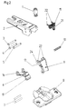
- 2 shows diagrammatically and pulled apart an inventive hinge
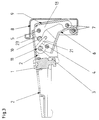
- 3 shows a longitudinal section through a hinge according to the invention in the closed position
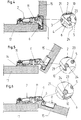
- 4 shows one Longitudinal section through a hinge according to the invention, a furniture side wall and a Furniture door, the furniture door being shown in the closed position
- 5 shows the same view as Fig. 4, with the furniture door shown in the half-open position is
- Fig. 6 shows the same view as Figs. 4 and 5 with the furniture door in the fully open position is shown.
- the hinge arm 2 is by means of a Base plate 14 attached to a furniture side wall 17, while the hinge cup 8 in a hole in a furniture door 15 is inserted.
- the hinge arm 2 and the Hinge cup 8 are via an inner articulated lever 6 and an outer one Articulated lever 9 connected to each other.
- the inner articulated lever 6 is articulated on the hinge arm 2 by means of an axis 4 and the outer articulated lever 9 by means of an axis 5.
- the hinge arm 2 is by means of a clamping screw 18 and one Joint adjustment screw 1 on the base plate 14, which is directly on the Furniture side wall 17 is attached, anchored.
- the closing mechanism of the hinge is formed by a leg spring 11, which is mounted on an axis 3 of the hinge arm 2.
- the outer articulated lever 9 is in the essentially executed with a U-profile and has two side webs 13.
- the inner articulated lever 6 is leaf-shaped and has a hinge cup side Roll 19 on, by means of which it on the U-bracket 7, i.e. the hinge cup side Hinge axis supports.
- the inner articulated lever 6 is provided with two wings 16 which are aligned perpendicular to the hinge axes 4, 5 and the holes or Have punch holes through which the hinge axis 4 of the hinge arm 2 projects, whereby the inner articulated lever 6 is mounted on the hinge arm 2.
- the leg spring 11 has two legs 21, 22. Furthermore, the leg spring 11 provided with two coils, each formed by two windings.
- the Rolls are formed by the leg 21 formed as a double web Leg spring 11 connected.
- the second leg 22 of the leg spring 11 is from formed two lateral spring ends of the leg spring 11 and is based on Center web of the hinge arm 2 designed with a U-profile.
- the leg 21 of the leg spring 11 designed as a double web presses on the outer articulated lever 9.
- the leg 21 of the leg spring 1 is located directly to a metal pin 10 which is between the two side webs 13 of the outer Articulated lever 9 is held.
- the outer articulated lever 9 is a double-armed lever formed with an arm 23 projecting freely into the hinge arm 2. This arm 23 is in the embodiment only from the side webs 13 of the outer Articulated lever 9 formed.
- the side webs 13 each have a recess 24 in which the Metal pin 10 is added.
- the metal pin 10 is preferably with the arm 23 or the side legs 13 of the outer articulated lever 9 welded or soldered.
- the metal pin 9 is made from a high-quality abrasion-resistant material, for example from a chrome-nickel layer or a chrome-vanadium alloy. Manganese steel can also be used Come into play.
- the surface of the metal pin 10 can coat the surface of the metal pin 10, for example with a titanium nitride coating, a titanium-carbon coating, a chrome nitride coating or a tungsten carbide coating. Furthermore can the surface of the metal pin 10 with solid lubrication, for example Molybdenum disulfide.
- the base plate 14 of the hinge is attached to the by means of screws or dowels Furniture side wall 17 attached and the hinge cup 8 has a flange that with Punch holes is provided through which screws, not shown, protrude, which hold the Improve hinge cup 8 in the furniture door 15.
Landscapes
- Engineering & Computer Science (AREA)
- Mechanical Engineering (AREA)
- Hinges (AREA)
- Closing And Opening Devices For Wings, And Checks For Wings (AREA)
- Pivots And Pivotal Connections (AREA)
- Vehicle Step Arrangements And Article Storage (AREA)
Abstract
Description
Claims (10)
- Scharnier mit einem Scharnierarm, der mittels eines äußeren und eines inneren Gelenkhebels, die zusammen mit vier Gelenkachsen ein Gelenkviereck bilden, mit einem Scharniertopf verbunden sind, wobei einer der Gelenkhebel als doppelarmiger Hebel mit einem frei in den Scharnierarm weisenden Arm ausgebildet ist, der von einer im Scharnierarm gelagerten Feder beaufschlagt wird und der zwei senkrecht zu den Gelenkachsen ausgerichtete Seitenstege aufweist, dadurch gekennzeichnet, daß die Feder auf einen vorzugsweise zylindrischen Metallstift (10) drückt, der zwischen den Seitenstegen (13) des frei in den Scharnierarm (2) ragenden Armes (23) des Gelenkhebels (9) gehalten ist.
- Scharnier nach Anspruch 1, dadurch gekennzeichnet, daß die Seitenstege (13) bzw. der Arm (23) an ihren freien Enden Aussparungen (24) aufweisen, in denen der Metallstift (10) gehalten ist.
- Scharnier nach Anspruch 1 oder 2, dadurch gekennzeichnet, daß der Metallstift (20) mit den Seitenstegen (13) bzw. dem Arm (23) verschweißt oder verlötet ist.
- Scharnier nach einem der Ansprüche 1 bis 3, dadurch gekennzeichnet, daß der Metallstift (10) gehärtet ist.
- Scharnier nach einem der Ansprüche 1 bis 4, dadurch gekennzeichnet, daß der Metallstift (10) zur Gänze oder teilweise aus einer Chrom-Nickel-Verbindung besteht.
- Scharnier nach einem der Ansprüche 1 bis 4, dadurch gekennzeichnet, daß der Metallstift (10) zur Gänze oder teilweise aus einer Chrom-Vanadium-Verbindung besteht.
- Scharnier nach einem der Ansprüche 1 bis 4, dadurch gekennzeichnet, daß der Metallstift (10) aus Manganstahl besteht.
- Scharnier nach einem der Ansprüche 1 bis 7, dadurch gekennzeichnet, daß die Oberfläche des Metallstiftes (10) mit einer Hartmetallbeschichtung, beispielsweise einer Titan-Nitrid-Beschichtung, versehen ist.
- Scharnier nach einem der Ansprüche 1 bis 7, dadurch gekennzeichnet, daß der Metallstift (10) mit einer Feststoffschmierung, beispielsweise aus Molybdändisulfid, versehen ist.
- Scharnier nach einem der Ansprüche 1 bis 9, dadurch gekennzeichnet, daß die Feder als Schenkelfeder (11) ausgeführt ist, die sich mit einem Schenkel (21) am Metallstift (10) und mit ihrem zweiten Schenkel (22) am Scharnierarm (2) abstützt.
Applications Claiming Priority (2)
| Application Number | Priority Date | Filing Date | Title |
|---|---|---|---|
| AT1764/97 | 1997-10-17 | ||
| AT176497 | 1997-10-17 |
Publications (2)
| Publication Number | Publication Date |
|---|---|
| EP0909864A2 true EP0909864A2 (de) | 1999-04-21 |
| EP0909864A3 EP0909864A3 (de) | 1999-05-06 |
Family
ID=3520510
Family Applications (1)
| Application Number | Title | Priority Date | Filing Date |
|---|---|---|---|
| EP98118681A Withdrawn EP0909864A3 (de) | 1997-10-17 | 1998-10-02 | Scharnier |
Country Status (4)
| Country | Link |
|---|---|
| EP (1) | EP0909864A3 (de) |
| JP (1) | JPH11217967A (de) |
| CN (1) | CN1215123A (de) |
| BR (1) | BR9804494A (de) |
Cited By (3)
| Publication number | Priority date | Publication date | Assignee | Title |
|---|---|---|---|---|
| EP2246509A1 (de) | 2009-04-28 | 2010-11-03 | Hawa Ag | Verschiebevorrichtung für drehbar gehaltene Trennelemente und Möbelstück |
| CN103306560B (zh) * | 2013-06-26 | 2016-05-18 | 伍志勇 | 家具用暗铰链 |
| EP4198233A1 (de) * | 2021-12-14 | 2023-06-21 | Julius Blum GmbH | Beschlag zur bewegbaren lagerung eines schwenkelementes |
Families Citing this family (7)
| Publication number | Priority date | Publication date | Assignee | Title |
|---|---|---|---|---|
| DE202004016396U1 (de) * | 2004-10-21 | 2005-01-05 | Julius Blum Gmbh | Dämpferanordnung |
| WO2013031810A1 (ja) | 2011-08-31 | 2013-03-07 | スガツネ工業株式会社 | 回転ダンパ及びダンパ付きヒンジ装置 |
| KR101544302B1 (ko) | 2011-08-31 | 2015-08-21 | 스가쓰네 고우교 가부시키가이샤 | 댐퍼가 형성된 힌지 장치 |
| WO2013031250A1 (ja) | 2011-08-31 | 2013-03-07 | スガツネ工業株式会社 | ヒンジ装置 |
| CN104100160A (zh) * | 2014-06-19 | 2014-10-15 | 常州市诺金精密机械有限公司 | 门窗安装用合页 |
| WO2019074101A1 (ja) * | 2017-10-13 | 2019-04-18 | キョーラク株式会社 | 容器、折り畳み容器 |
| CN107989497B (zh) * | 2017-11-10 | 2023-07-04 | 广东东泰五金精密制造有限公司 | 一种大盖位家具铰链 |
Citations (1)
| Publication number | Priority date | Publication date | Assignee | Title |
|---|---|---|---|---|
| AT392996B (de) | 1988-09-05 | 1991-07-25 | Blum Gmbh Julius | Scharnier |
Family Cites Families (4)
| Publication number | Priority date | Publication date | Assignee | Title |
|---|---|---|---|---|
| AT370839B (de) * | 1975-09-16 | 1983-05-10 | Lautenschlaeger Kg Karl | Schnappscharnier fuer moebeltueren |
| DE2700606C2 (de) * | 1977-01-08 | 1987-01-08 | Heinze, Richard, 4900 Herford | Möbelscharnier mit Schließ- und Zuhalteeinrichtung |
| DE2851774A1 (de) * | 1977-12-30 | 1980-06-12 | Hettich Hetal Werke | Moebelscharnier |
| DE19600063A1 (de) * | 1995-11-21 | 1997-05-28 | Scharwaechter Gmbh Co Kg | Kraftwagentürscharnier mit Brems- und Haltefunktion |
-
1998
- 1998-10-02 EP EP98118681A patent/EP0909864A3/de not_active Withdrawn
- 1998-10-07 JP JP10284863A patent/JPH11217967A/ja not_active Withdrawn
- 1998-10-15 BR BR9804494A patent/BR9804494A/pt not_active Application Discontinuation
- 1998-10-16 CN CN 98120967 patent/CN1215123A/zh active Pending
Patent Citations (1)
| Publication number | Priority date | Publication date | Assignee | Title |
|---|---|---|---|---|
| AT392996B (de) | 1988-09-05 | 1991-07-25 | Blum Gmbh Julius | Scharnier |
Cited By (6)
| Publication number | Priority date | Publication date | Assignee | Title |
|---|---|---|---|---|
| EP2246509A1 (de) | 2009-04-28 | 2010-11-03 | Hawa Ag | Verschiebevorrichtung für drehbar gehaltene Trennelemente und Möbelstück |
| EP2527576A1 (de) | 2009-04-28 | 2012-11-28 | Hawa Ag | Scharnier insbesondere für eine Verschiebevorrichtung |
| US8336972B2 (en) | 2009-04-28 | 2012-12-25 | Hawa Ag | Displacement device for pivotally held separation elements and article of furniture |
| CN103306560B (zh) * | 2013-06-26 | 2016-05-18 | 伍志勇 | 家具用暗铰链 |
| EP4198233A1 (de) * | 2021-12-14 | 2023-06-21 | Julius Blum GmbH | Beschlag zur bewegbaren lagerung eines schwenkelementes |
| WO2023110325A1 (de) * | 2021-12-14 | 2023-06-22 | Julius Blum Gmbh | Beschlag zur bewegbaren lagerung eines schwenkelementes |
Also Published As
| Publication number | Publication date |
|---|---|
| CN1215123A (zh) | 1999-04-28 |
| BR9804494A (pt) | 1999-11-09 |
| EP0909864A3 (de) | 1999-05-06 |
| JPH11217967A (ja) | 1999-08-10 |
Similar Documents
| Publication | Publication Date | Title |
|---|---|---|
| DE3914100C2 (de) | Kreuzgelenkscharnier mit Schließmechanismus | |
| DE10046750C1 (de) | Als Doppelantrieb ausgebildeter Möbelantrieb | |
| EP1830239B1 (de) | Rastmittel und Verwendung bei Betätigungshandhaben | |
| DE69324270T2 (de) | Toreinheit mit verstärktem gewichtsausgleich | |
| EP3094212B1 (de) | Schwenkgelenk und möbelstück mit einem solchen | |
| AT401667B (de) | Möbelscharnier mit schliessmechanismus | |
| EP0909864A2 (de) | Scharnier | |
| DE19608496A1 (de) | Drehstab-Türfeststeller für Kraftwagentüren | |
| EP1109983B1 (de) | Anschraubscharnier mit raststellung | |
| DE3829109C2 (de) | Elektrischer Schalter, insbesondere Lenkstockschalter für Kraftfahrzeuge | |
| EP2309086B1 (de) | Halteelement zum Verstellen eines Deckels eines Möbels | |
| DE2653106C2 (de) | Klappenhalter | |
| AT397275B (de) | Viergelenk-möbelscharnier mit einem türöffnungswinkel von mehr als 105 grad | |
| EP1070188A1 (de) | Kraftwagentürfeststeller | |
| EP0777025A1 (de) | Kraftwagentürscharnier mit Brems- und Haltefunktion | |
| DE19538824A1 (de) | Scharnieranordnung an einer Schwenkklappe, insbesondere einer Ganzglastür | |
| DE102008034070A1 (de) | Schließzylinder mit federkraftunterstützter Zylinderkernrückstellung | |
| EP2238305A1 (de) | Montageplatte | |
| AT408122B (de) | Scharnier | |
| AT3132U1 (de) | Scharnier | |
| AT404377B (de) | Türflügel-anschlagteil für möbelscharniere | |
| EP1223275B1 (de) | Band für Türen oder Fenster | |
| DE2554130A1 (de) | Moebelscharnier | |
| DE29909219U1 (de) | Teleskopierbares Staubsauger-Saugrohr | |
| DE202008014470U1 (de) | Frontverstellung für Schubkästen |
Legal Events
| Date | Code | Title | Description |
|---|---|---|---|
| PUAI | Public reference made under article 153(3) epc to a published international application that has entered the european phase |
Free format text: ORIGINAL CODE: 0009012 |
|
| PUAL | Search report despatched |
Free format text: ORIGINAL CODE: 0009013 |
|
| AK | Designated contracting states |
Kind code of ref document: A2 Designated state(s): AT BE CH CY DE DK ES FI FR GB GR IE IT LI LU MC NL PT SE |
|
| AX | Request for extension of the european patent |
Free format text: AL;LT;LV;MK;RO;SI |
|
| AK | Designated contracting states |
Kind code of ref document: A3 Designated state(s): AT BE CH CY DE DK ES FI FR GB GR IE IT LI LU MC NL PT SE |
|
| AX | Request for extension of the european patent |
Free format text: AL;LT;LV;MK;RO;SI |
|
| AKX | Designation fees paid | ||
| REG | Reference to a national code |
Ref country code: DE Ref legal event code: 8566 |
|
| STAA | Information on the status of an ep patent application or granted ep patent |
Free format text: STATUS: THE APPLICATION IS DEEMED TO BE WITHDRAWN |
|
| 18D | Application deemed to be withdrawn |
Effective date: 19991109 |