EP0909719B1 - Verschluss für Fläschchen - Google Patents
Verschluss für Fläschchen Download PDFInfo
- Publication number
- EP0909719B1 EP0909719B1 EP97117876A EP97117876A EP0909719B1 EP 0909719 B1 EP0909719 B1 EP 0909719B1 EP 97117876 A EP97117876 A EP 97117876A EP 97117876 A EP97117876 A EP 97117876A EP 0909719 B1 EP0909719 B1 EP 0909719B1
- Authority
- EP
- European Patent Office
- Prior art keywords
- protector
- posture
- seal
- stopping
- engaging
- Prior art date
- Legal status (The legal status is an assumption and is not a legal conclusion. Google has not performed a legal analysis and makes no representation as to the accuracy of the status listed.)
- Expired - Lifetime
Links
Images


Classifications
-
- B—PERFORMING OPERATIONS; TRANSPORTING
- B65—CONVEYING; PACKING; STORING; HANDLING THIN OR FILAMENTARY MATERIAL
- B65D—CONTAINERS FOR STORAGE OR TRANSPORT OF ARTICLES OR MATERIALS, e.g. BAGS, BARRELS, BOTTLES, BOXES, CANS, CARTONS, CRATES, DRUMS, JARS, TANKS, HOPPERS, FORWARDING CONTAINERS; ACCESSORIES, CLOSURES, OR FITTINGS THEREFOR; PACKAGING ELEMENTS; PACKAGES
- B65D51/00—Closures not otherwise provided for
- B65D51/002—Closures to be pierced by an extracting-device for the contents and fixed on the container by separate retaining means
Definitions
- This invention belongs to the technical field relating to vial containers according to the preamble of claims 1 or 3.
- Vial containers known so far have generally the following construction.
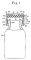
- a breaking portion 3 encompassed by easily breakable lines 2 such as scores is formed on the upper surface of a protector 1 made of an aluminum material
- an engagement protrusion 5 formed on the inner surface of a synthetic resin cover (hereinafter referred to as a flip-off cap) 4 is fixed to this breaking portion 3 by an eyelet structure
- a rubber stopper 6 having a vent slot 7 therein is fitted to a stopper portion 6a inside the protector 1
- a drug inside a vial bottle 8 is freeze-dried in such a posture that the rubber stopper 6 is fitted to a bottle mouth 8a of the vial bottle 8 in a lift state
- the rubber stopper 6 is fitted completely and air-tightly after freeze-drying
- the skirt portion of the protector 1 is thereafter wound and fastened by a winding machine.
- This vial container is used in the following way. As shown in Fig. 16, the breaking portion 3 is broken through the flip-off cap 4, the exposed upper portion of the rubber plug 6 is sterilized, a liquid such as distilled water is injected into the vial bottle 8 by piercing a needle such as a syringe so as to dissolve the freeze-dried drug, and the chemical solution is collected into the syringe for injection.
- a liquid such as distilled water
- a vial container in Japanese Patent Laid-Open No. 165252/1995.
- This vial container has the construction shown in Fig. 17.
- a synthetic resin protector 11 has an opening or a needle piercing window portion 12 closed by seal means 13 which can be easily pierced by a needle, on the top wall thereof, and vent means 17 communicating with the inside of a bottle container 20, inside a cylinder portion 11a thereof.
- a stopper 15 for sealing the gap between the inner surface of the top wall and the upper surface of a bottle mouth 20a is fitted into the protector 11, and engaging means 18 for keeping a semi-stopping freeze-drying posture of the protector 11 to correspond to the posture during transfer to freeze-drying means and a full-stopping seal posture of the protector 11 corresponding to the posture after freeze-drying, is disposed on the inner surface of the cylinder portion 11a constituting the protector 11.
- the object described above can be accomplished by insert-molding the seal means inside the protector.
- Reference numeral 51 denotes a protector made of a synthetic resin, and a needle piercing window portion 52 is formed at the center of the top wall of this protector 51.
- a seal 53 for closing the needle piercing window portion 52 is stuck to the upper surface of the top wall of the protector 51.
- Identification information (not shown) such as the name of the drug, the quantity of the drug, etc, is printed on the surface of this seal 53.
- a thin seal film through which a syringe needle can be easily pierced may be formed integrally at the needle piercing window portion 52 in place of the seal 53.
- a sheet-like packing 54 made of a rubber or a synthetic resin and coming into contact with the inner surface of the top wall is fitted to the inner upper part of the protector 51.
- the lower peripheral portion of the seal-like packing 54 is engaged with a small protrusion 55 formed integrally with the upper part of the inner surface of a cylinder portion 51 that constitutes the protector 51.
- the protrusion 55 may be omitted depending on the structure of the sheet-like packing 54.
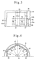
- Engaging plates 56 which are parallel to the protrusion 55 and have flexibility, are formed interruptedly and integrally at the substantial center of the inner surface of the cylinder portion 5 1a of the protector 51.
- the engaging plates 56 are constituted in the following way.
- Each engaging plate 56 comprises a lip structure which is inclined inward and upward towards the inside of the cylinder portion 51a, at the substantial center of the cylinder portion 51a constituting the protector 51 and moreover, is deformable in the outer direction and can be fitted into a gap portion 51b formed on the inner surface of the cylinder portion of the protector 51.
- the lower proximal portion of the engaging plate 56 is integral with the cylinder portion 51a of the protector 51.
- the engaging plates 56 are formed interruptedly as described above and more concretely, with suitable gaps between them as shown in Fig.
- Reference numeral 58 in the drawings denotes a draft hole of a mold used for molding the engaging plates 56. This draft hole 58 is closed by a seal 59.
- the needle piercing window portion 52 and the draft hole 58 are closed by the separate seals 53 and 59, respectively, but they can be closed by one common seal (not shown).
- the needle piercing window portion 52 of the protector 51 and the draft hole 58 can be closed without using the seals 53 and 59 by fitting tightly and separably a flip-off cap 4 shown in Fig.
- closing means is not particularly limited to the structure shown in the drawings.
- Protrusions 60 which are in parallel with the protrusion 55 and the engaging plates 56 described above are formed integrally at the lower part of the inner surface of the protector 51, and a flange portion 61b formed at the mouth portion 61b of a vial bottle 61 is clamped between the protrusions 60 and the proximal portions of the engaging plates 56 so that the protector 51 can be kept in the posture of semi-stopping freeze-drying as shown Fig. 1 and Fig. 7a. In this posture, freeze-drying can be effected because the inside of the vial bottle 61 is kept communicating with the external air through the vent passage 57 described above.
- the protrusions 60 may be omitted because the protector 51 can be kept in the stable semi-stopping freeze-drying posture by elongating the cylinder portion 51a of the protector 51, for example.
- Freeze-drying of the drug stored in the vial bottle 61 is effected in the semi-stopping posture shown in Fig. 1.
- the protector 51 is pushed down.
- the full-stopping seal posture shown in Fig. 2 is maintained and the inside of the vial bottle 61 is shut off from the external air by the function of the seal-like packing 54.
- the engaging plate 56 of the protector 51 which keeps contact with the flange portion 61b of the bottle mouth 61a is bent outward as shown in Fig.
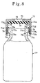
- Reference numeral 71 denotes a protector made of a synthetic resin.
- a needle piercing window portion 72 is formed at the center of the top wall of the protector 71 and a seal 73 for closing the needle piercing window portion 72 is stuck to the upper surface of the top wall of the protector 71.
- Identification information (not shown) such as the name of the drug, the quantity, etc, is printed on the surface of this seal 73.
- a thin seal film through which a syringe needle can pierce easily may be formed integrally with the needle piercing window portion 72.
- a sheet-like packing 74 made of a rubber or a synthetic resin material and coming into contact with the inner surface of the top wall is fitted to the inner upper part of the protector 71.
- this seal-like packing 74 is engaged with small protrusions 75 formed integrally at the upper part of the inner surface of a cylinder portion 71a constituting the protector 71.
- the protrusions 75 may be omitted depending on the structure of the sheet-like packing 74.
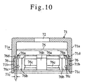
- An engagement recess 71b is formed round the entire periphery of the inner surface of the cylinder portion 71a of the protector 71.
- An annular member 76 to be fitted to the engagement recess 71b is formed separately from the protector 71. The thickness of this annular member 76 is greater than the depth of the engagement recess 71b.
- An engaging plate 76a the upper end of which is inclined upward and inward, which can bend and return to the original posture and the upper end of which engages with the lower side of the flange portion 77b formed at the bottle mouth 77a of the vial bottle 77 and keeps the full-stopping seal posture of the protector 71, is formed integrally at the inner upper portion of the annular member 76.
- Reference numeral 71c in the drawing denotes a restraining portion of the annular member 76.
- Vent grooves 76b having a depth t corresponding to the thickness of the annular members 76 and protruding from the engagement recess 71b of the protector 71 are formed in regularly annularly spaced positions of the annular member 76 in such a manner as to penetrate through the annular member 76 in the vertical direction, and the engaging plates 76a described above are formed between these vent grooves 76b.
- Reference numeral 76c in the drawing denotes an engaging protrusions which engage with the lower plate of the flange portion 77b of the bottle mouth and keep the semi-stopping freeze-drying posture at the time of this semi-stopping freeze-drying posture of the protector 71.
- a recess portion 71d shallower than the engagement recess 71b is so formed above the engagement recess 71b continuously formed on the protector 71.
- a flip-off cap 4 shown in Fig. 16 is fitted removably and tightly to the outer surface of the top wall of the protector 71 in place of the seal 73, and an engaging protrusion 5 having an eyelet structure and formed on the inner surface of the flip-off cap 4 is fitted appropriately into a needle piercing window portion 72 of the protector 71.
- the lower end of the engaging protrusion 5 is heat-treated so as to engage with the inner surface of the top wall of the protector 71. In this way, the tight fitting posture to the protector 71 can be maintained and the needle piercing window portion 72 of the protector 71 can be closed. Therefore, the closing means is not particularly limited to the structure shown in the drawing.
- the annular member 76 fitted to the engagement recess 71b of the protector 71 is prevented from coming off by the engagement recess 71b, more concretely, by the restraining portion 71c formed integrally with the lower side of the protector 71. Since the outside wall surface of the annular member 76 may be bonded to the inside wall surface of the engagement recess 71b by an adhesive or high frequency induction heating, however, the structure is not particularly limited to the structure shown in the drawings. This bonding means can omit the structure of the restraining portion 71c and assembly of the annular member 76 to the protector 71 can be simplified.
- Freeze-drying of the drug contained in the vial bottle is effected in the semi-stopping posture shown in Fig. 8.
- the protector 71 is pushed down.
- the full-stopping seal posture shown in Fig. 9 can be maintained and the inside of the vial bottle 77 is shut off from the external air by the function of the seal-like packing 74.
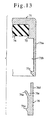
- the engaging plate 76a of the annular member 76 keeping contact with the bottle mouth flange portion 77b of the bottle mouth 77a shown in Figs. 12a, b and c is bent outward and enters the recess 71d as shown in Fig.
- the protector 71 is pushed and lowered smoothly by a relatively small force.
- the engaging plate 76a passes by the bottle mouth flange portion 77b, the engaging plate 76a is released as shown in Fig. 12c, returns to the inward inclination posture due to its flexibility, and the distal end of the engaging plate 76a engages with the lower jaw portion of the bottle mouth flange portion 77b.
- the outer periphery of the seal-like packing 74 undergoes strong compressive deformation between the upper surface of the bottle mouth 77a and the lower surface of the top wall constituting the protector 71 as can be clearly seen from Fig. 12c.
- a strong seal effect is produced, and the reaction of the compressed portion of the seal-like packing 74 pushes strongly the distal end of the engaging plate 76a to the jaw portion of the bottle mouth flange portion 77b.
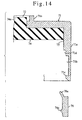
- An engagement recess 71b formed on the inner surface of a cylinder portion 71a of a protector is extended near to the lower side of a sheet-like packing 74.
- An annular sheet portion 76d having a length corresponding to the extension length of the engagement recess 71b is formed integrally at the upper end of the outside portion of the annular member 76.
- An insertion gap 76e which can be bent and can flexibly return to the original shape is formed between the engaging plate 76a and the inside wall surface of the annular sheet portion 76d.
- This embodiment (3) can obtain the same function as that of the embodiment (2) and because the engaging recess portion of the engagement plate 76a need not be formed in the protector 71, the mold for shaping the protector 71 can be simplified, and the quantity of the molding resin material can be saved, though it is limited.
- the sheet-like packing 74 is inserted when the protector 71 is molded.
- a round protrusion 71a is formed integrally at the center of the upper portion of the sheet-like packing 74 and while this round protrusion 74a is fitted to, and supported by, a female mold (not shown) for molding the protector 71, a male mold (not shown) is so disposed as to oppose the female mold.
- a resin material is then fed between both molds, and the protector 71 into which the sheet-like packing 74 is inserted is molded.
- the female mold is constituted in such a manner as to be capable of molding integrally a ring-like ridge 71e which is concentric with the round protrusion 74a, is somewhat taller than the round protrusion 74a and corresponds to the needle piercing window portion, on the upper surface of the protector 71 outside the round protrusion 74a fitted to, and supported by, the female mold.
- the needle piercing window portion 72 constituted by forming the ring-like ridge 71e can be closed by a seal (not shown).
- a protrusion or a low ridge 74b having a concentric ring-like structure is formed integrally on the lower surface of the sheet-like packing 74, and while this ridge 74b is fitted to, and supported by, the male mold (not shown) for molding the protector 71, the female mold (not shown) is so disposed as to oppose the male mold.
- the resin material is then fed between both molds, and the protector 71 into which the sheet-like packing 74 is inserted is molded.
- interposing means of the sheet-like packing 74 may be either of them and is not particularly limited.
Claims (5)
- Fläschchen, enthaltend eine Kunstharz-Schutzeinrichtung (51), die an der oberen Wand eines Fläschchens (61) mit einer Öffnung oder einem Nadeldurchstich-Fensterabschnitt (52), der von einer Versiegelungseinrichtung (53) verschlossen ist, die ohne weiteres von einer Nadel durchstochen werden kann, und an einem Zylinderabschnitt (51a) der Schutzeinrichtung (51) mit einer Belüftungseinrichtung ausgerüstet ist, die mit dem Inneren des Fläschchens (61) in Verbindung steht, welche Schutzeinrichtung (51) eine darin eingesetzte Dichtungseinrichtung zum Abdichten eines Spaltes zwischen einer inneren Oberfläche der oberen Wand und einer Flaschenöffnung (61a) hat,
dadurch gekennzeichnet, daß
eine Eingriffseinrichtung an der inneren Oberfläche des Zylinderabschnitts (51a) der Schutzeinrichtung (51) integriert angeordnet ist, um eine vollständig abdichtende Dichtungsstellung der Schutzeinrichtung (51) zu halten, wobei die Eingriffseinrichtung Eingriffsplatten (56) enthält, deren obere Enden nach innen und oben zu dem Zylinderabschnitt (51a) der Schutzeinrichtung hin geneigt sind und die flexibel, biegsam und verformbar sind, so daß eine Verschiebung aus einer halb abdichtenden Gefriertrocknungsstellung der Schutzeinrichtung (51), in der die Eingriffsplatten (56) mit der oberen Oberfläche der Flaschenöffnung (61a) in Eingriff stehen, in eine vollständig abdichtende Dichtungsstellung problemlos bewirkt werden kann, und die vollständig abdichtende Dichtungsstellung der Schutzeinrichtung (51), in der das obere Ende der Eingriffsplatten (56) in geneigter Stellung mit einer Vertiefung eines Flanschabschnitts (61b) der Flaschenöffnung (61a) in Eingriff steht, fest gesichert werden kann, und dadurch, daß die Eingriffsplatten (56) in geeigneten Spalten an der inneren Oberfläche des Zylinderabschnitts (51a), der die Schutzeinrichtung (51) bildet, angeordnet sind und die Belüftungseinrichtung zwischen den Eingriffsplatten (56) gebildet ist. - Fläschchen nach Anspruch 1,
dadurch gekennzeichnet, daß
eine Eingriffseinrichtung zum Verhindern des Anhebens der Schutzeinrichtung (51) und zum Halten der halb abdichtenden Gefriertrocknungsstellung an der inneren Oberfläche eines unteren Teils des Zylinderabschnitts (51a) angeordnet ist, der die Schutzeinrichtung (51) bildet. - Fläschchen, enthaltend eine Kunstharz-Schutzeinrichtung (71), die an der oberen Wand eines Fläschchens (77) mit einer Öffnung oder einem Nadeldurchstich-Fensterabschnitt (72), der von einer Versiegelungseinrichtung (73) verschlossen ist, die ohne weiteres von einer Nadel durchstochen werden kann, und an einem Zylinderabschnitt (71a) der Schutzeinrichtung (71). mit einer Belüftungseinrichtung ausgerüstet ist, die mit dem Inneren des Fläschchens (77) in Verbindung steht, welche Schutzeinrichtung (71) eine darin eingesetzte Dichtungseinrichtung zum Abdichten eines Spaltes zwischen einer inneren Oberfläche der oberen Wand und einer Flaschenöffnung (77a) sowie eine Eingriffseinrichtung hat, die an dem inneren oberen Abschnitt eines ringförmigen Elements (76) integriert angeordnet ist, um eine vollständig abdichtende Dichtungsstellung der Schutzeinrichtung (71) zu halten,
dadurch gekennzeichnet, daß
die Eingriffseinrichtung Eingriffsplatten (76a) umfasst, dere oberes Ende nach innen und oben geneigt ist, die flexibel, biegsam und verformbar sind, so daß sie ihre ursprüngliche Form wieder annehmen, und von welchen ein oberes Ende mit der unteren Seite eines Flanschabschnitts (77b) der Flaschenöffnung (77a) in Eingriff steht, um dadurch die vollständig abdichtende Dichtungsstellung der Schutzeinrichtung (71) zu halten, wobei das ringförmige Element (76), welches die Eingriffsplatten (76a) integral mit der Belüftungseinrichtung geformt hat, die mit dem Inneren des Fläschchens (77) in Verbindung steht, in eine Eingriffsvertiefung (71b) eingesetzt ist, die um den gesamten Umfang der inneren Oberfläche des Zylinderabschnitts (71a) der Schutzeinrichtung (71) gebildet ist. - Fläschchen nach Anspruch 3,
dadurch gekennzeichnet, daß
die Eingriffseinrichtungen zum Verhindern des Anhebens der Schutzeinrichtung (71) und Halten der halb abdichtenden Gefriertrocknungsstellung integral an der inneren Oberfläche an einem unteren Teil des ringförmigen Elements (76) gebildet sind. - Fläschchen nach Anspruch 3 oder 4,
dadurch gekennzeichnet, daß
die Dichtungseinrichtung (73) in das Innere der Schutzeinrichtung (71) eingespritzt ist.
Priority Applications (3)
| Application Number | Priority Date | Filing Date | Title |
|---|---|---|---|
| US08/950,770 US5992660A (en) | 1997-10-15 | 1997-10-15 | Closure for vial container |
| DE1997614258 DE69714258T2 (de) | 1997-10-15 | 1997-10-15 | Verschluss für Fläschchen |
| EP97117876A EP0909719B1 (de) | 1997-10-15 | 1997-10-15 | Verschluss für Fläschchen |
Applications Claiming Priority (2)
| Application Number | Priority Date | Filing Date | Title |
|---|---|---|---|
| US08/950,770 US5992660A (en) | 1997-10-15 | 1997-10-15 | Closure for vial container |
| EP97117876A EP0909719B1 (de) | 1997-10-15 | 1997-10-15 | Verschluss für Fläschchen |
Publications (2)
| Publication Number | Publication Date |
|---|---|
| EP0909719A1 EP0909719A1 (de) | 1999-04-21 |
| EP0909719B1 true EP0909719B1 (de) | 2002-07-24 |
Family
ID=26145833
Family Applications (1)
| Application Number | Title | Priority Date | Filing Date |
|---|---|---|---|
| EP97117876A Expired - Lifetime EP0909719B1 (de) | 1997-10-15 | 1997-10-15 | Verschluss für Fläschchen |
Country Status (2)
| Country | Link |
|---|---|
| US (1) | US5992660A (de) |
| EP (1) | EP0909719B1 (de) |
Families Citing this family (33)
| Publication number | Priority date | Publication date | Assignee | Title |
|---|---|---|---|---|
| US6786935B1 (en) * | 2000-03-10 | 2004-09-07 | Applied Materials, Inc. | Vacuum processing system for producing components |
| US6581939B1 (en) * | 2000-11-22 | 2003-06-24 | Emerson Power Transmission Manufacturing, L.P. | Bearing end cap with integrated seal |
| ES2187341B1 (es) * | 2001-02-28 | 2004-08-16 | Saint-Gobain Calmar S.A. | Capsula de un dispositivo para el cierre de una botella. |
| ES2337850T3 (es) | 2001-03-09 | 2010-04-29 | Gen-Probe Incorporated | Caperuza perforable. |
| US20030189023A1 (en) * | 2002-04-08 | 2003-10-09 | Fabricas Monterrey, S.A. De C.V. | Closure cap including film portion |
| US20050086830A1 (en) * | 2003-10-24 | 2005-04-28 | Zukor Kenneth S. | Processing cap assembly for isolating contents of a container |
| US6948631B2 (en) * | 2004-01-08 | 2005-09-27 | 3088081 Canada Inc. | Controllable tamper proof closure for a vial |
| US20060226113A1 (en) * | 2005-04-06 | 2006-10-12 | Clark Douglas P | Liquid vial closure with improved anti-evaporation features |
| US8387811B2 (en) | 2007-04-16 | 2013-03-05 | Bd Diagnostics | Pierceable cap having piercing extensions |
| US8387810B2 (en) | 2007-04-16 | 2013-03-05 | Becton, Dickinson And Company | Pierceable cap having piercing extensions for a sample container |
| DE102007058349A1 (de) * | 2007-06-29 | 2009-01-02 | Merck Patent Gmbh | Verschluss |
| CA2702004C (en) * | 2007-10-09 | 2015-11-24 | Gerard Laurent Buisson | Visual vacuum indicator |
| WO2009096851A1 (en) * | 2008-01-28 | 2009-08-06 | Milux Holding Sa | A drainage device comprising a filter cleaning device |
| FR2950035B1 (fr) | 2009-09-15 | 2011-09-02 | Raymond A & Cie | Coiffe de verrouillage pour recipient a col |
| FR2950865B1 (fr) | 2009-10-01 | 2011-10-28 | Raymond A & Cie | Coiffe de verrouillage pour recipient a col avec une capsule a pattes de fixation |
| FR2967655B1 (fr) * | 2010-11-24 | 2014-03-14 | Biocorp Rech Et Dev | Dispositif de bouchage d'un recipient, recipient equipe d'un tel dispositif et procede de fermeture d'un lot de tels recipients |
| US8544665B2 (en) | 2011-04-04 | 2013-10-01 | Genesis Packaging Technologies | Cap systems and methods for sealing pharmaceutical vials |
| FR2975675B1 (fr) * | 2011-05-23 | 2014-06-06 | Valois Sas | Organe de fixation et distributeur comprenant un tel organe. |
| FR2986782B1 (fr) | 2012-02-13 | 2014-03-07 | Raymond A & Cie | Dispositif de verrouillage de bouchon sur recipient a collerette, recipient a collerette obture par bouchon pourvu d'un tel dispositif de verrouillage |
| FR2987825B1 (fr) * | 2012-03-09 | 2015-06-05 | Biocorp Rech Et Dev | Dispositif de bouchage et recipient equipe d'un tel dispositif |
| DE102012112665B4 (de) * | 2012-12-19 | 2015-08-06 | Rudolf Lang | Abdeckung für Gefäße, insbesondere für Trinkgefäße |
| FR3001953B1 (fr) * | 2013-02-14 | 2016-01-01 | Transformation Des Elastomeres A Usages Medicaux Et Ind Soc D | Dispositif de fixation pour obturer un reservoir de produit fluide. |
| ITMI20132005A1 (it) * | 2013-12-02 | 2015-06-03 | Antonio Mutterle | Complesso di chiusura per flacone, relativo flacone e metodo di assemblaggio |
| JP6628152B2 (ja) * | 2014-06-18 | 2020-01-08 | アルテルゴン エス.エイ. | ボトルの密閉方法および関連する密閉されたボトル |
| US11781811B2 (en) | 2015-08-03 | 2023-10-10 | Gen-Probe Incorporated | Apparatus for maintaining a controlled environment |
| KR102408787B1 (ko) | 2015-08-03 | 2022-06-15 | 젠-프로브 인코포레이티드 | 제어된 환경을 유지하는 장치 |
| NL2015979B1 (en) * | 2015-12-17 | 2017-07-05 | Plasticum Netherlands B V | Packaging lid. |
| US10219983B2 (en) | 2016-08-03 | 2019-03-05 | Genesis Packaging Technologies | Cap systems with piercing member for pharmaceutical vials |
| US10266330B2 (en) * | 2017-02-14 | 2019-04-23 | Misumaru Sangyo Co., Ltd. | Compression bag and deflation valve for use therewith |
| US10920431B2 (en) * | 2017-12-26 | 2021-02-16 | David K. McNinch | Drain and vent cover |
| US11498725B1 (en) * | 2018-07-27 | 2022-11-15 | Elemental Scientific, Inc. | Fluoropolymer septum cap assembly |
| FR3098504B1 (fr) * | 2019-07-09 | 2021-06-04 | A Raymond Et Cie | coiffe de verrouillage pour récipient à col |
| WO2021202818A1 (en) * | 2020-03-31 | 2021-10-07 | Partsch George J | Universal capping system and the method of use thereof |
Family Cites Families (16)
| Publication number | Priority date | Publication date | Assignee | Title |
|---|---|---|---|---|
| US1316231A (en) * | 1919-09-16 | new yosk | ||
| CA639892A (en) * | 1962-04-17 | M. Ashkenaz David | Snap-on cartridge-needle unit | |
| US819235A (en) * | 1904-11-17 | 1906-05-01 | William A Lorenz | Hermetic closure for receptacles. |
| NL278403A (de) * | 1961-05-18 | |||
| US3715063A (en) * | 1970-03-18 | 1973-02-06 | Lion Fat Oil Co Ltd | Cap structure holding an inner closure |
| CA1119555A (en) * | 1978-10-20 | 1982-03-09 | Roman Andruchiw | Safety closure |
| ES266599Y (es) * | 1982-06-18 | 1983-11-16 | "dispositivo aplicable a la realizacion de analisis". | |
| FR2598137B1 (fr) * | 1986-05-05 | 1989-05-26 | Astraplastique Sa | Dispositif de bouchon a visser inviolable et son procede d'assemblage. |
| NZ222947A (en) * | 1986-12-19 | 1989-04-26 | Arlco Pty Ltd | Tamper-indicating tear tab cap for beer keg |
| DK158083C (da) * | 1988-01-11 | 1990-09-10 | Dansk Bakelit Ind As | Beskyttelseshaette til beholderudtoemningsventiler, navnlig anstikkerventiler paa fadoelfustager |
| DE3902672A1 (de) * | 1988-06-28 | 1990-02-08 | Wez Kunststoff | Verschlussanordnung fuer pharmazeutische flaschen |
| US5031787A (en) * | 1989-09-01 | 1991-07-16 | Anchor Hocking Packaging Company | Low height floating disk closure |
| US5269429A (en) * | 1990-05-15 | 1993-12-14 | Robert Finke Gmbh & Co. Kg | Closure cap for infusion or transfusion bottles |
| US5443853A (en) * | 1991-05-01 | 1995-08-22 | Anchor Hocking Packaging Co. | Press-on, pry-off closure for microwavable vacuum sealed container |
| US5314084A (en) * | 1992-08-21 | 1994-05-24 | The West Company, Incorporated | Two piece all plastic seal |
| JP2757117B2 (ja) * | 1993-10-21 | 1998-05-25 | 三共株式会社 | バイアル容器 |
-
1997
- 1997-10-15 US US08/950,770 patent/US5992660A/en not_active Expired - Lifetime
- 1997-10-15 EP EP97117876A patent/EP0909719B1/de not_active Expired - Lifetime
Also Published As
| Publication number | Publication date |
|---|---|
| EP0909719A1 (de) | 1999-04-21 |
| US5992660A (en) | 1999-11-30 |
Similar Documents
| Publication | Publication Date | Title |
|---|---|---|
| EP0909719B1 (de) | Verschluss für Fläschchen | |
| US4251003A (en) | Bottle closing device | |
| US8225949B2 (en) | Plug device for a container and container provided with one such device | |
| CN102259723B (zh) | 用于容器的封闭装置以及用于该装置的密封部件 | |
| EP0028411B1 (de) | Stopfen für Fläschchen | |
| US4253459A (en) | Additive transfer unit with stabilized sealing means | |
| JPH0680153A (ja) | 瓶に用いられる閉鎖装置 | |
| AU2004274263A1 (en) | Synthetic resin cap, closing device, and container-packed beverage | |
| AU6275494A (en) | Closure for medication container | |
| JP3780009B2 (ja) | 注射液瓶および輸液瓶のための無断開封防止キャップを備えた蓋 | |
| MXPA05001888A (es) | Sistema de cierre para un frasco, frasco, metodo de cerrado y llenado de un frasco y soporte para un frasco. | |
| CN218705357U (zh) | 用于药瓶的篡改易显塑胶封闭物 | |
| WO1991014633A1 (en) | Medicine vial cap for needleless syringe | |
| CN112208928B (zh) | 用于包括颈部的容器的锁定盖和容器 | |
| US4060911A (en) | Process for the preparation of a container closed under sterile conditions and containing lyophilized material | |
| JP3114059B2 (ja) | バイアル容器 | |
| US2561294A (en) | Closure for multiple dose vials | |
| JPH09286453A (ja) | バイアル容器 | |
| US3323276A (en) | Closures and methods for applying same | |
| US20240067412A1 (en) | Plastic closure device for a container for parenteral pharmaceutical products | |
| JPH0721564U (ja) | バイアルの密封閉鎖具 | |
| CN116888054A (zh) | 用于可肠胃外给药的药物的塑料封闭装置的橡胶密封元件 | |
| JPS6220217Y2 (de) | ||
| CA1117488A (en) | Additive transfer unit with stabilized sealing means | |
| IE41595B1 (en) | Process for the preperation of a closed container containing lyophilized material |
Legal Events
| Date | Code | Title | Description |
|---|---|---|---|
| PUAI | Public reference made under article 153(3) epc to a published international application that has entered the european phase |
Free format text: ORIGINAL CODE: 0009012 |
|
| AK | Designated contracting states |
Kind code of ref document: A1 Designated state(s): DE FR GB IT |
|
| 17P | Request for examination filed |
Effective date: 19990903 |
|
| AKX | Designation fees paid |
Free format text: DE FR GB IT |
|
| 17Q | First examination report despatched |
Effective date: 20000822 |
|
| GRAG | Despatch of communication of intention to grant |
Free format text: ORIGINAL CODE: EPIDOS AGRA |
|
| GRAG | Despatch of communication of intention to grant |
Free format text: ORIGINAL CODE: EPIDOS AGRA |
|
| GRAH | Despatch of communication of intention to grant a patent |
Free format text: ORIGINAL CODE: EPIDOS IGRA |
|
| GRAH | Despatch of communication of intention to grant a patent |
Free format text: ORIGINAL CODE: EPIDOS IGRA |
|
| GRAA | (expected) grant |
Free format text: ORIGINAL CODE: 0009210 |
|
| AK | Designated contracting states |
Kind code of ref document: B1 Designated state(s): DE FR GB IT |
|
| PG25 | Lapsed in a contracting state [announced via postgrant information from national office to epo] |
Ref country code: IT Free format text: LAPSE BECAUSE OF FAILURE TO SUBMIT A TRANSLATION OF THE DESCRIPTION OR TO PAY THE FEE WITHIN THE PRE;WARNING: LAPSES OF ITALIAN PATENTS WITH EFFECTIVE DATE BEFORE 2007 MAY HAVE OCCURRED AT ANY TIME BEFORE 2007. THE CORRECT EFFECTIVE DATE MAY BE DIFFERENT FROM THE ONE RECORDED.SCRIBED TIME-LIMIT Effective date: 20020724 Ref country code: FR Free format text: LAPSE BECAUSE OF FAILURE TO SUBMIT A TRANSLATION OF THE DESCRIPTION OR TO PAY THE FEE WITHIN THE PRESCRIBED TIME-LIMIT Effective date: 20020724 |
|
| REG | Reference to a national code |
Ref country code: GB Ref legal event code: FG4D |
|
| REF | Corresponds to: |
Ref document number: 69714258 Country of ref document: DE Date of ref document: 20020829 |
|
| EN | Fr: translation not filed | ||
| PLBE | No opposition filed within time limit |
Free format text: ORIGINAL CODE: 0009261 |
|
| STAA | Information on the status of an ep patent application or granted ep patent |
Free format text: STATUS: NO OPPOSITION FILED WITHIN TIME LIMIT |
|
| 26N | No opposition filed |
Effective date: 20030425 |
|
| PGFP | Annual fee paid to national office [announced via postgrant information from national office to epo] |
Ref country code: GB Payment date: 20061023 Year of fee payment: 10 |
|
| PGFP | Annual fee paid to national office [announced via postgrant information from national office to epo] |
Ref country code: DE Payment date: 20061229 Year of fee payment: 10 |
|
| GBPC | Gb: european patent ceased through non-payment of renewal fee |
Effective date: 20071015 |
|
| PG25 | Lapsed in a contracting state [announced via postgrant information from national office to epo] |
Ref country code: DE Free format text: LAPSE BECAUSE OF NON-PAYMENT OF DUE FEES Effective date: 20080501 |
|
| PG25 | Lapsed in a contracting state [announced via postgrant information from national office to epo] |
Ref country code: GB Free format text: LAPSE BECAUSE OF NON-PAYMENT OF DUE FEES Effective date: 20071015 |