EP0909404B1 - Optischer frequenzvervielfacher - Google Patents
Optischer frequenzvervielfacher Download PDFInfo
- Publication number
- EP0909404B1 EP0909404B1 EP97928381A EP97928381A EP0909404B1 EP 0909404 B1 EP0909404 B1 EP 0909404B1 EP 97928381 A EP97928381 A EP 97928381A EP 97928381 A EP97928381 A EP 97928381A EP 0909404 B1 EP0909404 B1 EP 0909404B1
- Authority
- EP
- European Patent Office
- Prior art keywords
- radiation
- beams
- harmonic
- output
- sample
- Prior art date
- Legal status (The legal status is an assumption and is not a legal conclusion. Google has not performed a legal analysis and makes no representation as to the accuracy of the status listed.)
- Expired - Lifetime
Links
- 230000003287 optical effect Effects 0.000 title claims description 32
- 230000005855 radiation Effects 0.000 claims description 153
- 239000013078 crystal Substances 0.000 claims description 69
- 239000000463 material Substances 0.000 claims description 27
- 230000002123 temporal effect Effects 0.000 claims description 8
- XBJJRSFLZVLCSE-UHFFFAOYSA-N barium(2+);diborate Chemical compound [Ba+2].[Ba+2].[Ba+2].[O-]B([O-])[O-].[O-]B([O-])[O-] XBJJRSFLZVLCSE-UHFFFAOYSA-N 0.000 claims description 6
- VCZFPTGOQQOZGI-UHFFFAOYSA-N lithium bis(oxoboranyloxy)borinate Chemical compound [Li+].[O-]B(OB=O)OB=O VCZFPTGOQQOZGI-UHFFFAOYSA-N 0.000 claims description 6
- 229910000402 monopotassium phosphate Inorganic materials 0.000 claims description 4
- 235000019796 monopotassium phosphate Nutrition 0.000 claims description 4
- PJNZPQUBCPKICU-UHFFFAOYSA-N phosphoric acid;potassium Chemical compound [K].OP(O)(O)=O PJNZPQUBCPKICU-UHFFFAOYSA-N 0.000 claims description 4
- DJHGAFSJWGLOIV-UHFFFAOYSA-M arsenate(1-) Chemical compound O[As](O)([O-])=O DJHGAFSJWGLOIV-UHFFFAOYSA-M 0.000 claims description 3
- 229910052792 caesium Inorganic materials 0.000 claims description 3
- TVFDJXOCXUVLDH-UHFFFAOYSA-N caesium atom Chemical compound [Cs] TVFDJXOCXUVLDH-UHFFFAOYSA-N 0.000 claims description 3
- WYOHGPUPVHHUGO-UHFFFAOYSA-K potassium;oxygen(2-);titanium(4+);phosphate Chemical compound [O-2].[K+].[Ti+4].[O-]P([O-])([O-])=O WYOHGPUPVHHUGO-UHFFFAOYSA-K 0.000 claims description 3
- 238000006243 chemical reaction Methods 0.000 description 30
- 238000005086 pumping Methods 0.000 description 8
- 238000000034 method Methods 0.000 description 5
- 238000010586 diagram Methods 0.000 description 4
- LFVGISIMTYGQHF-UHFFFAOYSA-N ammonium dihydrogen phosphate Chemical compound [NH4+].OP(O)([O-])=O LFVGISIMTYGQHF-UHFFFAOYSA-N 0.000 description 2
- 229910000387 ammonium dihydrogen phosphate Inorganic materials 0.000 description 2
- 239000007788 liquid Substances 0.000 description 2
- 235000019837 monoammonium phosphate Nutrition 0.000 description 2
- OFBQJSOFQDEBGM-UHFFFAOYSA-N Pentane Chemical compound CCCCC OFBQJSOFQDEBGM-UHFFFAOYSA-N 0.000 description 1
- 230000004075 alteration Effects 0.000 description 1
- 230000003321 amplification Effects 0.000 description 1
- 230000015556 catabolic process Effects 0.000 description 1
- 230000001627 detrimental effect Effects 0.000 description 1
- 230000003467 diminishing effect Effects 0.000 description 1
- 230000000694 effects Effects 0.000 description 1
- VLKZOEOYAKHREP-UHFFFAOYSA-N hexane Substances CCCCCC VLKZOEOYAKHREP-UHFFFAOYSA-N 0.000 description 1
- 238000003384 imaging method Methods 0.000 description 1
- 238000002347 injection Methods 0.000 description 1
- 239000007924 injection Substances 0.000 description 1
- 230000001678 irradiating effect Effects 0.000 description 1
- 238000003199 nucleic acid amplification method Methods 0.000 description 1
- 239000000243 solution Substances 0.000 description 1
Images


Classifications
-
- H—ELECTRICITY
- H01—ELECTRIC ELEMENTS
- H01S—DEVICES USING THE PROCESS OF LIGHT AMPLIFICATION BY STIMULATED EMISSION OF RADIATION [LASER] TO AMPLIFY OR GENERATE LIGHT; DEVICES USING STIMULATED EMISSION OF ELECTROMAGNETIC RADIATION IN WAVE RANGES OTHER THAN OPTICAL
- H01S3/00—Lasers, i.e. devices using stimulated emission of electromagnetic radiation in the infrared, visible or ultraviolet wave range
- H01S3/09—Processes or apparatus for excitation, e.g. pumping
- H01S3/091—Processes or apparatus for excitation, e.g. pumping using optical pumping
- H01S3/094—Processes or apparatus for excitation, e.g. pumping using optical pumping by coherent light
- H01S3/094034—Processes or apparatus for excitation, e.g. pumping using optical pumping by coherent light the pumped medium being a dye
-
- G—PHYSICS
- G02—OPTICS
- G02F—OPTICAL DEVICES OR ARRANGEMENTS FOR THE CONTROL OF LIGHT BY MODIFICATION OF THE OPTICAL PROPERTIES OF THE MEDIA OF THE ELEMENTS INVOLVED THEREIN; NON-LINEAR OPTICS; FREQUENCY-CHANGING OF LIGHT; OPTICAL LOGIC ELEMENTS; OPTICAL ANALOGUE/DIGITAL CONVERTERS
- G02F1/00—Devices or arrangements for the control of the intensity, colour, phase, polarisation or direction of light arriving from an independent light source, e.g. switching, gating or modulating; Non-linear optics
- G02F1/35—Non-linear optics
- G02F1/37—Non-linear optics for second-harmonic generation
-
- G—PHYSICS
- G02—OPTICS
- G02F—OPTICAL DEVICES OR ARRANGEMENTS FOR THE CONTROL OF LIGHT BY MODIFICATION OF THE OPTICAL PROPERTIES OF THE MEDIA OF THE ELEMENTS INVOLVED THEREIN; NON-LINEAR OPTICS; FREQUENCY-CHANGING OF LIGHT; OPTICAL LOGIC ELEMENTS; OPTICAL ANALOGUE/DIGITAL CONVERTERS
- G02F1/00—Devices or arrangements for the control of the intensity, colour, phase, polarisation or direction of light arriving from an independent light source, e.g. switching, gating or modulating; Non-linear optics
- G02F1/35—Non-linear optics
- G02F1/353—Frequency conversion, i.e. wherein a light beam is generated with frequency components different from those of the incident light beams
- G02F1/354—Third or higher harmonic generation
Definitions
- the invention relates to an harmonic generator system for efficiently generating higher order harmonic radiation from an input beam of fundamental frequency radiation.
- the system may be used to generate beams of second, third or fourth harmonic radiation.
- the system is particularly suitable for use with lasers which are used to pump a secondary laser system as multiple output beams may be generated, each being used to drive separate stages of the laser system.
- the generation of second harmonic frequencies. 2 ⁇ may be achieved by irradiating an appropriate crystal with a beam of primary radiation of frequency ⁇ . Some fraction of the incident energy is converted into the second harmonic within the crystal.
- crystals which may be used for the generation of second harmonic frequencies are potassium dihydrogen phosphate (KDP) and ammonium dihydrogen phosphate (ADP).
- Second harmonics of a primary laser beam are often used to pump a secondary laser system, for example a dye laser. It is common in most secondary lasers of this type to sub-divide the pumping beam (the second harmonic) into a series of lower energy beams, graded in intensity, which are then used to pump the various stages of the secondary laser system such as the oscillators and the amplifiers.
- the efficiency of the second harmonic generation process depends on the crystal material used and the power of the incident primary radiation. Typically, the efficiency with which second harmonics can be generated using a conventional frequency doubling crystal is only 50% to 60% of the primary laser source.
- the second harmonic may be separated using a prism arrangement or a dichoric mirror and the remaining fraction of fundamental radiation is wasted. Because of the limitation of the efficiency with which higher frequencies can be produced, powerful and bulky lasers may be needed in order to achieve sufficiently energetic second harmonic frequency beams for pumping applications.
- the present invention relates to a system for generating a plurality of beams of multiple order harmonic radiation from an input beam of fundamental frequency radiation with a conversion efficiency approaching 100%.
- the system may be used to generate a plurality of beams of second, third or fourth harmonic radiation.
- the system is particularly suitable for use with lasers which are used as pump sources for a secondary laser system as the output beams are conveniently split into separate beams which may be used to pump the separate stages of the secondary laser system.
- the system therefore enables a smaller and more convenient primary laser to be used to achieve sufficiently energetic beams of multiple order harmonic radiation than can be achieved using known techniques.
- a system for generating at least two output beams of higher order harmonic radiation from an input beam of fundamental radiation comprises;
- the first and further samples are arranged in series such that the beams of fundamental radiation output from each of the first and further samples pass through the next sample in the series, such that at least two output beams of second harmonic radiation may be generated.
- the system comprises a first sample of non linear optical material and two further samples of non linear optical material, such that three output beams of second harmonic radiation may be generated.
- the system may also comprise means for supplying the input beam of fundamental radiation,
- the input beam of fundamental radiation may be supplied by a laser.
- system may also include a sub-system for deriving the input beam of radiation from a beam of primary radiation of frequency ⁇ , wherein said sub-system comprises;
- the system preferably comprises a first sample of non linear optical material and two further samples of non linear optical material such that three output beams of fourth harmonic radiation may be generated.
- the system may also comprise means for supplying primary radiation to the sub-system, for example a laser.
- the means for increasing the intensity of radiation incident on any of the first or further samples may be a refracting telescope, a system of reflecting telescopes or a system of anamorphic prisms.
- the means for increasing the intensity of radiation incident on any of the first or further samples may have a variable magnification such that the relative intensities of the output beams of higher order harmonic radiation generated by the system may be varied by varying the magnification.
- the means for separating fundamental radiation and higher harmonic radiation output from any of the first or further samples may be chromatic separators, for example dichroic mirrors, prisms or polarisers.
- system may also include a sub-system for deriving the input beam of radiation from a beam of primary radiation of frequency ⁇ , wherein said sub-system comprises;
- the system preferably comprises a first sample of non linear optical material two further samples of non linear optical material, such that three output beams of third harmonic radiation may be generated.
- the system may also comprise means for providing primary radiation, for example a laser.
- the additional, first or further samples of non linear optical material may be non linear optical crystals.
- KTP potassium titanyl phosphate
- KDP potassium dihydrogen phosphate
- KD*P deuterated KDP
- CDA caesium dihydrogen arsenate
- CDA deuterated CDA
- BBO beta barium borate
- LBO lithium triborate
- the output beams of higher order harmonic radiation may be used to drive separate stages of a secondary laser system.
- the beams may be combined coherently to form a single output beam.
- the means for coherently combining the output beams of higher harmonic radiation may comprise a stimulated Brillouin scattering (SBS) cell and at least one Brillouin amplifier.
- SBS stimulated Brillouin scattering
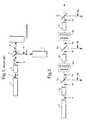
- an incident beam of radiation 1, with frequency ⁇ is emitted from a primary laser 2 and is passed through a frequency doubling crystal 3.
- the radiation 4 exiting the crystal 3 therefore comprises components of radiation with frequencies of ⁇ and 2 ⁇ .
- the frequencies may then be separated by means of a dichroic separator 5, for example a dichroic mirror, or any other chromatic separator, such as a prism.
- the second harmonic beam 6 may then be used to pump a secondary laser 7.
- the conversion efficiency of this system would typically be 50% to 60%.
- An improved second harmonic efficiency may be achieved by using the system shown in Figure 2.
- the primary laser 2 emits a beam of fundamental radiation 1 with frequency ⁇ .
- the radiation 1 is then passed through a series of frequency doubling crystals 3a,3b,3c, dichroic mirrors 5a,5b,5c and telescopes 9a,9b.
- the crystals may be any non linear optical crystal capable of generating second harmonic frequencies of incident fundamental frequency radiation.
- suitable chi(2) materials which may be used are potassium titanyl phosphate (KTP), potassium dihydrogen phosphate (KDP), deuterated KDP (KD*P), caesium dihydrogen arsenate (CDA), deuterated CDA (CD*A), beta barium borate (BBO) and lithium triborate (LBO).
- KTP potassium titanyl phosphate
- KDP potassium dihydrogen phosphate
- KD*P deuterated KDP
- CDA caesium dihydrogen arsenate
- CDA deuterated CDA
- BBO beta barium borate
- LBO lithium triborate
- the crystals used may all be of the same material or various different crystals may be used. Typically the crystals have a pathlength of 10 mm.
- the primary radiation of frequency ⁇ gives rise to radiation having second harmonic frequency components.
- the beam of radiation 4a transmitted by the crystal 3a therefore contains frequency components ⁇ and 2 ⁇ .
- the dichroic mirror 5a separates the frequencies so that the fundamental frequency beam 8a is passed to a refracting telescope 9a while the frequency doubled beam 6a may be passed to a secondary laser system (not shown) for pumping purposes.
- a polariser or a prism may be used instead of the dichroic mirror 5a to separate the beams of fundamental and second harmonic frequency radiation.
- the diameter of the fundamental frequency beam 8a is reduced so that the intensity is high enough on entering the second crystal 3b to allow efficient conversion.
- the demagnifying power of the telescope is usually chosen to restore the peak intensity to a similar level as the primary fundamental frequency beam 1.
- the relative intensity of second harmonic radiation generated at each crystal stage may be varied.
- a telescope may also be mounted in front of the first crystal 3a to increase the intensity of fundamental frequency radiation entering the first crystal, although this is not essential.
- the fundamental frequency beam 8a gives rise to the generation of second harmonic frequencies.
- a dichroic mirror 5b may be used to separate the fundamental frequency beam 8b and the frequency doubled beam 6b.
- the frequency doubled beam 6b may then be used to pump a secondary laser (not shown) while the fundamental frequency beam 8b is passed through a third crystal 3c and the process is repeated.
- the conversion efficiency obtained using the system shown in Figure 2 depends on the particular crystals used, the number of crystal stages in the system and the telescope demagnifications.
- a second harmonic conversion efficiency of greater than 97% may be achieved.
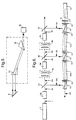
- Additional crystals, telescopes and dichroic mirrors may be included to increase the efficiency further, with diminishing return as the residual fundamental energy is used up. However, since the residual fundamental energy is telescoped down at each crystal, the required crystal size becomes increasingly smaller at each stage.
- the multiple beams generated using the second harmonic generator system shown in Figure 2 are particularly useful for pumping secondary lasers and similar devices as the total harmonic radiation is conveniently separated into beams of graded energy.
- the last second harmonic beam generated 6c will be the weakest and is therefore ideally suited to pump a laser oscillator or an optical parametric oscillator.
- the penultimate beam 6b will be of higher energy and may therefore be used to drive a laser preamplifier or optical parametric preamplifier.
- the first second harmonic beam 6a generated has the greatest energy and is therefore ideally suited for pumping a power amplifier stage.
- Figure 3 shows the theoretical three stage spatial profiles of generated second harmonic beams for input beams of 60MW/cm 2 ( Figure 3(a)) and 90MW/cm 2 ( Figures 3(b)).
- Figure 4 shows the three stage temporal profiles of generated second harmonic beams for input beams of 60MW/cm 2 ( Figure 4(a)) and 90MW/cm 2 ( Figures 4(b)).
- a useful feature of the system is that the duration of the second harmonic pulses that are generated 6a.6b,6c progressively lengthen and the spatial profiles of the pulses can be made more flat-topped with each successive crystal stage. This is due to the effects of pump depletion.
- This feature makes the system particularly suitable to provide a pump source for optical parametric oscillators and other laser systems as the flat topped spatial profile can reduce the risk of damage and the corresponding longer pumping pulse can help to provide a better temporal overlap between the oscillator output pulse and the subsequent amplifier pump pulses.
- the conversion efficiency associated with each successive stage also becomes progressively higher due to the flattening of the temporal and spatial profiles.
- the theoretical conversion efficiencies for three crystal stages (in sequential order) for an initial Gaussian 60 MW/cm 2 peak input intensity are 52%, 75% and 81%, giving a total conversion of nearly 98%.
- the increased conversion efficiencies at the second and third stages are due to the flattening of the spatial profile.
- Relay imaging between the crystal stages could be used to allow near field conversion at any demagnification but vacuum telescopes would be needed to avoid air breakdown at the intermediate foci. Less bulky Galilean telescopes are a more practical solution for moderate demagnifications.
- the crystals 3a,3b,3c may be mounted such that the angle at which incident radiation enters each one may be varied. By varying this angle the amount of second harmonic radiation generated at each stage (6a,6b,6c) may be varied, although in most cases the maximum possible output is likely to be required.
- a system of anamorphic prisms 10 may be used instead of the refracting telescopes 9a,9b (see Figure 2) in order to increase the intensity of radiation incident on each of the crystals 3a,3b,3c.
- a system of reflecting telescopes may be used or a system axis parabolic mirrors.
- the second harmonic beams 6a, 6b, 6c may also be coherently combined to form a single output 11.
- a stimulated Briliouin scattering (SBS) cell 15 imparts a small frequency downshift to the second harmonic signal 6c and generates an output signal 17.
- the frequency downshift is equivalent to the acoustic frequency characteristic of the Brillouin material.
- Suitable materials for use in the SBS cell would be liquid N-hexane, liquid N-pentane or gaseous C 2 F 6 .
- the second harmonic signal 6c is used as the input signal to a Brillouin amplifier 12a and one of the other second harmonic signals 6b is used to pump this amplifier.
- the amplified output from this Brillouin amplifier 12a becomes the signal for a second Brillouin amplifier 12b, and so forth depending on the number of second harmonic outputs from the system.
- Polarisers 13 and quarter wave plates 14 are used to direct the pump beams into the Brillouin amplifiers and to convert linearly polarised radiation into circularly polarised radiation with the polarisers 13 and quarter wave plates 14 arranged such that beams 6a and 6b do not reach the SBS cell 15. As the signal 17 proceeds through the Brillouin amplifiers, energy in beams 6a and 6b is imparted to 6c, resulting in a single combined output beam 11.
- amplification can proceed in either direction, starting with either the weakest or the strongest beam, but since the SBS cell efficiency is never 100% efficient it is preferable to derive the amplifier signal from the weakest beam (i.e. 6c) within the threshold limitations of the SBS cell.
- Mode matching optics for example telescopes (not shown), are also included between the Brillouin amplifiers 12a, 12b as the various beams are of different initial diameters, and to reach the required gIL value (Brillouin gain) for the efficient operation of the Brillouin amplifiers.
- Optical delay lines are also included in beams 6a,6b,6c to ensure proper temporal overlap of the various beams in the Brillouin amplifiers 12a,12b.
- the principle behind the system may also be used to generate multiple beams of radiation with four times the frequency of the fundamental radiation, 4 ⁇ (fourth harmonic generation).
- an additional frequency doubling crystal 18 is used and the output beam 4a from this crystal will have fundamental and second harmonic frequency components which may then be separated by a chromatic separator 5a.
- the crystals for use in this system may be any of one the examples mentioned previously.
- the separated second harmonic beam 6a then becomes the input beam to a three crystal system shown in Figure 2 (i.e. the beam input to the first of the three crystals has frequency 2 ⁇ ), with the addition of a third telescope 19 mounted in front of the first of the three crystals 3a.
- the system therefore generates three output beams 20a,20b,20c of four times the frequency of the fundamental beam (and two times the frequency of beam 6a).
- the fourth harmonic output beams 20a,20b.20c may be used separately to drive individual stages of an amplifier system or may be combined coherently to form a single output.
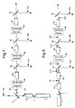
- the principle behind the system may be used to generate multiple beams of radiation with three times the frequency of the fundamental radiation from the laser source (third harmonic generation).
- Fundamental frequency radiation 1 from the laser 2 enters a first second harmonic crystal 3a. This crystal is chosen and adjusted so that approximately 67% conversion efficiency into the second harmonic is achieved. At this conversion efficiency, the fundamental harmonic photons and the second harmonic photons are matched in numbers.
- the conversion process for generating third harmonic radiation involves adding together one photon having fundamental frequency, ⁇ , to one photon having second harmonic frequency, 2 ⁇ , therefore generating a photon with third harmonic frequency, 3 ⁇ , which is equal in energy to the sum of the first and second harmonic photons.
- the radiation 4a output from the first crystal 3a is then passed through a second crystal 3b so as to generate third harmonic radiation. Assuming that the conversion efficiency is less than 100%, radiation 21a emerging from the second crystal 3b will contain radiation having frequency components ⁇ , 2 ⁇ and 3 ⁇ .
- a first dichroic separator 5a is then used to split off the third harmonic radiation 22a.
- the residual radiation beam 23a containing fundamental and second harmonic frequency components is passed through a telescope 9a to reduce the beam size. This increases the intensity of radiation 23a and ensures that the conversion efficiency is high when the radiation passes through the subsequent crystal in the chain, crystal 3c.
- a second dichroic separator 5b separates third harmonic radiation 22b generated in the crystal 3c and residual radiation 23b (having frequency components ⁇ and 2 ⁇ ), residual radiation is passed through a second telescope 9b and enters a third crystal 3d, generating a third output beam of third harmonic radiation 22c.
- the crystals for use in the system of Figure 8 may be any of one the examples mentioned previously.
- the beam transmitted by each of the dichroic separators 5a,5b,5c contain two frequency components, ⁇ and 2 ⁇ , and it is important that these two wavelengths remain together in a single beam prior to entering the next telescope in the sequence.
- the dichroic separators and the telescopes must therefore be free from chromatic aberrations and prisms may not be used in this particular embodiment of the invention.
- Polarisers could be used.
- the telescopes 9a,9b,9c must be achromatic and cannot be replaced by anamorphic prisms (as described previously for second and fourth harmonic generation systems).
- Mirror telescopes would be suitable for use in the third harmonic generation system.
Landscapes
- Physics & Mathematics (AREA)
- Nonlinear Science (AREA)
- Electromagnetism (AREA)
- Optics & Photonics (AREA)
- Engineering & Computer Science (AREA)
- Plasma & Fusion (AREA)
- General Physics & Mathematics (AREA)
- Lasers (AREA)
- Optical Modulation, Optical Deflection, Nonlinear Optics, Optical Demodulation, Optical Logic Elements (AREA)
Claims (22)
- System zum Erzeugen eines Ausgangsstrahls (11) einer Oberwellenstrahlung höherer Ordnung aus einem Eingangsstrahl (1; 6a; 4a) einer Grundstrahlung, das umfaßt:dadurch gekennzeichnet, daß die Vorrichtung ferner eine stimulierte Brillouin-Streuzelle (SBS-Zelle) (15) und wenigstens einen Brillouin-Verstärker (12a, 12b) umfaßt, die die Ausgangsstrahlen (6b, 6c; 20a, 20b; 22a, 22b) der Oberwellenstrahlung höherer Ordnung kohärent kombinieren.eine erste Probe (3a; 3a; 3b) eines nichtlinearen optischen Materials zum Empfangen des Eingangsstrahls und zum Erzeugen von Ausgangsstrahlung (4a; 3a; 21a), die Strahlen der Grundstrahlung und der Oberwellenstrahlung höherer Ordnung (6a; 20a; 22a) umfaßt,ein Mittel (5a) zum Trennen der Strahlen der Grundstrahlung und der Oberwellenstrahlung höherer Ordnung, die von der ersten Probe ausgegeben werden,wenigstens eine weitere Probe eines nichtlinearen optischen Materials (3b, 3c; 3b, 3c; 3c, 3d), wobei die erste und die weiteren Proben in Serie angeordnet sind, wobei jede weitere Probe ein zugeordnetes Mittel (9a, 9b) zum Erhöhen der Intensität der auf die weitere Probe einfallenden Strahlung und ein Mittel (5b, 5c) zum Trennen der Strahlen der Grundstrahlung und der Oberwellenstrahlung höherer Ordnung, die von der weiteren Probe ausgegeben werden, aufweist, und wobei ausgewählte Strahlen der Strahlung, die von jeweils der ersten und den weiteren Proben ausgegeben werden, durch die nachfolgende Probe in der Serie laufen und weitere Strahlen der Grundstrahlung und der Oberwellenstrahlung höherer Ordnung (6b, 6c; 20a, 20b; 22a, 22b) erzeugen,
- System nach Anspruch 1, bei dem die erste und die weiteren Proben (3a, 3b) wenigstens zwei Ausgangsstrahlen der Oberwellenstrahlung zweiter Ordnung (6a, 6b) erzeugen, wobei die zwei oder mehr Ausgangsstrahlen der Oberwellenstrahlung zweiter Ordnung mittels der stimulierten Brillouin-Streuzelle (SBS-Zelle) (15) und des einen oder der mehreren Brillouin-Verstärker (12a, 12b) kohärent kombiniert werden.
- System nach Anspruch 2, das eine erste Probe eines nichtlinearen optischen Materials (3a) und zwei weitere Proben eines nichtlinearen optischen Materials (3b, 3c) umfaßt, um drei Ausgangsstrahlen einer Oberwellenstrahlung zweiter Ordnung (6a, 6b, 6c) zu erzeugen, wobei die drei Ausgangsstrahlen der Oberwellenstrahlung zweiter Ordnung mittels der stimulierten Brillouin-Streuzelle (SBS-Zelle) (15) und des einen oder der mehreren Brillouin-Verstärker (12a, 12b) kohärent kombiniert werden.
- System nach irgendeinem der Ansprüche 1 bis 3, das ferner ein Mittel (2) zum Zuführen des Eingangsstrahls der Grundstrahlung umfaßt.
- System nach Anspruch 4, bei dem das Mittel (2) zum Zuführen des Eingangsstrahls der Grundstrahlung ein Laser ist.
- System nach Anspruch 1, das ferner ein Untersystem zum Ableiten eines Eingangsstrahls der Strahlung (6a) aus einem Strahl der Primärstrahlung (1) mit der Frequenz ω enthält, wobei das Untersystem umfaßt:wobei der Strahl der Oberwellenstrahlung zweiter Ordnung (6a), der vom Untersystem ausgegeben wird, in das System eingegeben wird, so daß das System verwendet werden kann, um wenigstens zwei Ausgangsstrahlen einer Oberwellenstrahlung vierter Ordnung (20a, 20b, 20c) zu erzeugen, wobei die zwei oder mehr Ausgangsstrahlen der Oberwellenstrahlung vierter Ordnung mittels der stimulierten Brillouin-Streuzelle (SBS-Zelle) (15) und des einen oder der mehreren Brillouin-Verstärker (12a, 12b) kohärent kombiniert werden.eine zusätzliche Probe eines nichtlinearen optischen Materials (18) zum Empfangen des Strahls der Primärstrahlung (1) und zum Erzeugen der Ausgangsstrahlung (4a), die die Primärstrahlung (8a) ω und die Oberwellenstrahlung zweiter Ordnung (6a) 2ω umfaßt,ein Mittel (5) zum Trennen der Strahlen der von der zusätzlichen Probe ausgegebenen Primärstrahlung und Oberwellenstrahlung zweiter Ordnung, undein Mittel (19) zum Erhöhen der Intensität der auf die erste Probe (3a) einfallenden Strahlung,
- System nach. Anspruch 6, das eine erste Probe eines nichtlinearen optischen Materials (3a) und zwei weitere Proben eines nichtlinearen optischen Materials (3b, 3c) umfaßt, so daß drei Ausgangsstrahlen einer Oberwellenstrahlung vierter Ordnung (20a, 20b, 20c) erzeugt werden können, wobei die zwei oder mehr Ausgangsstrahlen der Oberwellenstrahlung vierter Ordnung mittels der stimulierten Brillouin-Streuzelle (SBS-Zelle) (15) und des einen oder der mehreren Brillouin-Verstärker (12a, 12b) kohärent kombiniert werden.
- System nach Anspruch 7, das ferner ein Mittel (2) zum Zuführen der Primärstrahlung zum Untersystem umfaßt.
- System nach Anspruch 8, bei dem das Mittel (2) zum Zuführen der Primärstrahlung zum Untersystem ein Laser ist.
- System nach Anspruch 1 oder 6, bei dem das Mittel (9a, 9b; 19, 9a, 9b) zum Erhöhen der Intensität der auf irgendeine der ersten oder weiteren Proben einfallenden Strahlung ein Brechungsteleskop ist.
- System nach Anspruch 1 oder 6, bei dem das Mittel (9a, 9b; 19, 9a, 9b) zum Erhöhen der Intensität der auf irgendeine der ersten oder weiteren Proben einfallenden Strahlung ein System von Reflexionsteleskopen ist.
- System nach Anspruch 1 oder 6, bei dem das Mittel (9a, 9b; 19, 9a, 9b) zum Erhöhen der Intensität der auf irgendeine der ersten, zusätzlichen oder weiteren Proben einfallenden Strahlung ein System von anamorphotischen Prismen ist.
- System nach Anspruch 1 oder 6, bei dem die Mittel (5a, 5b, 5c; 5, 5a, 5b, 5c) zum Trennen der Grundstrahlung und der Oberwellenstrahlung höherer Ordnung, die von irgendeiner der ersten, zusätzlichen oder weiteren Proben (3a, 3b, 3c; 18, 3a, 3b, 3c) ausgegeben werden, chromatische Separatoren sind.
- System nach Anspruch 13, bei dem die chromatischen Separatoren (5a, 5b, 5c; 5, 5a, 5b, 5c) dichroitische Spiegel, Prismen oder Polarisatoren sind.
- System nach Anspruch 1, das ferner ein Untersystem enthält zum Ableiten eines Eingangsstrahls einer Strahlung (4a) aus einem Strahl einer Primärstrahlung (1) der Frequenz ω, wobei das Untersystem umfaßt:eine zusätzliche Probe eines nichtlinearen optischen Materials (3a) zum Empfangen des Strahls der Primärstrahlung (1) und zum Erzeugen einer Ausgangsstrahlung (4a), die die Primärstrahlung ω und eine Oberwellenstrahlung zweiter Ordnung 2ω umfaßt, wobei der Strahl der Strahlung (4a), der vom Untersystem ausgegeben wird, in das System eingegeben wird, so daß das System verwendet werden kann, um wenigstens zwei Ausgangsstrahlen einer Oberwellenstrahlung dritter Ordnung (22a, 22b, 22c) zu erzeugen, wobei die zwei oder mehr Ausgangsstrahlen der Oberwellenstrahlung dritter Ordnung kohärent kombiniert werden mittels der stimulierten Brillouin-Streuzelle (SBS-Zelle) (15) und des einen oder der mehreren Brillouin-Verstärker (12a, 12b).
- System nach Anspruch 15, das eine erste Probe eines nichtlinearen optischen Materials (3b) und zwei weitere Proben eines nichtlinearen optischen Materials (3c, 3d) umfaßt, so daß drei Ausgangsstrahlen einer Oberwellenstrahlung dritter Ordnung (22a, 22b, 22c) erzeugt werden können, wobei die drei Ausgangsstrahlen der Oberwellenstrahlung dritter Ordnung kohärent kombiniert werden mittels der stimulierten Brillouin-Streuzelle (SBS-Zelle) (15) und des einen oder der mehreren Brillouin-Verstärker (12a, 12b).
- System nach Anspruch 16, das ferner ein Mittel (2) zum Bereitstellen der Primärstrahlung umfaßt.
- System nach Anspruch 17, bei dem das Mittel (2) zum Bereitstellen der Primärstrahlung ein Laser ist.
- System nach Anspruch 1, 6 oder 15, bei dem irgendwelche der Proben des nichtlinearen optischen Materials (3a, 3b, 3c; 18, 3a, 3b, 3c; 3a, 3b, 3c, 3d) nichtlineare optische Kristalle sind.
- System nach Anspruch 19, bei dem irgendeiner der nichtlinearen optischen Kristalle (3a, 3b, 3c; 18, 3a, 3b, 3c; 3a, 3b, 3c, 3d) ein Kalium-Titanyl-Phosphat-Kristall (KTP-Kristall), ein Kalium-Dihydrogen-Phosphat-Kristall (KDP-Kristall), ein deuterierter KDP-Kristall (KD*P-Kristall), ein Cäsium-Dihydrogen-Arsenat-Kristall (CDA-Kristall), ein deuterierter CDA-Kristall (CD*A-Kristall), ein Beta-Barium-Borat-Kristall (BBO-Kristall) oder ein Lithium-Triborat-Kristall (LBO-Kristall) ist.
- System nach Anspruch 1, 6 oder 15, bei dem die Mittel (9a, 9b; 19, 9a, 9b) zum Erhöhen der Intensität der auf irgendeine der ersten, zusätzlichen oder weiteren Proben einfallenden Strahlung eine veränderliche Vergrößerung aufweisen, so daß die relativen Intensitäten der Strahlen einer Oberwellenstrahlung höherer Ordnung, die vom System ausgegeben werden, verändert werden können durch Ändern der Vergrößerung.
- System nach Anspruch 1, 6 oder 15, das ferner optische Verzögerungsleitungen umfaßt, die in den Strahlen der Strahlung höherer Ordnung (6b, 6c; 20a, 20b; 22a, 22b) enthalten sind, um eine zeitliche Überlappung der Strahlen in dem einen oder den mehreren Brillouin-Verstärkern (12a, 12b) sicherzustellen.
Applications Claiming Priority (3)
| Application Number | Priority Date | Filing Date | Title |
|---|---|---|---|
| GBGB9614037.1A GB9614037D0 (en) | 1996-07-04 | 1996-07-04 | An harmonic generator |
| GB9614037 | 1996-07-04 | ||
| PCT/GB1997/001734 WO1998001790A1 (en) | 1996-07-04 | 1997-06-30 | An optical harmonic generator |
Publications (2)
| Publication Number | Publication Date |
|---|---|
| EP0909404A1 EP0909404A1 (de) | 1999-04-21 |
| EP0909404B1 true EP0909404B1 (de) | 2002-09-25 |
Family
ID=10796346
Family Applications (1)
| Application Number | Title | Priority Date | Filing Date |
|---|---|---|---|
| EP97928381A Expired - Lifetime EP0909404B1 (de) | 1996-07-04 | 1997-06-30 | Optischer frequenzvervielfacher |
Country Status (7)
| Country | Link |
|---|---|
| US (1) | US6047011A (de) |
| EP (1) | EP0909404B1 (de) |
| JP (1) | JP3940172B2 (de) |
| DE (1) | DE69715851T2 (de) |
| EE (1) | EE9800456A (de) |
| GB (2) | GB9614037D0 (de) |
| WO (1) | WO1998001790A1 (de) |
Families Citing this family (22)
| Publication number | Priority date | Publication date | Assignee | Title |
|---|---|---|---|---|
| JP4719918B2 (ja) * | 1999-08-18 | 2011-07-06 | 独立行政法人 日本原子力研究開発機構 | レーザー光の波長変換法 |
| US6591047B2 (en) | 2001-02-12 | 2003-07-08 | Eci Telecom Ltd. | Method and apparatus for compensation of nonlinearity in fiber optic links |
| US6791743B2 (en) * | 2001-12-13 | 2004-09-14 | The Regents Of The University Of California | High average power scaling of optical parametric amplification through cascaded difference-frequency generators |
| US6697391B2 (en) | 2002-03-28 | 2004-02-24 | Lightwave Electronics | Intracavity resonantly enhanced fourth-harmonic generation using uncoated brewster surfaces |
| KR100992120B1 (ko) * | 2003-03-13 | 2010-11-04 | 삼성전자주식회사 | 규소 결정화 시스템 및 규소 결정화 방법 |
| EP1462206A1 (de) * | 2003-03-26 | 2004-09-29 | Lasag Ag | Laservorrichtung zum Bohren von Löchern in Bauteilen einer Flüssigkeitsinjektionsvorrichtung |
| US7046712B2 (en) * | 2003-05-02 | 2006-05-16 | Jds Uniphase Corporation | Laser resistant to internal ir-induced damage |
| US7139294B2 (en) | 2004-05-14 | 2006-11-21 | Electro Scientific Industries, Inc. | Multi-output harmonic laser and methods employing same |
| US7646546B1 (en) * | 2005-06-10 | 2010-01-12 | Cvi Laser, Llc | Anamorphic optical system providing a highly polarized laser output |
| EP2008153B1 (de) * | 2006-04-07 | 2011-01-19 | Textron Systems Corporation | Optischer parametrischer oszillator mit mehreren ports |
| US20070286247A1 (en) * | 2006-06-12 | 2007-12-13 | Pang H Yang | Frequency-doubled laser resonator including two optically nonlinear crystals |
| US7627008B2 (en) * | 2006-07-10 | 2009-12-01 | Choong Bum Park | Laser apparatus and method for harmonic beam generation |
| JP5161605B2 (ja) * | 2008-02-19 | 2013-03-13 | パナソニック株式会社 | 波長変換装置 |
| US20100253769A1 (en) * | 2008-09-04 | 2010-10-07 | Laser Light Engines | Optical System and Assembly Method |
| US10678061B2 (en) | 2009-09-03 | 2020-06-09 | Laser Light Engines, Inc. | Low etendue illumination |
| DE102013004406B4 (de) * | 2013-03-16 | 2023-05-11 | Keming Du | Nichtlineare Verstärker |
| EP2947509B1 (de) * | 2014-05-22 | 2022-04-13 | Lumentum Operations LLC | Erzeugung von kaskadierten optischen oberwellen |
| US9568803B2 (en) | 2014-05-22 | 2017-02-14 | Lumentum Operations Llc | Cascaded optical harmonic generation |
| US10228607B2 (en) | 2014-05-22 | 2019-03-12 | Lumentum Operations Llc | Second harmonic generation |
| WO2016007950A1 (en) * | 2014-07-11 | 2016-01-14 | Vanderbilt Universtiy | Apparatus and methods for probing a material as a function of depth using depth-dependent second harmonic generation |
| JP6749361B2 (ja) * | 2018-03-30 | 2020-09-02 | 株式会社フジクラ | 照射装置、金属造形装置、金属造形システム、照射方法、及び金属造形物の製造方法 |
| US11609182B2 (en) * | 2019-06-10 | 2023-03-21 | CACI, Inc.—Federal | Multi-stage nonlinear process for efficient wavelength conversion |
Family Cites Families (8)
| Publication number | Priority date | Publication date | Assignee | Title |
|---|---|---|---|---|
| US3903483A (en) * | 1974-01-07 | 1975-09-02 | Us Navy | Dye laser for holographic applications |
| US4346314A (en) * | 1980-05-01 | 1982-08-24 | The University Of Rochester | High power efficient frequency conversion of coherent radiation with nonlinear optical elements |
| JPS59128525A (ja) * | 1983-01-14 | 1984-07-24 | Nec Corp | 高変換効率波長変換装置 |
| US5144630A (en) * | 1991-07-29 | 1992-09-01 | Jtt International, Inc. | Multiwavelength solid state laser using frequency conversion techniques |
| US5208881A (en) * | 1991-12-20 | 1993-05-04 | Hughes Aircraft Company | Method and apparatus for optical beam combination and cleanup using stimulated scattering |
| JPH05327100A (ja) * | 1992-05-26 | 1993-12-10 | Hoya Corp | 固体レーザ装置 |
| US5519724A (en) * | 1994-08-02 | 1996-05-21 | Panasonic Technologies, Inc. | Multiwavelength and multibeam diffractive optics system for material processing |
| US5912910A (en) * | 1996-05-17 | 1999-06-15 | Sdl, Inc. | High power pumped mid-IR wavelength systems using nonlinear frequency mixing (NFM) devices |
-
1996
- 1996-07-04 GB GBGB9614037.1A patent/GB9614037D0/en active Pending
-
1997
- 1997-06-30 JP JP50489598A patent/JP3940172B2/ja not_active Expired - Fee Related
- 1997-06-30 EE EE9800456A patent/EE9800456A/xx unknown
- 1997-06-30 US US09/202,597 patent/US6047011A/en not_active Expired - Lifetime
- 1997-06-30 EP EP97928381A patent/EP0909404B1/de not_active Expired - Lifetime
- 1997-06-30 WO PCT/GB1997/001734 patent/WO1998001790A1/en not_active Ceased
- 1997-06-30 GB GB9827641A patent/GB2329974B/en not_active Expired - Fee Related
- 1997-06-30 DE DE69715851T patent/DE69715851T2/de not_active Expired - Fee Related
Also Published As
| Publication number | Publication date |
|---|---|
| GB9614037D0 (en) | 1996-09-04 |
| GB2329974B (en) | 2000-11-22 |
| JP2000513829A (ja) | 2000-10-17 |
| WO1998001790A1 (en) | 1998-01-15 |
| GB2329974A (en) | 1999-04-07 |
| EP0909404A1 (de) | 1999-04-21 |
| DE69715851T2 (de) | 2003-05-28 |
| GB9827641D0 (en) | 1999-02-10 |
| US6047011A (en) | 2000-04-04 |
| DE69715851D1 (de) | 2002-10-31 |
| EE9800456A (et) | 1999-06-15 |
| JP3940172B2 (ja) | 2007-07-04 |
Similar Documents
| Publication | Publication Date | Title |
|---|---|---|
| EP0909404B1 (de) | Optischer frequenzvervielfacher | |
| US7920606B2 (en) | Frequency-tripled fiber MOPA | |
| US10042232B2 (en) | Optical amplifier arrangement, laser amplifier system and process | |
| US8373924B2 (en) | Frequency-tripled fiber MOPA | |
| CN213304579U (zh) | 一种多波长输出的短脉冲激光器 | |
| US6775053B2 (en) | High gain preamplifier based on optical parametric amplification | |
| US7120175B2 (en) | Scalable harmonic laser source and method | |
| CN106483096A (zh) | 激光激发空气等离子体产生高强度太赫兹波的系统和方法 | |
| Ross et al. | Vulcan-a versatile high-power glass laser for multiuser experiments | |
| Murari et al. | Ho: YLF amplifier with Ti: Sapphire frontend for pumping mid-infrared optical parametric amplifier | |
| US10642127B1 (en) | Single Crystal optical parametric amplifier | |
| US12080984B2 (en) | Apparatus and method for tunable frequency parametric down conversion of high peak power lasers through dual chirp pulse mixing | |
| Pennington et al. | Effect of bandwidth on beam smoothing and frequency conversion at the third harmonic of the Nova laser | |
| Farinella et al. | Demonstration of thin film compression for short-pulse X-ray generation | |
| Lehmberg et al. | Pulse shaping and energy storage capabilities of angularly multiplexed KrF laser fusion drivers | |
| US3801797A (en) | Optical radiation frequency converter employing phase matched mixtures of inert gases and method | |
| CN115332933A (zh) | 基于多光束相干叠加的高功率激光装置 | |
| Sauteret et al. | Harmonic generation with non collinear laser beams. Application to pulse stacking | |
| Losev et al. | Efficient parametric generation of higher stimulated Raman scattering components with diffraction-limited divergence | |
| CN109494561A (zh) | 光学参量啁啾脉冲放大种子光产生装置 | |
| Fischer et al. | Towards a 100 TW, sub-5-fs Optical Parametric Synthesizer | |
| Peet et al. | Gas-phase generation of resonance-enhanced third harmonic with crossed laser beams | |
| US3546477A (en) | Laser frequency conversion device using magnetogas plasma | |
| SU724035A1 (ru) | Способ обращени волнового фронта депол ризованного лазерного пучка и устройство дл его осуществлени | |
| Auerbach et al. | Implementation of smoothing by spectral dispersion on Beamlet and NIF |
Legal Events
| Date | Code | Title | Description |
|---|---|---|---|
| PUAI | Public reference made under article 153(3) epc to a published international application that has entered the european phase |
Free format text: ORIGINAL CODE: 0009012 |
|
| 17P | Request for examination filed |
Effective date: 19981221 |
|
| AK | Designated contracting states |
Kind code of ref document: A1 Designated state(s): DE FR GB IT NL |
|
| DAX | Request for extension of the european patent (deleted) | ||
| RAX | Requested extension states of the european patent have changed |
Free format text: LT PAYMENT 19990608;LV PAYMENT 19990608 |
|
| GRAG | Despatch of communication of intention to grant |
Free format text: ORIGINAL CODE: EPIDOS AGRA |
|
| RAP1 | Party data changed (applicant data changed or rights of an application transferred) |
Owner name: QINETIQ LIMITED |
|
| 17Q | First examination report despatched |
Effective date: 20010925 |
|
| GRAG | Despatch of communication of intention to grant |
Free format text: ORIGINAL CODE: EPIDOS AGRA |
|
| GRAH | Despatch of communication of intention to grant a patent |
Free format text: ORIGINAL CODE: EPIDOS IGRA |
|
| GRAH | Despatch of communication of intention to grant a patent |
Free format text: ORIGINAL CODE: EPIDOS IGRA |
|
| RAX | Requested extension states of the european patent have changed |
Free format text: LT PAYMENT 19981221;LV PAYMENT 19981221 |
|
| GRAA | (expected) grant |
Free format text: ORIGINAL CODE: 0009210 |
|
| AK | Designated contracting states |
Kind code of ref document: B1 Designated state(s): DE FR GB IT NL |
|
| AX | Request for extension of the european patent |
Free format text: LT PAYMENT 19981221;LV PAYMENT 19981221 |
|
| REG | Reference to a national code |
Ref country code: GB Ref legal event code: FG4D |
|
| REF | Corresponds to: |
Ref document number: 69715851 Country of ref document: DE Date of ref document: 20021031 |
|
| ET | Fr: translation filed | ||
| LTIE | Lt: invalidation of european patent or patent extension |
Effective date: 20020925 |
|
| PLBE | No opposition filed within time limit |
Free format text: ORIGINAL CODE: 0009261 |
|
| STAA | Information on the status of an ep patent application or granted ep patent |
Free format text: STATUS: NO OPPOSITION FILED WITHIN TIME LIMIT |
|
| 26N | No opposition filed |
Effective date: 20030626 |
|
| PGFP | Annual fee paid to national office [announced via postgrant information from national office to epo] |
Ref country code: NL Payment date: 20090616 Year of fee payment: 13 |
|
| PGFP | Annual fee paid to national office [announced via postgrant information from national office to epo] |
Ref country code: FR Payment date: 20090615 Year of fee payment: 13 |
|
| PGFP | Annual fee paid to national office [announced via postgrant information from national office to epo] |
Ref country code: DE Payment date: 20090622 Year of fee payment: 13 |
|
| PGFP | Annual fee paid to national office [announced via postgrant information from national office to epo] |
Ref country code: IT Payment date: 20090627 Year of fee payment: 13 |
|
| REG | Reference to a national code |
Ref country code: NL Ref legal event code: V1 Effective date: 20110101 |
|
| REG | Reference to a national code |
Ref country code: FR Ref legal event code: ST Effective date: 20110228 |
|
| PG25 | Lapsed in a contracting state [announced via postgrant information from national office to epo] |
Ref country code: IT Free format text: LAPSE BECAUSE OF NON-PAYMENT OF DUE FEES Effective date: 20100630 |
|
| PG25 | Lapsed in a contracting state [announced via postgrant information from national office to epo] |
Ref country code: DE Free format text: LAPSE BECAUSE OF NON-PAYMENT OF DUE FEES Effective date: 20110101 |
|
| PG25 | Lapsed in a contracting state [announced via postgrant information from national office to epo] |
Ref country code: NL Free format text: LAPSE BECAUSE OF NON-PAYMENT OF DUE FEES Effective date: 20110101 Ref country code: FR Free format text: LAPSE BECAUSE OF NON-PAYMENT OF DUE FEES Effective date: 20100630 |
|
| PGFP | Annual fee paid to national office [announced via postgrant information from national office to epo] |
Ref country code: GB Payment date: 20160621 Year of fee payment: 20 |
|
| REG | Reference to a national code |
Ref country code: GB Ref legal event code: PE20 Expiry date: 20170629 |
|
| PG25 | Lapsed in a contracting state [announced via postgrant information from national office to epo] |
Ref country code: GB Free format text: LAPSE BECAUSE OF EXPIRATION OF PROTECTION Effective date: 20170629 |