EP0907996B1 - Verfahren zum installieren einer gasisolierten rohrleiter-kabelanlage - Google Patents
Verfahren zum installieren einer gasisolierten rohrleiter-kabelanlage Download PDFInfo
- Publication number
- EP0907996B1 EP0907996B1 EP97931681A EP97931681A EP0907996B1 EP 0907996 B1 EP0907996 B1 EP 0907996B1 EP 97931681 A EP97931681 A EP 97931681A EP 97931681 A EP97931681 A EP 97931681A EP 0907996 B1 EP0907996 B1 EP 0907996B1
- Authority
- EP
- European Patent Office
- Prior art keywords
- subsection
- subsections
- trench
- lengths
- joined together
- Prior art date
- Legal status (The legal status is an assumption and is not a legal conclusion. Google has not performed a legal analysis and makes no representation as to the accuracy of the status listed.)
- Expired - Lifetime
Links
- 238000000034 method Methods 0.000 title claims description 13
- 238000005538 encapsulation Methods 0.000 claims description 22
- 239000004020 conductor Substances 0.000 claims description 12
- 238000005304 joining Methods 0.000 claims description 7
- 238000004519 manufacturing process Methods 0.000 claims description 2
- 238000003466 welding Methods 0.000 claims description 2
- 238000009434 installation Methods 0.000 description 6
- 238000001035 drying Methods 0.000 description 4
- 230000005540 biological transmission Effects 0.000 description 3
- 230000006835 compression Effects 0.000 description 3
- 238000007906 compression Methods 0.000 description 3
- 238000011109 contamination Methods 0.000 description 3
- 239000000428 dust Substances 0.000 description 2
- 125000006850 spacer group Chemical group 0.000 description 2
- 239000003795 chemical substances by application Substances 0.000 description 1
- 238000004140 cleaning Methods 0.000 description 1
- 238000010276 construction Methods 0.000 description 1
- 239000000356 contaminant Substances 0.000 description 1
- 238000013461 design Methods 0.000 description 1
- 238000011161 development Methods 0.000 description 1
- 238000003780 insertion Methods 0.000 description 1
- 230000037431 insertion Effects 0.000 description 1
- 238000011900 installation process Methods 0.000 description 1
- 239000000463 material Substances 0.000 description 1
- 238000012552 review Methods 0.000 description 1
- 238000007789 sealing Methods 0.000 description 1
- 238000009423 ventilation Methods 0.000 description 1
Images

Classifications
-
- H—ELECTRICITY
- H02—GENERATION; CONVERSION OR DISTRIBUTION OF ELECTRIC POWER
- H02G—INSTALLATION OF ELECTRIC CABLES OR LINES, OR OF COMBINED OPTICAL AND ELECTRIC CABLES OR LINES
- H02G5/00—Installations of bus-bars
- H02G5/06—Totally-enclosed installations, e.g. in metal casings
- H02G5/063—Totally-enclosed installations, e.g. in metal casings filled with oil or gas
-
- H—ELECTRICITY
- H02—GENERATION; CONVERSION OR DISTRIBUTION OF ELECTRIC POWER
- H02G—INSTALLATION OF ELECTRIC CABLES OR LINES, OR OF COMBINED OPTICAL AND ELECTRIC CABLES OR LINES
- H02G1/00—Methods or apparatus specially adapted for installing, maintaining, repairing or dismantling electric cables or lines
- H02G1/06—Methods or apparatus specially adapted for installing, maintaining, repairing or dismantling electric cables or lines for laying cables, e.g. laying apparatus on vehicle
-
- H—ELECTRICITY
- H02—GENERATION; CONVERSION OR DISTRIBUTION OF ELECTRIC POWER
- H02G—INSTALLATION OF ELECTRIC CABLES OR LINES, OR OF COMBINED OPTICAL AND ELECTRIC CABLES OR LINES
- H02G9/00—Installations of electric cables or lines in or on the ground or water
- H02G9/06—Installations of electric cables or lines in or on the ground or water in underground tubes or conduits; Tubes or conduits therefor
Definitions
- the invention is in the field of energy transmission and is to be used in the installation of cable systems, the current-carrying conductors of which are arranged within an encapsulation by means of insulating spacers, the encapsulation being filled with an insulating gas.
- cable systems are referred to as gas-insulated pipe systems or SF 6 -insulated pipe gas cables.
- the invention is concerned with maintaining a pure gas atmosphere inside the encapsulation during the construction of the plant.
- the subsection After installing a subsection of the system, the subsection, which is closed at both ends with sealing sleeves, is evacuated and filled with an insulating gas such as SF 6 . This gas is then cleaned and dried in circulation until the moisture content is less than 30 ppm (Paper 71 TP 193-PWR at the IEEE Winter Power Meeting, January 31 to February 5, 1971 in New York "Development of a Compressed Gas Insulated Transmission Line ", pages 2631 to 2634).
- an insulating gas such as SF 6
- the invention is the object based on the handling of the prefabricated individual lengths to design so that during the installation process Purity of the gas atmosphere within the encapsulation of the individual lengths preserved.
- the invention provides that when connecting the individual lengths a constant flow dry air from one end of the first single length up to the end of the last individual length applied the area to be connected two individual lengths surrounded by an enclosed assembly room from which during the connection the dried one flowing out of the already connected individual lengths Air is extracted.
- the measure of flow provided according to the invention of the system parts during their assembly enables a Controlled keeping the atmosphere clean within each individual lengths to be connected, in particular also in the respective connection area. This ensures that the insulating arranged inside the encapsulation Spacers, the material itself moisture can record, even during assembly in a "dry" Condition remain so that there is a subsequent treatment the gas space of the encapsulated cable system to reduce the Moisture content and for cleaning the gas atmosphere.
- the measure of flow provided according to the invention with dried air can be applied both if the individual lengths of the encapsulation directly in the plant route be connected to each other as well if Individual lengths connected above or next to the route and then into the route, e.g. a trench, drained become.
- connection area of the two subsections also is surrounded by an enclosed assembly room which flows out of one or both subsections Air is extracted.
- This variant ensures that also in the respective Connection area of the subsections the surrounding atmosphere is kept clean in a controlled manner.
- the flow the dry air while connecting the outside Encapsulation pipes within a subsection or at Connection of the two adjacent encapsulation pipes of two subsections be maintained when there is the connection process allows.
- two Encapsulation pipes may be useful for the flow to temporarily interrupt the dry air. Since the Junction in a sealed off from the outside Assembly room is located during the interruption period contamination of the gas atmosphere within the Encapsulation not to be feared.
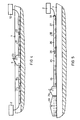
- the assembly steps according to Figure 1 can also outside of The route should be designed so that several individual lengths are combined into one Sub-section of about 100 m, for example, put together and leave this subsection next to the route becomes.
- such a subsection can also be done be made that several built from individual lengths Part lengths 14, 15, previously in a stationary assembly station to one closed at the ends with caps 31 Partial lengths have been connected to one next to the route Subsection to be merged. It also includes the use of a mobile assembly room 1 required in the one dried from one end of one of the two partial lengths Air by means of a device 2 for drying and compression is fed by air.
- the connection of two such subsections is done in principle in the same way as the connections of individual lengths.
- FIG. 4 there is another one Mobile assembly room 9 is provided, which is arranged in the route is and which is provided with a ventilation 23 and in which the two ends of subsections 16 and 17 are sealed are introduced.
- a device 2 and 10 for Drying and compression of air and for feeding it Air is arranged in the two subsections. In this way are the two subsections during the assembly of dried air flows through 21,22 to the in the assembly room ends of the subsections prevented from contamination and moisture.
Landscapes
- Chemical & Material Sciences (AREA)
- Oil, Petroleum & Natural Gas (AREA)
- Cable Accessories (AREA)
- Pipeline Systems (AREA)
- Laying Of Electric Cables Or Lines Outside (AREA)
Description
- Figur 1
- in schematischer Darstellung das Aneinanderfügen mehrerer Einzellängen,
- Figur 2
- das Aneinanderfügen mehrerer vorgefertigter Teillängen,
- Figur 3
- das Einbringen eines Unterabschnittes in einer als Graben ausgebildeten Trasse,
- Figur 4
- das Verbinden zweier Unterabschnitte in einer Trasse und
- Figur 5
- die Verbindung von Einzellängen der äußeren Kapselung und das nachträgliche Einbringen des Innenleiters.
Claims (4)
- Verfahren zum Errichten einer gekapselten, gasisolierten Rohrleiter- Kabelanlage unter Aufrechterhaltung einer reinen Gasatmosphäre im Innern der Kapselung während deren Verlegung,
bei dem staub- und gasdicht abgeschlossene Einzellängen (11,12,13) der Kapselung - mit oder ohne eingesetzte Energieleiter - Schritt für Schritt miteinander zu einem Anlagenabschnitt (16) verbunden werden,
dadurch gekennzeichnet, daß bei der Verbindung der Einzellängen (11,12,13) eine ständige Strömung (20) trockener Luft von dem einen Ende der ersten Einzellänge (11) zum Ende der jeweils letzten angesetzten Einzellänge (12) hin aufrechterhalten wird,wobei jeweils der zu verbindende Bereich zweier Einzellängen (12,13) von einem abgeschlossenen Montageraum (1) umgeben wird, aus dem während der Herstellung der Verbindung die aus den bereits verbundenen Einzellängen ausströmende getrocknete Luft abgesaugt (3) wird. - Verfahren nach Anspruch 1, bei dem miteinander verbundene Einzellängen in einen Graben abgelegt werden,
dadurch gekennzeichnet,daß zunächst mehrere Einzellängen außerhalb des Grabens (7) zu einem Unterabschnitt (17) mit einer Länge von etwa 100 m verbunden und die Enden des Unterabschnittes verschlossen werden und danach dieser Unterabschnitt (17) als Ganzes in den Graben (7) gelegt wird,daß anschließend ein zweiter Unterabschnitt (16) montiert, in den Graben (7) gelegt und mit dem ersten Unterabschnitt (17) verbunden wird und nachfolgend weitere Unterabschnitte montiert, in den Graben gelegt und mit dem jeweils vorhergehenden Unterabschnitt verbunden werdenund daß beim Verbinden zweier Unterabschnitte (16,17) von wenigstens einem der äußeren Enden der beiden Unterabschnitte her ein trockener Luftstrom (21,22) zur Verbindungsstelle hin aufrecht erhalten wird,wobei der Verbindungsbereich der beiden Unterabschnitte von einem abgeschlossenen Montageraum (9) umgeben wird, aus dem die aus den beiden Unterabschnitten ausströmende Luft abgesaugt (23) wird. - Verfahren nach Anspruch 2,
dadurch gekennzeichnet,daß bei der Verbindung der Einzellängen zu einem Unterabschnitt zunächst nur die Einzellängen (24,25,26,27) der äußeren Kapselungsrohre miteinander verbunden werden und hierbei der trockene Luftstrom (28) aufrechterhalten wirdund daß anschließend innerhalb des Montageraumes (29) die Innenleiter-Einzellängen (19) unter Aufrechterhaltung des trokkenen Luftstromes nacheinander in den Unterabschnitt der Kapselungsrohre eingeschoben und miteinander verbunden werden. - Verfahren nach einem der Ansprüche 1 bis 3,
dadurch gekennzeichnet, daß während der Verbindung der äußeren Kapselungsrohre durch Verschweißen die Strömung (20,21,22,28) der trockenen Luft unterbrochen wird.
Applications Claiming Priority (3)
| Application Number | Priority Date | Filing Date | Title |
|---|---|---|---|
| DE19627381 | 1996-06-27 | ||
| DE19627381A DE19627381A1 (de) | 1996-06-27 | 1996-06-27 | Verfahren zum Installieren einer gasisolierten Rohrleiter-Kabelanlage |
| PCT/DE1997/001361 WO1998000897A1 (de) | 1996-06-27 | 1997-06-26 | Verfahren zum installieren einer gasisolierten rohrleiter-kabelanlage |
Publications (2)
| Publication Number | Publication Date |
|---|---|
| EP0907996A1 EP0907996A1 (de) | 1999-04-14 |
| EP0907996B1 true EP0907996B1 (de) | 2002-01-02 |
Family
ID=7799182
Family Applications (1)
| Application Number | Title | Priority Date | Filing Date |
|---|---|---|---|
| EP97931681A Expired - Lifetime EP0907996B1 (de) | 1996-06-27 | 1997-06-26 | Verfahren zum installieren einer gasisolierten rohrleiter-kabelanlage |
Country Status (4)
| Country | Link |
|---|---|
| EP (1) | EP0907996B1 (de) |
| AT (1) | ATE211589T1 (de) |
| DE (2) | DE19627381A1 (de) |
| WO (1) | WO1998000897A1 (de) |
Families Citing this family (3)
| Publication number | Priority date | Publication date | Assignee | Title |
|---|---|---|---|---|
| DE102008037110A1 (de) * | 2008-08-06 | 2010-02-11 | Siemens Aktiengesellschaft | Montageverfahren für miteinander zu verbindende Segmente einer gasisolierten elektrischen Leitung sowie Magazineinrichtung zur Durchführung des Verfahrens |
| DE102015201659A1 (de) * | 2015-01-30 | 2016-08-04 | Siemens Aktiengesellschaft | Verfahren und Vorrichtung zum Verlegen von gasisolierten Rohrleitern. |
| DE102016213245A1 (de) * | 2016-07-20 | 2018-01-25 | Siemens Aktiengesellschaft | Verfahren zum Installieren einer gasisolierten elektrischen Übertragungsleitung |
Family Cites Families (5)
| Publication number | Priority date | Publication date | Assignee | Title |
|---|---|---|---|---|
| US1866611A (en) * | 1929-05-23 | 1932-07-12 | American Telephone & Telegraph | Concentric conducting system |
| CH548657A (de) * | 1972-08-23 | 1974-04-30 | Bbc Brown Boveri & Cie | Gerade teilstuecke aufweisende elektrische hochspannungsleitung. |
| DE2731560A1 (de) * | 1977-07-13 | 1979-01-25 | Kabel Metallwerke Ghh | Gasisolierte elektrische energieuebertragungsleitung |
| FR2692084B1 (fr) * | 1992-06-03 | 1994-07-22 | Alsthom Gec | Ligne blindee triphasee et son procede de fabrication. |
| FR2716751B1 (fr) * | 1994-02-25 | 1996-03-29 | Gec Alsthom T & D Sa | Procédé et dispositif pour la pose d'une ligne de transport à isolation gazeuse. |
-
1996
- 1996-06-27 DE DE19627381A patent/DE19627381A1/de not_active Withdrawn
-
1997
- 1997-06-26 EP EP97931681A patent/EP0907996B1/de not_active Expired - Lifetime
- 1997-06-26 DE DE59706106T patent/DE59706106D1/de not_active Expired - Fee Related
- 1997-06-26 AT AT97931681T patent/ATE211589T1/de not_active IP Right Cessation
- 1997-06-26 WO PCT/DE1997/001361 patent/WO1998000897A1/de not_active Ceased
Also Published As
| Publication number | Publication date |
|---|---|
| DE59706106D1 (de) | 2002-02-28 |
| EP0907996A1 (de) | 1999-04-14 |
| DE19627381A1 (de) | 1998-01-02 |
| ATE211589T1 (de) | 2002-01-15 |
| WO1998000897A1 (de) | 1998-01-08 |
Similar Documents
| Publication | Publication Date | Title |
|---|---|---|
| DE69601616T2 (de) | Installationsverfahren für ein Abzweigröhrensystem bei Telekommunikationskabeln und Abzweigelement zum Gebrauch bei besagtem Verfahren | |
| DE3145896C2 (de) | Kunststoffisolator | |
| DE3943296A1 (de) | Muffe zum einhuellen einer verbindung oder eines endes eines elektrokabels | |
| DE69011266T2 (de) | Gekapselte elektrische Leitung und Verfahren zu seiner Herstellung. | |
| DE2245745A1 (de) | Aus geraden teilstuecken zusammengesetzte elektrische hochspannungsleitung | |
| EP0475417B1 (de) | Anordnung von Führungselementen für elektrische Leitungen im Fassadenbereich von Gebäuden | |
| DE3536250C2 (de) | ||
| EP0907996A1 (de) | Verfahren zum installieren einer gasisolierten rohrleiter-kabelanlage | |
| DE2233217A1 (de) | Trommelbare kabellaenge eines gasisolierten hochspannungskabels | |
| EP0525600B1 (de) | Kabelschutzanordnung für oder an eine im Erdboden zu verlegende und an Gebäude, Ziehkästen oder dergleichen anschliessbare Leitungsanordnung | |
| DE10042952C2 (de) | Teilbare Einzelzugabdichtung für Kabel | |
| DE69210131T2 (de) | Anordnung zum Verbinden zweier Kabel für hohe oder sehr hohe Spannung | |
| DE1059527B (de) | Kabelmuffe aus einem aushaertenden Giessharz fuer unter Gasinnendruck stehende mehradrige Fernmeldekabel mit kunststoffisolierten Adern und mit einem insbesondere aus Kunststoff bestehenden Kabelmantel | |
| DE1490177B2 (de) | Verfahren und Einrichtung zum Herstellen einer Kabelverbindung bei einem Mehrleiter-Ölkabel mit Ölkanälen in den Zwickelräumen sowie danach hergestellte Kabelverbindung | |
| DE4438228A1 (de) | Kabelverbindungs- und/oder Kabelabzweigmuffe für Energie- und Fernmeldekabel, Verfahren zum Herstellen der Abdichtung von deren Kabelverbindungs- und Kabelabzweigstellen sowie Füllmasse als Abdichtmittel | |
| EP1052755A2 (de) | Kabeldurchführung | |
| DE3738203C2 (de) | ||
| DE3627600C2 (de) | Verfahren und Vorrichtung zum Regenerieren von Starkstromkabeln | |
| DE1170501C2 (de) | Metallgekapselte Hochspannungsschaltanlage | |
| DE3738204A1 (de) | Kabelverteiler bzw. -abzweiger | |
| WO2011042278A2 (de) | Muffe zur verbindung der enden von wicklungen eines langstator-linearmotors und damit ausgerüsteter langstator | |
| DE2604650A1 (de) | Geschirmtes mittelspannungskabel mit endmuffe | |
| DE3010083C2 (de) | ||
| DE2310999C3 (de) | Kabelspleißgehäuse | |
| DE102017204930B4 (de) | Elektrisches Gerät zum Anschluss an ein Hochspannungsnetz |
Legal Events
| Date | Code | Title | Description |
|---|---|---|---|
| PUAI | Public reference made under article 153(3) epc to a published international application that has entered the european phase |
Free format text: ORIGINAL CODE: 0009012 |
|
| 17P | Request for examination filed |
Effective date: 19981217 |
|
| AK | Designated contracting states |
Kind code of ref document: A1 Designated state(s): AT CH DE FR GB LI |
|
| GRAG | Despatch of communication of intention to grant |
Free format text: ORIGINAL CODE: EPIDOS AGRA |
|
| RTI1 | Title (correction) |
Free format text: PROCESS FOR INSTALLING A CABLE SYSTEM INSULATED BY GAS |
|
| GRAG | Despatch of communication of intention to grant |
Free format text: ORIGINAL CODE: EPIDOS AGRA |
|
| GRAH | Despatch of communication of intention to grant a patent |
Free format text: ORIGINAL CODE: EPIDOS IGRA |
|
| 17Q | First examination report despatched |
Effective date: 20010515 |
|
| GRAH | Despatch of communication of intention to grant a patent |
Free format text: ORIGINAL CODE: EPIDOS IGRA |
|
| GRAA | (expected) grant |
Free format text: ORIGINAL CODE: 0009210 |
|
| REG | Reference to a national code |
Ref country code: GB Ref legal event code: IF02 |
|
| AK | Designated contracting states |
Kind code of ref document: B1 Designated state(s): AT CH DE FR GB LI |
|
| PG25 | Lapsed in a contracting state [announced via postgrant information from national office to epo] |
Ref country code: GB Free format text: LAPSE BECAUSE OF FAILURE TO SUBMIT A TRANSLATION OF THE DESCRIPTION OR TO PAY THE FEE WITHIN THE PRESCRIBED TIME-LIMIT Effective date: 20020102 |
|
| REF | Corresponds to: |
Ref document number: 211589 Country of ref document: AT Date of ref document: 20020115 Kind code of ref document: T |
|
| REG | Reference to a national code |
Ref country code: CH Ref legal event code: EP |
|
| REG | Reference to a national code |
Ref country code: CH Ref legal event code: NV Representative=s name: SIEMENS SCHWEIZ AG |
|
| REF | Corresponds to: |
Ref document number: 59706106 Country of ref document: DE Date of ref document: 20020228 |
|
| ET | Fr: translation filed | ||
| PG25 | Lapsed in a contracting state [announced via postgrant information from national office to epo] |
Ref country code: AT Free format text: LAPSE BECAUSE OF NON-PAYMENT OF DUE FEES Effective date: 20020626 |
|
| PLBE | No opposition filed within time limit |
Free format text: ORIGINAL CODE: 0009261 |
|
| STAA | Information on the status of an ep patent application or granted ep patent |
Free format text: STATUS: NO OPPOSITION FILED WITHIN TIME LIMIT |
|
| 26N | No opposition filed | ||
| PGFP | Annual fee paid to national office [announced via postgrant information from national office to epo] |
Ref country code: FR Payment date: 20040618 Year of fee payment: 8 |
|
| PGFP | Annual fee paid to national office [announced via postgrant information from national office to epo] |
Ref country code: DE Payment date: 20040819 Year of fee payment: 8 |
|
| PGFP | Annual fee paid to national office [announced via postgrant information from national office to epo] |
Ref country code: CH Payment date: 20040908 Year of fee payment: 8 |
|
| PG25 | Lapsed in a contracting state [announced via postgrant information from national office to epo] |
Ref country code: LI Free format text: LAPSE BECAUSE OF NON-PAYMENT OF DUE FEES Effective date: 20050630 Ref country code: CH Free format text: LAPSE BECAUSE OF NON-PAYMENT OF DUE FEES Effective date: 20050630 |
|
| PG25 | Lapsed in a contracting state [announced via postgrant information from national office to epo] |
Ref country code: DE Free format text: LAPSE BECAUSE OF NON-PAYMENT OF DUE FEES Effective date: 20060103 |
|
| REG | Reference to a national code |
Ref country code: CH Ref legal event code: PL |
|
| PG25 | Lapsed in a contracting state [announced via postgrant information from national office to epo] |
Ref country code: FR Free format text: LAPSE BECAUSE OF NON-PAYMENT OF DUE FEES Effective date: 20060228 |
|
| REG | Reference to a national code |
Ref country code: FR Ref legal event code: ST Effective date: 20060228 |