EP0907605B1 - Telescopic platform for receipt of loads - Google Patents
Telescopic platform for receipt of loads Download PDFInfo
- Publication number
- EP0907605B1 EP0907605B1 EP97925055A EP97925055A EP0907605B1 EP 0907605 B1 EP0907605 B1 EP 0907605B1 EP 97925055 A EP97925055 A EP 97925055A EP 97925055 A EP97925055 A EP 97925055A EP 0907605 B1 EP0907605 B1 EP 0907605B1
- Authority
- EP
- European Patent Office
- Prior art keywords
- slide
- base
- carriage
- drive device
- telescopic
- Prior art date
- Legal status (The legal status is an assumption and is not a legal conclusion. Google has not performed a legal analysis and makes no representation as to the accuracy of the status listed.)
- Expired - Lifetime
Links
- 230000001133 acceleration Effects 0.000 description 3
- 230000004308 accommodation Effects 0.000 description 2
- 238000006073 displacement reaction Methods 0.000 description 2
- 238000012423 maintenance Methods 0.000 description 2
- 230000005540 biological transmission Effects 0.000 description 1
- 238000011161 development Methods 0.000 description 1
- 230000018109 developmental process Effects 0.000 description 1
- 230000000694 effects Effects 0.000 description 1
- 230000005611 electricity Effects 0.000 description 1
- 239000012530 fluid Substances 0.000 description 1
Images
Classifications
-
- B—PERFORMING OPERATIONS; TRANSPORTING
- B66—HOISTING; LIFTING; HAULING
- B66F—HOISTING, LIFTING, HAULING OR PUSHING, NOT OTHERWISE PROVIDED FOR, e.g. DEVICES WHICH APPLY A LIFTING OR PUSHING FORCE DIRECTLY TO THE SURFACE OF A LOAD
- B66F9/00—Devices for lifting or lowering bulky or heavy goods for loading or unloading purposes
- B66F9/06—Devices for lifting or lowering bulky or heavy goods for loading or unloading purposes movable, with their loads, on wheels or the like, e.g. fork-lift trucks
- B66F9/075—Constructional features or details
- B66F9/12—Platforms; Forks; Other load supporting or gripping members
- B66F9/14—Platforms; Forks; Other load supporting or gripping members laterally movable, e.g. swingable, for slewing or transverse movements
- B66F9/141—Platforms; Forks; Other load supporting or gripping members laterally movable, e.g. swingable, for slewing or transverse movements with shuttle-type movement
-
- A—HUMAN NECESSITIES
- A47—FURNITURE; DOMESTIC ARTICLES OR APPLIANCES; COFFEE MILLS; SPICE MILLS; SUCTION CLEANERS IN GENERAL
- A47B—TABLES; DESKS; OFFICE FURNITURE; CABINETS; DRAWERS; GENERAL DETAILS OF FURNITURE
- A47B11/00—Tables with tops revolvable on vertical spindles
-
- B—PERFORMING OPERATIONS; TRANSPORTING
- B65—CONVEYING; PACKING; STORING; HANDLING THIN OR FILAMENTARY MATERIAL
- B65G—TRANSPORT OR STORAGE DEVICES, e.g. CONVEYORS FOR LOADING OR TIPPING, SHOP CONVEYOR SYSTEMS OR PNEUMATIC TUBE CONVEYORS
- B65G1/00—Storing articles, individually or in orderly arrangement, in warehouses or magazines
Definitions
- the invention relates to a telescopic table with a base and, on this telescopically linearly guided, at least two sledges and a shooting table as well as at least two drive devices arranged on the base, one of which connected to the first carriage by drive means alone and operates its second ropes and / or chain hoists, which move the second or further slide and the recording table.
- Such telescopic tables are used, for example, for loading in high-bay warehouses whose compartments are stacked with goods and for removal Goods used.
- the length of the retracted telescopic table is limited by the width of the aisle between the shelves; but often, in addition to normal, oversized exit routes required, for example, in a deep shelf compartment, for example two pallets are to be stored one after the other, or special circumstances are present, e.g. B. a fire wall is provided.
- EP 0 410 286 A2 proposes to overcome these disadvantages the extension of the recording table and on it subsequent sled not in parallel, as usual, in time to effect or synchronously, but by locking devices controlled one after the other so that, for example, with short travel distances of the recording table first this recording table, then the one load-bearing carriages etc. are moved until the desired stroke is reached.
- the locking devices make it unfavorable here required effort as noticeable as the through the respective acceleration and deceleration of the telescopic members conditional uneasy run of the recording table as well as that of one such operation limited exit speed.
- PCT-WO 94/04 447 relates to container receivers Carrying forks and revealed another way, too short extension paths provided instead of a shooting table Pick-up fork whose distance to the next slide is large Hold:
- the carriage guided on the base becomes two drive devices assigned, one of which is the shift of Sled and their other the displacement of the shooting table or the pick-up fork against the following carriage, wherein a drive device has different ratios having or switchable gear can be effective.
- FR-A-2 709 745 discloses a telescopic table which is used for advancing of sledges and the shooting table with two, in the Base housed drive devices is equipped that each drive an endless chain.
- One of these chains is with the first sled, the second with another endless band connected, which in turn with an endless band in the following sledge is connected. It can be used for sledges Extend controlled use, the use Anchors extending across chains to connect them however, affects the accuracy of the control and the Adjustable drive torques.
- the invention is therefore based on the task of a telescopic table to create the designated genus, even in the case of smaller ones Exit paths at least the shooting table on the one leading him Slide is largely or fully extended, and in which the respective exit paths can be determined and with high accelerations are passable.
- the assembly and feeding of the electricity or the hydraulic fluid can be lightened as well as the Maintenance can be carried out easily and securely, so that in the company there are long service lives.
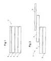
- a telescopic table 1 is schematically in its starting position shown in the above its base 2 a first Carriage 3, a second carriage 4 and table 5 practical stand flush.
- the telescopic table 1 of Figure 1 is part of the maximum extension distance shown, the of first carriages 3 operated by a first drive device is still flush with the base 2, the second carriage 4 and the Recording table 5, however, by a second drive device are fully extended. But this overhangs the shooting table 5 and the sled 4, the sled 3 maximum, and the The end face of this slide is against that of the extended one Telescopic links maximally withdrawn.
- Figure 3 shows that by loading the first drive device now the carriage 3 is extended against the base 2 and thus the maximum extension length of the receiving table 5 are reached.
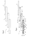
- FIG. 4 again shows the telescopic table 1 schematically on the base 2 extended slide 3, slide 4 and recording table 5.
- To move the carriage 3 is one by one Not shown drive motor rotatable pinion 6 provided that engages in a chain 7.
- This chain shown in dashed lines is placed around pulleys 8 and 9, and their free ends are led crosswise and fixed in two places of the carriage 3. If the pinion 6 is now driven, the chain moved in one of two possible directions, the one free end of the chain 7 is tightened and the other gives way.
- the carriage 3 connected to the two ends of the chain will hence along its guidance in base 2, which for relief the overview in Figure 4 is not shown from its linear position.
- the base 2 is also with another drive device equipped, which is also not shown, and the one carriage 10 in one indicated by horizontal lines to move horizontal guidance within base 2 can
- the carriage 10 carries, rotatably mounted on an axis Double pinion 11.
- One dot-dash with three dots each Draw chain 12 is single ended with a chain tensioner 13 set, from this towards the double pinion 11th led and looped around this by about 180 °.
- From the double pinion 11 is the pull chain 12 by another, at the end of the base 2nd stored deflection pinion 14 guided, from this to the opposite Side of the carriage 3 over one on its opposite End-mounted deflection pinion 15 looped and from this in turn led to the opposite side of the carriage 4 and associated with this.
- a dash-dotted line is approximately symmetrical to this Draw chain 16 shown on a chain tensioner 17th fixed at one end, via the second pinion of the double pinion 11 looped and guided by this to the deflection pinion 18, the the end of the base 2 opposite the deflection pinion 14 is stored. From here is the pull chain 16, the pull chain 12 crossing to one at the opposite end of the slide 3 stored deflection pinion 19, and, the pull chain 12 again crossing, connected to the slide 4 near the end. That means Now the following: Is by means of the second, not shown Drive device of the carriage 10, for example, shifted to the right, this is how the loop of the pull chain is guided around the double pinion 11 12 shortened and the end guided around the deflection pinion 14 and 15 this pull chain extended.
- the Carriage 3 is finely dashed with the receiving table 5 by two shown pull chains 20 and 21 connected, initially crossed and guided over pulleys 22 and 23, which are mounted on the two ends of the carriage 4. Means this deflection pinion 22 and 23 deflected, the free end regions the pull chains 20, 21 crossed again, and their ends are connected to the receiving table 5. This makes movements between the slides 4 and 3 also on the receiving table 5 transferred with respect to the carriage 4.
- the shooting table 5 in guides of the Slide 4 this in guides of the slide 3 and this in turn in guides of the base 2 linearly, and by Control means of the drives and / or by restricting the movements Stops are the extension distances of the individual telescopic links limited.
- the drive means are also advantageous to avoid the linear feed impairing Moments executed twice and arranged symmetrically.
Landscapes
- Engineering & Computer Science (AREA)
- Structural Engineering (AREA)
- Transportation (AREA)
- Mechanical Engineering (AREA)
- Life Sciences & Earth Sciences (AREA)
- Geology (AREA)
- Civil Engineering (AREA)
- Transmission Devices (AREA)
- Forklifts And Lifting Vehicles (AREA)
- Warehouses Or Storage Devices (AREA)
- Accommodation For Nursing Or Treatment Tables (AREA)
- Handcart (AREA)
- Motorcycle And Bicycle Frame (AREA)
- Constitution Of High-Frequency Heating (AREA)
- Refuge Islands, Traffic Blockers, Or Guard Fence (AREA)
Abstract
Description
Die Erfindung betrifft einen Teleskoptisch mit einer Basis und, auf dieser teleskopartig linear verschiebbar geführten, mindestens zwei Schlitten und einem Aufnahmetisch sowie mindestens zwei auf der Basis angeordneten Antriebsvorrichtungen, deren eine über Antriebsmittel allein mit dem ersten Schlitten verbunden ist, und deren zweite Seile und/oder Kettenzüge betreibt, welche den zweiten bzw. weitere Schlitten sowie den Aufnahmetisch verschieben.The invention relates to a telescopic table with a base and, on this telescopically linearly guided, at least two sledges and a shooting table as well as at least two drive devices arranged on the base, one of which connected to the first carriage by drive means alone and operates its second ropes and / or chain hoists, which move the second or further slide and the recording table.
Derartige Teleskoptische werden bspw. bei Hochregallagern zur Beschickung deren Fächer mit Waren und zur Entnahme gestapelter Waren benutzt. Die Länge des eingefahrenen Teleskoptisches ist hierbei durch die Breite des Ganges zwischen den Regalen begrenzt; oft aber werden neben normalen übergroße Ausfahrwege verlangt, wenn bspw. in einem tiefen Regalfach bspw. zwei Paletten hintereinander einzulagern sind, oder besondere Verhältnisse vorliegen, z. B. eine Brandschutzwand vorgesehen ist. Zwar ist es prinzipiell möglich, neben dem optimalen Ausfahren der einzelnen Schlitten und des Aufnahmetisches durch Teilwege derselben auch geringere Ausfahrwege zu bewirken, hierbei stehen jedoch bei üblichen Ausbildungen der Antriebsvorrichtungen der Schlitten und des Aufnahmetisches die Stirnflächen bspw. des Aufnahmetisches und der diesem folgenden zwei Schlitten in so geringem Abstande hintereinander, daß oft die beiden den Aufnahmetisch stützenden Schlitten bei geringeren Ausfahrwegen mit in das Regalfach einzutreten haben und daher bei der Stützhöhe der zu übernehmenden Last die Höhe sowohl des Aufnahmeschiebers als auch der diesen führenden Schlitten zu berücksichtigen sind.Such telescopic tables are used, for example, for loading in high-bay warehouses whose compartments are stacked with goods and for removal Goods used. The length of the retracted telescopic table is limited by the width of the aisle between the shelves; but often, in addition to normal, oversized exit routes required, for example, in a deep shelf compartment, for example two pallets are to be stored one after the other, or special circumstances are present, e.g. B. a fire wall is provided. Is it is possible in principle, in addition to the optimal extension of the individual Sled and the shooting table through partial paths of the same to bring about shorter travel distances, however, usual training of the drive devices of the carriage and the end faces of the recording table, for example the recording table and the following two sledges at such a short distance one after the other that often the two supporting the recording table Sled to enter the shelf compartment with smaller travel distances have and therefore with the support height of the to be taken over Load the height of both the take-up slide and this leading sled must be considered.
In der EP 0 410 286 A2 wird zur Behebung dieser Nachteile vorgeschlagen, das Ausfahren des Aufnahmetisches und der an diesen anschließenden Schlitten nicht, wie üblich, zeitlich parallel bzw. synchron zu bewirken, sondern durch Riegelvorrichtungen gesteuert nacheinander, so daß bspw. bei geringen Ausfahrwegen des Aufnahmetisches zunächst dieser Aufnahmetisch, sodann der ihn tragende Schlitten usw. bewegt werden, bis der gewünschte Hub erreicht ist. Ungünstig machen sich hierbei der durch die Riegelvorrichtungen benötigte Aufwand ebenso bemerkbar wie der durch das jeweilige Beschleunigen und Verzögern der Teleskopglieder bedingte unruhige Lauf des Aufnahmetisches sowie die durch einen solchen Betrieb begrenzte Ausfahrgeschwindigkeit.EP 0 410 286 A2 proposes to overcome these disadvantages the extension of the recording table and on it subsequent sled not in parallel, as usual, in time to effect or synchronously, but by locking devices controlled one after the other so that, for example, with short travel distances of the recording table first this recording table, then the one load-bearing carriages etc. are moved until the desired stroke is reached. The locking devices make it unfavorable here required effort as noticeable as the through the respective acceleration and deceleration of the telescopic members conditional uneasy run of the recording table as well as that of one such operation limited exit speed.
Die PCT-WO 94/04 447 bezieht sich auf Container aufnehmende Traggabeln und offenbart eine weitere Möglichkeit, auch bei geringen Ausfahrwegen der statt eines Aufnahmetisches vorgesehenen Aufnahmegabel deren Abstand zum folgenden Schlitten groß zu halten: Dem auf der Basis geführten Schlitten werden zwei Antriebsvorrichtungen zugeordnet, deren eine die Verschiebung der Schlitten und deren andere die Verschiebung des Aufnahmetisches bzw. der Aufnahmegabel gegen den folgenden Schlitten bestimmen, wobei eine Antriebsvorrichtung über unterschiedliche Übersetzungen aufweisende bzw. schaltbare Getriebe wirksam werden kann. Damit läßt sich zwar der Aufnahmetisch bzw. die Aufnahmegabel stets voll gegen den sie tragenden und führenden Schlitten ausfahren, aber schon die Unterbringung der Antriebsvorrichtungen und deren Energiezuleitungen sowie der diesen nachgeordneten Getriebe in einem Schlitten bietet erhebliche Schwierigkeiten, und auch die Übertragung der Bewegung zum Aufnahmetisch bzw. der Aufnahmegabel über gegebenenfalls weitere Schlitten erweist sich als unliebsam kompliziert und störanfällig.PCT-WO 94/04 447 relates to container receivers Carrying forks and revealed another way, too short extension paths provided instead of a shooting table Pick-up fork whose distance to the next slide is large Hold: The carriage guided on the base becomes two drive devices assigned, one of which is the shift of Sled and their other the displacement of the shooting table or the pick-up fork against the following carriage, wherein a drive device has different ratios having or switchable gear can be effective. This allows the recording table or the fork always extend fully against the sled that carries and guides them, but already the accommodation of the drive devices and their energy supply lines and their subordinate ones Gearbox in a sled presents considerable difficulties and also the transmission of the movement to the recording table or the Pick-up fork over any other sled turns out to be as unpleasantly complicated and prone to failure.
Die FR-A-2 709 745 offenbart einen Teleskoptisch, der zum Vorschieben von Schlitten sowie des Aufnahmetisches mit zwei, in der Basis untergebrachten Antriebsvorrichtungen ausgestattet ist, die jeweils eine endlose Kette antreiben. Eine dieser Ketten ist mit dem ersten Schlitten, die zweite mit einem weiteren endlosen Band verbunden, das seinerseits wiederum mit einem endlosen Band im folgenden Schlitten verbunden ist. Damit lassen sich zwar Schlitten gesteuert unterschiedlich weit ausschieben, die Verwendung sich quer zu Ketten erstreckender Anker zu deren Verbindung beeinträchtigt jedoch die Genauigkeit der Steuerung sowie die zum Verstellen bewirkbaren Antriebsmomente.FR-A-2 709 745 discloses a telescopic table which is used for advancing of sledges and the shooting table with two, in the Base housed drive devices is equipped that each drive an endless chain. One of these chains is with the first sled, the second with another endless band connected, which in turn with an endless band in the following sledge is connected. It can be used for sledges Extend controlled use, the use Anchors extending across chains to connect them however, affects the accuracy of the control and the Adjustable drive torques.
Die Erfindung geht daher von der Aufgabe aus, einen Teleskoptisch der bezeichneten Gattung zu schaffen, bei dem auch bei geringeren Ausfahrwegen zumindest der Aufnahmetisch auf dem ihn führenden Schlitten weitgehend bzw. voll ausgefahren ist, und bei dem die jeweiligen Ausfahrwege bestimmbar sind sowie mit hohen Beschleunigungen durchfahrbar sind. Durch die Unterbringung der Antriebsvorrichtungen sollen die Montage und die Einspeisung des Stromes oder des Hydraulikmittels ebenso erleichtert werden, wie auch die Wartung einfach und gesichert durchführbar wird, so daß im Betriebe sich hohe Standzeiten ergeben.The invention is therefore based on the task of a telescopic table to create the designated genus, even in the case of smaller ones Exit paths at least the shooting table on the one leading him Slide is largely or fully extended, and in which the the respective exit paths can be determined and with high accelerations are passable. By housing the drive devices the assembly and feeding of the electricity or the hydraulic fluid can be lightened as well as the Maintenance can be carried out easily and securely, so that in the company there are long service lives.
Gelöst wird diese Aufgabe durch die im Patentanspruch 1 aufgeführten Merkmale. Diese sichern einen relativ einfachen Aufbau, und die jeweiligen Beschleunigungskräfte werden rein durch Kettenzug übertragen, so daß auch größere Kräfte praktisch ohne elastische Dehnung bzw. Nachgiebigkeit übertragbar sind. Damit ist mit den separaten Antriebsvorrichtungen entweder der zweite sowie folgende Schlitten sowie der Aufnahmetisch auszuschieben oder, zur Erzielung größerer Ausschubweiten, zusätzlich der arste Schlitten auf der Basis auszuschieben, so daß für die praktisch benötigten Ausschubweiten stets der Aufnahmetisch, zweckmäßig mit dem zweiten Schlitten, voll ausgefahren sind, während der erste Schlitten nur dann zusätzlich mit ausgefahren wird, wenn die zu erzielende Ausschubweite dies erfordert. Damit aber wird der Aufgabe gemäß die Höhe der bei geringeren Ausfahrwegen in ein Regalfach einfahrenden Teleskopglieder vorteilhaft begrenzt, so daß aufwendige Unterklotzungen eingelagerter Lasten eingespart werden, wobei durch die Anordnung der Antriebsvorrichtungen in der Basis sowohl ausreichend Raum für deren Unterbringung zur Verfügung steht als auch durch Strom- und/oder Druckmittelzuleitungen, die in der Basis stationär verlegbar sind, Komplikationen nicht zu erwarten sind. Die feste Unterbringung in der geräumigen Basis erlaubt nicht nur eine schnelle, einfache und sichere Montage, sondern vereinfacht auch die spätere Wartung, so daß erwünscht lange Standzeiten und ein zuverlässiger, störungsarmer Betrieb zu erwarten sind.This object is achieved by those listed in claim 1 Characteristics. These ensure a relatively simple structure, and the respective acceleration forces are purely by chain hoist transferred, so that even larger forces practically without elastic stretch or compliance are transferable. In order to is either the second with the separate drive devices as well as the following sledge and the shooting table or, in order to achieve larger extension widths, the poorest Slide out the sled base, so practical for that required extension widths always the shooting table, conveniently with the second sled, are fully extended while the first Sledge is only extended when the is closed extending range requires this. But with that the Task according to the height of the with smaller extension paths in one Retractable telescopic links retracting advantageously limited, so that costly blocks of stored loads are saved be, by the arrangement of the drive devices in the base both have enough space to accommodate them Is available as well as through power and / or pressure medium supply lines, complications that are stationary in the base are not expected. Fixed accommodation in the spacious Basis not only allows a quick, easy and safe Assembly, but also simplifies subsequent maintenance, so that Long service life and a reliable, low-interference are desired Operation are expected.
Zweckmäßige, vorteilhafte und erfinderische Weiterbildungen sind in den Unteransprüchen gekennzeichnet.Practical, advantageous and inventive developments are characterized in the subclaims.
Im einzelnen sind die Merkmale der Erfindung anhand der Beschreibung eines Ausführungsbeispiels in Verbindung mit dieses erläuternden Zeichnungen dargestellt. Es zeigen hierbei:
- Figur 1
- schematisch einen Teleskoptisch in der Ruhestellung,
Figur 2- den Teleskoptisch der Figur 1 teilweise ausgeschoben,
Figur 3- den Teleskoptisch der Figur 1 maximal ausgeschoben, und
Figur 4- schematisch den Aufbau des Teleskoptisches der Figuren 1 bis 3.
- Figure 1
- schematically a telescopic table in the rest position,
- Figure 2
- partially extended the telescopic table of FIG. 1,
- Figure 3
- the telescopic table of Figure 1 pushed out to the maximum, and
- Figure 4
- schematically the structure of the telescopic table of Figures 1 to 3.
In Figur 1 ist ein Teleskoptisch 1 schematisch in seiner Ausgangsstellung
gezeigt, in der über seiner Basis 2 ein erster
Schlitten 3, ein zweiter Schlitten 4 und Aufnahmetisch 5 praktisch
bündig stehen.In Figure 1, a telescopic table 1 is schematically in its starting position
shown in the above its base 2 a
In Figur 2 ist der Teleskoptisch 1 der Figur 1 auf einen Teil des
maximalen Ausfahrweges ausgefahren dargestellt, wobei der von
einer ersten Antriebsvorrichtung betriebene erste Schlitten 3
noch mit der Basis 2 bündig steht, der zweite Schlitten 4 und der
Aufnahmetisch 5 jedoch durch eine zweite Antriebsvorrichtung
jeweils voll ausgefahren sind. Damit aber überkragen der Aufnahmetisch
5 und der Schlitten 4 den Schlitten 3 maximal, und die
Stirnfläche dieses Schlittens ist gegen die der ausgefahrenen
Teleskopglieder maximal zurückgetreten.In Figure 2, the telescopic table 1 of Figure 1 is part of the
maximum extension distance shown, the of
Figur 3 zeigt, daß durch Beaufschlagung der ersten Antriebsvorrichtung
nunmehr auch der Schlitten 3 gegen die Basis 2 ausgefahren
und somit die maximale Ausfahrlänge des Aufnahmetisches 5
erreicht sind. Figure 3 shows that by loading the first drive device
now the
Die Figur 4 zeigt wiederum schematisch den Teleskoptisch 1 mit
auf der Basis 2 ausgefahrenen Schlitten 3, Schlitten 4 und Aufnahmetisch
5. Zur Bewegung des Schlittens 3 ist ein durch einen
nicht dargestellten Antriebsmotor drehbares Ritzel 6 vorgesehen,
das in eine Kette 7 eingreift. Diese gestrichelt gezeigte Kette
ist um Umlenkritzel 8 und 9 gelegt, und ihre freien Enden sind
über Kreuz geführt und an zwei Stellen des Schlittens 3 festgelegt.
Wird nunmehr das Ritzel 6 angetrieben, so wird die Kette
in der einen zweier möglichen Richtungen bewegt, wobei das eine
freie Ende der Kette 7 angezogen wird und das andere nachgibt.
Der mit den beiden Enden der Kette verbundene schlitten 3 wird
damit entlang seiner Führung in der Basis 2, die zur Erleichterung
der Übersicht in Figur 4 nicht dargestellt ist, aus seiner
jeweiligen Position linear verschoben.FIG. 4 again shows the telescopic table 1 schematically
on the
Die Basis 2 ist aber auch noch mit einer weiteren Antriebsvorrichtung
ausgestattet, die ebenfalls nicht dargestellt ist, und
die einen Wagen 10 in einer durch horizontale Striche angedeuteten
horizontalen Führung innerhalb der Basis 2 zu verschieben
vermag. Der Wagen 10 trägt, auf einer Achse drehbar gelagert, ein
Doppelritzel 11. Eine mit jeweils drei Punkten strichpunktiert
gezeichnete Zugkette 12 ist einendig mit einen Kettenspanner 13
festgelegt, von diesem aus in Richtung auf das Doppelritzel 11
geführt und um etwa 180° um dieses geschlungen. Vom Doppelritzel
11 aus ist die Zugkette 12 um ein weiteres, am Ende der Basis 2
gelagertes Umlenkritzel 14 geführt, von diesem zur gegenüberliegenden
Seite des Schlittens 3 über ein an dessen gegenüberliegendem
Ende gelagertes Umlenkritzel 15 geschlungen und von
diesem aus wiederum zur Gegenseite des Schlittens 4 geführt und
mit diesem verbunden. Etwa symmetrisch hierzu ist eine strichpunktiert
dargestellte Zugkette 16 an einem Kettenspanner 17
einendig befestigt, über das zweite Ritzel des Doppelritzels 11
geschlungen und von diesem zum Umlenkritzel 18 geführt, das an
dem dem Umlenkritzel 14 gegenüberliegenden Ende der Basis 2
gelagert ist. Von hier aus ist die Zugkette 16, die Zugkette 12
kreuzend, zu einem am gegenüberliegenden Ende des Schlittens 3
gelagerten Umlenkritzel 19 geführt, und, die Zugkette 12 nochmals
kreuzend, in Endnähe mit dem Schlitten 4 verbunden. Das bedeutet
nunmehr folgendes: Wird mittels der nicht dargestellten zweiten
Antriebsvorrichtung der Wagen 10 bspw. nach rechts verschoben,
so wird die um das Doppelritzel 11 geführte Schlaufe der Zugkette
12 verkürzt und das um die Umlenkritzel 14 und 15 geführte Ende
dieser Zugkette verlängert. Gleichzeitig aber wird die von der
Zugkette 16 gebildete und um das Doppelritzel 11 gelegte Schlaufe
vergrößert, so daß über die Umlenkritzel 18 und 19 eine entsprechende
Länge der Zugkette 16 abgezogen und durch ihr freies Ende
der Schlitten 4 in seiner Linearführung nach rechts verschoben
wird.The
Diese Bewegung wird auch dem Aufnahmetisch 5 mitgeteilt: Der
Schlitten 3 ist mit dem Aufnahmetisch 5 durch zwei jeweils feingestrichelt
dargestellte Zugketten 20 und 21 verbunden, die zunächst
gekreuzt und über Umlenkritzel 22 und 23 geführt werden,
die an den beiden Enden des Schlittens 4 gelagert sind. Mittels
dieser Umlenkritzel 22 und 23 umgelenkt, werden die freien Endbereiche
der Zugketten 20, 21 nochmals gekreuzt, und ihre Enden
sind mit dem Aufnahmetisch 5 verbunden. Hierdurch werden Bewegungen
zwischen den Schlitten 4 und 3 auch auf den Aufnahmetisch 5
in Bezug auf den Schlitten 4 übertragen.This movement is also communicated to the recording table 5: the
Carriage 3 is finely dashed with the receiving table 5 by two
shown
Damit lassen sich durch Verschieben des Wagens 10 mittels der
nicht dargestellten zweiten Antriebsvorrichtung und mittels der
als Antriebsmittel vorgesehenen Zugketten 12, 16, 20 und 21 der
Schlitten 4 auf dem Schlitten 3 sowie der Aufnahmetisch 5 auf dem
Schlitten 4 entsprechend der Fig. 2 ausfahren, ohne daß die Lage
des Schlittens 3 zur Basis 2 geändert wird. Andererseits läßt
sich durch Beaufschlagung der ersten der nicht dargestellten
Antriebsvorrichtungen über das als Antriebsmittel dienenden
Ritzel 6 sowie Kette 7 die Stellung des Schlittens 3 auf der
Basis 2 verändern, wobei vermittels der Zugketten 12, 16, 20 und
21 durch die Verlagerung der Umlenkritzel 15 und 19 auch der
Schlitten 4 sowie der Aufnahmetisch 5 ausgeschoben werden. Das
bedeutet, daß wahlweise durch Beaufschlagung ausschließlich der
zweiten Antriebsvorrichtung Schlitten 4 und Aufnahmetisch 5
ausgefahren werden können, was üblicherweise für einen geringen
Ausschubbedarf zur Übernahme von in Regalfächern vorn liegender
Lasten ausreicht. Sollen weiter hinten liegende Lasten aufgenommen
oder abgegeben werden, so wird statt derer die erste Antriebsvorrichtung
beaufschlagt und der Schlitten 3 gegenüber der
Basis 2 sowie der Schlitten 4 und die der Aufnahmetisch 5 ausgefahren.
Im übrigen sind die Ausfahrmanöver der Teleskopglieder
nicht auf das vollständige Ausschieben allein des Schlittens 4
sowie des Aufnahmetisches 5 oder das Ausfahren aller Teleskopglieder
beschränkt, es können auch beliebige Zwischenwerte eingestellt
werden, wobei vorteilhaft der Schlitten 4 und der Aufnahmetisch
5 voll ausgeschoben werden und der verbleibende Längenbedarf
durch Ausschieben des Schlittens 3 abgedeckt wird.This can be done by moving the
Um die Figuren, aber auch die Beschreibung, nicht zu überlasten,
sind viele Einzelheiten weder dargestellt noch direkt beschrieben
worden. So sind bspw. der Aufnahmetisch 5 in Führungen des
Schlittens 4, dieser in Führungen des Schlittens 3 und dieser
wiederum in Führungen der Basis 2 linear verschiebbar, und durch
Steuermittel der Antriebe und/oder durch die Bewegungen einschränkende
Stopps sind die Ausfahrstrecken der einzelnen Teleskopglieder
begrenzt. Vorteilhaft sind auch die Antriebsmittel
zur Vermeidung von den linearen Vorschub beeinträchtigenden
Momenten doppelt ausgeführt und symmetrisch angeordnet.In order not to overload the figures, but also the description,
many details are neither shown nor described directly
been. For example, the shooting table 5 in guides of the
Im übrigen sind weder die Antriebsvorrichtungen auf Elektromotore
noch die Antriebsmittel auf Zugketten beschränkt. So können als
Antriebsvorrichtung Elektromotore, insbesondere Getriebemotore,
vorgesehen werden, es sind aber auch Hydraulikmotore, Druckmittelzylinder
und andere möglich. Insbesondere beim Antrieb des
Schlittens 3 können als Antriebsmittel endlose Ketten in Verbindung
mit in diese eingreifenden Mitnehmern verwendet werden,
und auch der Antrieb vermittels Zahnstange erweist sich als
Vorteilhaft; wobei Zahnstangen durch straff linear gespannte
Laschenketten dargestellt sein können. Auch der Antrieb vermittels
Zugseilen, Zugbändern und/oder Zuggurten ist möglich. Eine
kleine Variante kann auch dadurch gebildet werden, daß die Zugketten
12 und 16 nicht um am wagen 12 gelagerte Doppelritzel
geführt werden, sondern direkt mit dem Wagen verbunden sind.
Dieser kann durch einen Druckmittelzylinder angetrieben werden,
aber auch in Zahnstangen eingreifende Ritzel oder auf angetriebenen
Gewindespindeln angeordnete Spindelmuttern können benutzt
werden. So ist die Erfindung einer Vielzahl von Varianten fähig,
ohne die erfinderischen Grundgedanken zu verlassen.For the rest, neither are the drive devices on electric motors
nor the drive means limited to pull chains. So as
Drive device for electric motors, in particular geared motors,
are provided, but there are also hydraulic motors, pressure medium cylinders
and others possible. Especially when driving the
Claims (6)
- Telescopic table with a base and at least two slides and a receiving table guided on the base to be linearly displaceable in telescopic manner as well as at least two drive devices arranged on the base, of which one drive device is connected by way of drive means solely with the first slide and the second drive device operates cable and/or chain pulls which displace the second slide or further slides as well as the receiving table, characterised in that the first drive device operates a chain (7) which is guided around deflecting pinions (8, 9) and the two ends of which are connected in cross-over manner respectively with the oppositely disposed sides of the first slide (3).
- Telescopic table according to claim 1, characterised in that the second drive device operates a carriage (10) which is movable in the longitudinal direction of the base (2) and to which draw cables, draw bands, draw belts or draw chains (12, 16) are fastened, which are guided, in cross-over manner, around deflecting means (deflecting pinion 14, 18), which are arranged at both sides of the base (2), so as to loop around deflecting means (deflecting pinion 15, 19) provided at both ends of the first slide (3) and, crossing-over once more, are connected with the second slide (4) or guided around further deflecting pinions provided at the ends thereof.
- Telescopic table according to claim 2, characterised in that the carriage (10) has each time two deflecting rollers or pinions (double pinion 11) and the ends of the draw cables or draw chains (12, 16) connected with the base (2) are laid in a 180° loop around these rollers or pinions.
- Telescopic table according to at least one of claims 1 to 3, characterised in that the first drive device is an electric motor, preferably a geared motor.
- Telescopic table according to claim 2 or 3, characterised in that the second drive device is an electric motor, preferably a geared motor, driving a threaded spindle, and that a spindle nut arranged on the threaded spindle is connected with the carriage (10).
- Telescopic table according to at least one of claims 1 to 3, characterised in that the second drive device comprises an electric motor, preferably a geared motor, which operates a pinion engaging in a rack of the carriage (10).
Applications Claiming Priority (3)
| Application Number | Priority Date | Filing Date | Title |
|---|---|---|---|
| DE19623022 | 1996-06-08 | ||
| DE19623022A DE19623022A1 (en) | 1996-06-08 | 1996-06-08 | Telescopic table for taking loads |
| PCT/EP1997/002944 WO1997047554A1 (en) | 1996-06-08 | 1997-06-06 | Telescopic platform for receipt of loads |
Publications (2)
| Publication Number | Publication Date |
|---|---|
| EP0907605A1 EP0907605A1 (en) | 1999-04-14 |
| EP0907605B1 true EP0907605B1 (en) | 2000-02-02 |
Family
ID=7796476
Family Applications (1)
| Application Number | Title | Priority Date | Filing Date |
|---|---|---|---|
| EP97925055A Expired - Lifetime EP0907605B1 (en) | 1996-06-08 | 1997-06-06 | Telescopic platform for receipt of loads |
Country Status (9)
| Country | Link |
|---|---|
| US (1) | US6199490B1 (en) |
| EP (1) | EP0907605B1 (en) |
| JP (1) | JP3927603B2 (en) |
| KR (1) | KR100443813B1 (en) |
| AT (1) | ATE189447T1 (en) |
| DE (2) | DE19623022A1 (en) |
| ES (1) | ES2144315T3 (en) |
| PT (1) | PT907605E (en) |
| WO (1) | WO1997047554A1 (en) |
Families Citing this family (34)
| Publication number | Priority date | Publication date | Assignee | Title |
|---|---|---|---|---|
| DE19634216C2 (en) * | 1996-08-24 | 2003-09-25 | Ssi Schaefer Noell Gmbh | Load suspension device for double-deep storage or retrieval of palletized loading units |
| DE10154787A1 (en) | 2001-11-08 | 2003-05-28 | Krusche Lagertechnik Ag | System for operating storage units |
| AU2003208164A1 (en) * | 2002-02-25 | 2003-09-09 | Tgw Transportgerate Gmbh And Co.Kg. | Storage retrieval system comprising a load receiving element |
| US8117931B2 (en) * | 2002-06-21 | 2012-02-21 | Actiforce International B.V. | Drive for displacing profile parts relative to each other via a flexible material strip, length-adjustable housing and article of furniture |
| NL1021732C1 (en) * | 2002-06-21 | 2003-12-23 | Actiforce B V | Drive for moving profile parts relative to each other through a flexible material strip, length-adjustable housing and furniture. |
| AT500551B1 (en) * | 2002-12-18 | 2007-10-15 | Tgw Transportgeraete Gmbh | LOAD RACK FRAME FOR A SHELVING UNIT |
| JP3879674B2 (en) * | 2003-02-03 | 2007-02-14 | 村田機械株式会社 | Slide fork |
| EP1638866B1 (en) * | 2003-06-30 | 2006-10-11 | Tgw-Transportgeräte Gmbh | Method and device for manipulating load containers |
| DE102004035533B4 (en) * | 2004-07-22 | 2006-08-17 | Siemens Ag | Load-receiving means for one and multiple depths of storage and retrieval of objects in a rack |
| US7871232B2 (en) * | 2005-05-12 | 2011-01-18 | Lutz David W | Line feed system with indexing cart |
| US9017000B2 (en) * | 2006-10-09 | 2015-04-28 | Safe Parking Limited | Automatic parking structure |
| JP4277287B2 (en) * | 2006-11-27 | 2009-06-10 | 村田機械株式会社 | Overhead traveling car |
| JP4967717B2 (en) * | 2007-03-02 | 2012-07-04 | 中西金属工業株式会社 | Slide fork device |
| FR2946295B1 (en) * | 2009-06-09 | 2011-07-01 | Eads Defence & Security Sys | WORKING STATION WITH POSITION MEMORY |
| US8887644B2 (en) | 2011-02-09 | 2014-11-18 | Herman Miller, Inc. | Self-tensioning drive belt system |
| KR101874320B1 (en) * | 2011-11-29 | 2018-07-05 | 삼성전자주식회사 | Hoist apparatus and hoist transporting system |
| US9271569B2 (en) | 2013-03-11 | 2016-03-01 | Herman Miller, Inc. | Reconfigurable table |
| US9173483B2 (en) * | 2013-04-23 | 2015-11-03 | Office for Metropolitan Architecture (O.M.A.) Stadebouq B.V. | Article of furniture |
| CN103662670B (en) * | 2013-11-27 | 2016-03-23 | 中色科技股份有限公司 | A kind of aluminium volume retainer retractor device |
| AT515565B1 (en) * | 2014-04-08 | 2015-12-15 | Swisslog Evomatic Gmbh | Storage and retrieval unit for storing and retrieving a load in a rack |
| US20160120720A1 (en) * | 2014-10-31 | 2016-05-05 | Children's Hospital Medical Center | Patient support coupled medical accessory support |
| CN104724493B (en) * | 2015-02-12 | 2017-01-04 | 鄂尔多斯市神东天隆矿山机械有限责任公司 | Heavy retractor device |
| CN106276095A (en) * | 2015-05-14 | 2017-01-04 | 重庆嘉腾机器人自动化有限公司 | Extraordinary AGV |
| EP3100612B8 (en) * | 2015-06-05 | 2018-06-27 | Ulrich Giger | Expandable rail |
| CN105151703B (en) * | 2015-07-07 | 2019-09-13 | 中国核电工程有限公司 | Material transfer device between a kind of hot cell and glove box |
| CN108249084A (en) * | 2016-12-29 | 2018-07-06 | 长春北方化工灌装设备股份有限公司 | A kind of bi-directional expansion grabbing device applied to tiered warehouse facility and fetch and deliver method |
| CN106743035B (en) * | 2017-03-15 | 2023-09-08 | 四川科恒创科技有限公司 | Shuttle type storage method and goods shelf system |
| CN106829805B (en) * | 2017-04-25 | 2022-08-26 | 安徽工程大学 | Large-stroke dual-adjustable stacker device |
| CN109230322A (en) * | 2018-10-12 | 2019-01-18 | 珠海格力智能装备有限公司 | Conveying equipment |
| CN109319459B (en) * | 2018-10-16 | 2023-05-02 | 珠海广浩捷科技股份有限公司 | Compact double-speed linear module equipment and application method |
| KR102274957B1 (en) * | 2020-03-20 | 2021-07-08 | 태양산업 주식회사 | telescopic typic loader |
| IT202100004328A1 (en) * | 2021-02-24 | 2021-05-24 | Lhd S P A | Telescopic fork |
| CN113264332B (en) * | 2021-05-08 | 2022-07-05 | 武汉武铁机辆装备有限公司 | EMUs parts haulage equipment under car with counterpoint function |
| CN113501240A (en) * | 2021-06-15 | 2021-10-15 | 东台升华工具有限公司 | Just position warehouse system of micro-drill |
Family Cites Families (18)
| Publication number | Priority date | Publication date | Assignee | Title |
|---|---|---|---|---|
| DE7521090U (en) * | 1975-10-30 | Siebau Siegener Stahlbauten Gmbh | Telescopic table for rack stacking devices | |
| FR1528823A (en) * | 1967-04-27 | 1968-06-14 | Fenwick Manutention Soc Ind | Advanced mobile table for material handling equipment |
| DE1506985A1 (en) * | 1967-06-09 | 1969-07-31 | Louis Neubauer Kg | Telescopically extendable and retractable load handling devices for storage and retrieval devices, hoists or the like. |
| DE1781068A1 (en) * | 1968-08-19 | 1970-12-03 | Gemag Geraete Und Maschb Ag | Shifting device for shelf stacking devices |
| US3934741A (en) * | 1971-11-15 | 1976-01-27 | American Chain & Cable Company, Inc. | Telescopic load transfer device |
| GB1381565A (en) * | 1972-05-19 | 1975-01-22 | Koch P | Stacking means |
| US4003296A (en) | 1972-12-11 | 1977-01-18 | American Chain & Cable Company, Inc. | Stacker crane construction |
| US3820667A (en) * | 1972-12-12 | 1974-06-28 | Materials Management Syst Inc | Article handling machine |
| US4388033A (en) * | 1981-03-16 | 1983-06-14 | Eaton Corporation | Shuttle assembly |
| FR2520716A1 (en) * | 1982-02-02 | 1983-08-05 | Manutention Stockage Cie | Handler for placing articles on storage shelves - has arms with extension controlled by direction of rotation of drive |
| US4988262A (en) * | 1989-07-24 | 1991-01-29 | Eaton Corporation | Extended reach shuttle |
| DE4205856B4 (en) * | 1991-04-13 | 2006-04-13 | C. Haushahn Gmbh & Co | Device for lifting loads |
| JPH04338006A (en) * | 1991-05-13 | 1992-11-25 | Daifuku Co Ltd | Load transferring device |
| US5275064A (en) * | 1992-06-12 | 1994-01-04 | General Devices Co., Inc. | Extensible platform with cable drive system |
| EP0655048B1 (en) * | 1992-08-19 | 1996-06-12 | Cleco Limited | Double reach platten assembly |
| FR2709745B1 (en) * | 1993-09-08 | 1995-10-20 | Productique Cie Gle | Gripping system with double depth telescopic forks. |
| US5460475A (en) | 1993-10-21 | 1995-10-24 | H. K. Systems, Inc. | Long reach shuttle for storage and retrieval machine |
| US5839873A (en) * | 1996-03-28 | 1998-11-24 | Hk Systems, Inc. | Storage and retrieval machine with pre-tensioned shuttle guides |
-
1996
- 1996-06-08 DE DE19623022A patent/DE19623022A1/en not_active Withdrawn
-
1997
- 1997-06-06 EP EP97925055A patent/EP0907605B1/en not_active Expired - Lifetime
- 1997-06-06 JP JP50116598A patent/JP3927603B2/en not_active Expired - Fee Related
- 1997-06-06 US US09/194,955 patent/US6199490B1/en not_active Expired - Lifetime
- 1997-06-06 KR KR10-1998-0710039A patent/KR100443813B1/en not_active IP Right Cessation
- 1997-06-06 DE DE59701093T patent/DE59701093D1/en not_active Expired - Lifetime
- 1997-06-06 PT PT97925055T patent/PT907605E/en unknown
- 1997-06-06 AT AT97925055T patent/ATE189447T1/en active
- 1997-06-06 WO PCT/EP1997/002944 patent/WO1997047554A1/en active IP Right Grant
- 1997-06-06 ES ES97925055T patent/ES2144315T3/en not_active Expired - Lifetime
Also Published As
| Publication number | Publication date |
|---|---|
| KR100443813B1 (en) | 2004-10-14 |
| DE59701093D1 (en) | 2000-03-09 |
| WO1997047554A1 (en) | 1997-12-18 |
| KR20000016455A (en) | 2000-03-25 |
| DE19623022A1 (en) | 1997-12-11 |
| ATE189447T1 (en) | 2000-02-15 |
| JP3927603B2 (en) | 2007-06-13 |
| EP0907605A1 (en) | 1999-04-14 |
| WO1997047554A8 (en) | 2000-08-03 |
| US6199490B1 (en) | 2001-03-13 |
| ES2144315T3 (en) | 2000-06-01 |
| JP2001520612A (en) | 2001-10-30 |
| PT907605E (en) | 2000-07-31 |
Similar Documents
| Publication | Publication Date | Title |
|---|---|---|
| EP0907605B1 (en) | Telescopic platform for receipt of loads | |
| DE69324124T2 (en) | Storage and retrieval machine | |
| DE69303173T2 (en) | SHELF OPERATOR WITH FORKS WITH DOUBLE RANGE | |
| DE3324349C1 (en) | Rack unit | |
| WO2014072265A1 (en) | Stored goods extractor for an automatic storage system | |
| EP0329642A1 (en) | Handling device for shelves | |
| AT404721B (en) | SHELF CONTROL UNIT | |
| EP0574834B1 (en) | Palettiser | |
| EP0367913A1 (en) | Device for loading and unloading work pieces in a storage rack | |
| DE3519780C2 (en) | Telescopic table | |
| DE2545010C3 (en) | Displacement drive for a carrier that can be retracted into the shelf on the lifting carriage of a storage and retrieval vehicle | |
| EP0142537B1 (en) | Installation for displacing aircrafts | |
| EP0697368B1 (en) | Pick-up attachment for pallets | |
| DE8630404U1 (en) | Machine for moving workpieces etc. | |
| DE2233832B2 (en) | Device for conveying objects | |
| DE3110700A1 (en) | Telescopic carriage for alternately pushing pallets into shelves | |
| DE19615999C1 (en) | Device for removing or storing general cargo, especially in a high-bay warehouse | |
| DE19549288C1 (en) | Device for horizontally retracting or extending a carrying device for general cargo by a single or a double path | |
| DE19623021A1 (en) | Telescopic lifting table for load pallet | |
| EP1072710B1 (en) | Flat bed knitting machine with at least one needle bed | |
| EP0749915A1 (en) | Telescopic transporting device | |
| DE861391C (en) | Device for automatic tensioning of the traction device such as rope, chain or the like. In the unloaded slack side of a conveyor, e.g. B. a cable car | |
| DE19613901A1 (en) | Telescopically operating handling device | |
| DE2622792A1 (en) | Forklift truck lifting slide - has divided transverse guide with two slide sections telescoping together | |
| DD268460A1 (en) | TELESCOPICLY REMOVABLE AND RECEIVABLE LOAD TAKE-UP |
Legal Events
| Date | Code | Title | Description |
|---|---|---|---|
| PUAI | Public reference made under article 153(3) epc to a published international application that has entered the european phase |
Free format text: ORIGINAL CODE: 0009012 |
|
| 17P | Request for examination filed |
Effective date: 19981230 |
|
| AK | Designated contracting states |
Kind code of ref document: A1 Designated state(s): AT BE CH DE DK ES FI FR GB IE IT LI NL PT SE |
|
| GRAG | Despatch of communication of intention to grant |
Free format text: ORIGINAL CODE: EPIDOS AGRA |
|
| 17Q | First examination report despatched |
Effective date: 19990528 |
|
| GRAG | Despatch of communication of intention to grant |
Free format text: ORIGINAL CODE: EPIDOS AGRA |
|
| GRAH | Despatch of communication of intention to grant a patent |
Free format text: ORIGINAL CODE: EPIDOS IGRA |
|
| GRAH | Despatch of communication of intention to grant a patent |
Free format text: ORIGINAL CODE: EPIDOS IGRA |
|
| GRAA | (expected) grant |
Free format text: ORIGINAL CODE: 0009210 |
|
| AK | Designated contracting states |
Kind code of ref document: B1 Designated state(s): AT BE CH DE DK ES FI FR GB IE IT LI NL PT SE |
|
| REF | Corresponds to: |
Ref document number: 189447 Country of ref document: AT Date of ref document: 20000215 Kind code of ref document: T |
|
| REG | Reference to a national code |
Ref country code: CH Ref legal event code: EP |
|
| REF | Corresponds to: |
Ref document number: 59701093 Country of ref document: DE Date of ref document: 20000309 |
|
| REG | Reference to a national code |
Ref country code: CH Ref legal event code: NV Representative=s name: SCHMAUDER & PARTNER AG PATENTANWALTSBUERO |
|
| ITF | It: translation for a ep patent filed | ||
| GBT | Gb: translation of ep patent filed (gb section 77(6)(a)/1977) |
Effective date: 20000411 |
|
| REG | Reference to a national code |
Ref country code: IE Ref legal event code: FG4D Free format text: GERMAN |
|
| ET | Fr: translation filed | ||
| REG | Reference to a national code |
Ref country code: ES Ref legal event code: FG2A Ref document number: 2144315 Country of ref document: ES Kind code of ref document: T3 |
|
| REG | Reference to a national code |
Ref country code: DK Ref legal event code: T3 |
|
| REG | Reference to a national code |
Ref country code: PT Ref legal event code: SC4A Free format text: AVAILABILITY OF NATIONAL TRANSLATION Effective date: 20000420 |
|
| PLBE | No opposition filed within time limit |
Free format text: ORIGINAL CODE: 0009261 |
|
| STAA | Information on the status of an ep patent application or granted ep patent |
Free format text: STATUS: NO OPPOSITION FILED WITHIN TIME LIMIT |
|
| 26N | No opposition filed | ||
| REG | Reference to a national code |
Ref country code: GB Ref legal event code: IF02 |
|
| REG | Reference to a national code |
Ref country code: CH Ref legal event code: PCAR Free format text: SCHMAUDER & PARTNER AG PATENT- UND MARKENANWAELTE VSP;ZWAENGIWEG 7;8038 ZUERICH (CH) |
|
| REG | Reference to a national code |
Ref country code: FR Ref legal event code: PLFP Year of fee payment: 20 |
|
| PGFP | Annual fee paid to national office [announced via postgrant information from national office to epo] |
Ref country code: ES Payment date: 20160614 Year of fee payment: 20 Ref country code: CH Payment date: 20160620 Year of fee payment: 20 Ref country code: FI Payment date: 20160613 Year of fee payment: 20 Ref country code: GB Payment date: 20160621 Year of fee payment: 20 Ref country code: IE Payment date: 20160621 Year of fee payment: 20 Ref country code: DE Payment date: 20160621 Year of fee payment: 20 |
|
| PGFP | Annual fee paid to national office [announced via postgrant information from national office to epo] |
Ref country code: SE Payment date: 20160620 Year of fee payment: 20 Ref country code: NL Payment date: 20160620 Year of fee payment: 20 Ref country code: AT Payment date: 20160621 Year of fee payment: 20 Ref country code: BE Payment date: 20160620 Year of fee payment: 20 Ref country code: FR Payment date: 20160627 Year of fee payment: 20 Ref country code: PT Payment date: 20160603 Year of fee payment: 20 Ref country code: DK Payment date: 20160620 Year of fee payment: 20 |
|
| PGFP | Annual fee paid to national office [announced via postgrant information from national office to epo] |
Ref country code: IT Payment date: 20160628 Year of fee payment: 20 |
|
| REG | Reference to a national code |
Ref country code: DE Ref legal event code: R071 Ref document number: 59701093 Country of ref document: DE |
|
| REG | Reference to a national code |
Ref country code: NL Ref legal event code: MK Effective date: 20170605 |
|
| REG | Reference to a national code |
Ref country code: DK Ref legal event code: EUP Effective date: 20170606 |
|
| REG | Reference to a national code |
Ref country code: CH Ref legal event code: PL |
|
| REG | Reference to a national code |
Ref country code: GB Ref legal event code: PE20 Expiry date: 20170605 |
|
| REG | Reference to a national code |
Ref country code: AT Ref legal event code: MK07 Ref document number: 189447 Country of ref document: AT Kind code of ref document: T Effective date: 20170606 |
|
| REG | Reference to a national code |
Ref country code: IE Ref legal event code: MK9A |
|
| PG25 | Lapsed in a contracting state [announced via postgrant information from national office to epo] |
Ref country code: GB Free format text: LAPSE BECAUSE OF EXPIRATION OF PROTECTION Effective date: 20170605 |
|
| REG | Reference to a national code |
Ref country code: SE Ref legal event code: EUG |
|
| PG25 | Lapsed in a contracting state [announced via postgrant information from national office to epo] |
Ref country code: PT Free format text: LAPSE BECAUSE OF EXPIRATION OF PROTECTION Effective date: 20170614 |
|
| PG25 | Lapsed in a contracting state [announced via postgrant information from national office to epo] |
Ref country code: IE Free format text: LAPSE BECAUSE OF EXPIRATION OF PROTECTION Effective date: 20170606 |
|
| REG | Reference to a national code |
Ref country code: ES Ref legal event code: FD2A Effective date: 20180508 |
|
| PG25 | Lapsed in a contracting state [announced via postgrant information from national office to epo] |
Ref country code: ES Free format text: LAPSE BECAUSE OF EXPIRATION OF PROTECTION Effective date: 20170607 |