EP0907577B1 - Dispositif pour la fermeture de recipients - Google Patents
Dispositif pour la fermeture de recipients Download PDFInfo
- Publication number
- EP0907577B1 EP0907577B1 EP97929148A EP97929148A EP0907577B1 EP 0907577 B1 EP0907577 B1 EP 0907577B1 EP 97929148 A EP97929148 A EP 97929148A EP 97929148 A EP97929148 A EP 97929148A EP 0907577 B1 EP0907577 B1 EP 0907577B1
- Authority
- EP
- European Patent Office
- Prior art keywords
- container
- neck
- lid
- sealing tab
- bellows
- Prior art date
- Legal status (The legal status is an assumption and is not a legal conclusion. Google has not performed a legal analysis and makes no representation as to the accuracy of the status listed.)
- Expired - Lifetime
Links
- 238000007789 sealing Methods 0.000 claims abstract description 52
- 238000010276 construction Methods 0.000 claims 2
- 239000000463 material Substances 0.000 abstract description 11
- 238000000034 method Methods 0.000 abstract 1
- 239000003973 paint Substances 0.000 description 4
- 230000000694 effects Effects 0.000 description 3
- 239000007788 liquid Substances 0.000 description 3
- 239000002904 solvent Substances 0.000 description 3
- VGGSQFUCUMXWEO-UHFFFAOYSA-N Ethene Chemical compound C=C VGGSQFUCUMXWEO-UHFFFAOYSA-N 0.000 description 2
- 238000009792 diffusion process Methods 0.000 description 2
- 231100001261 hazardous Toxicity 0.000 description 2
- 229920001903 high density polyethylene Polymers 0.000 description 2
- 239000004700 high-density polyethylene Substances 0.000 description 2
- 229920001684 low density polyethylene Polymers 0.000 description 2
- 239000004702 low-density polyethylene Substances 0.000 description 2
- 241000592274 Polypodium vulgare Species 0.000 description 1
- 230000009286 beneficial effect Effects 0.000 description 1
- 230000015572 biosynthetic process Effects 0.000 description 1
- 239000012459 cleaning agent Substances 0.000 description 1
- 239000011248 coating agent Substances 0.000 description 1
- 230000003247 decreasing effect Effects 0.000 description 1
- 239000013013 elastic material Substances 0.000 description 1
- 238000003682 fluorination reaction Methods 0.000 description 1
- 231100000206 health hazard Toxicity 0.000 description 1
- 238000007373 indentation Methods 0.000 description 1
- 229920000092 linear low density polyethylene Polymers 0.000 description 1
- 239000004707 linear low-density polyethylene Substances 0.000 description 1
- 239000012263 liquid product Substances 0.000 description 1
- 238000001465 metallisation Methods 0.000 description 1
- 230000000704 physical effect Effects 0.000 description 1
- 239000004033 plastic Substances 0.000 description 1
- 229920003023 plastic Polymers 0.000 description 1
- 230000036316 preload Effects 0.000 description 1
- 230000002265 prevention Effects 0.000 description 1
- 239000012858 resilient material Substances 0.000 description 1
- 239000012265 solid product Substances 0.000 description 1
- 239000003381 stabilizer Substances 0.000 description 1
- 239000000126 substance Substances 0.000 description 1
- 238000006277 sulfonation reaction Methods 0.000 description 1
- XLYOFNOQVPJJNP-UHFFFAOYSA-N water Chemical compound O XLYOFNOQVPJJNP-UHFFFAOYSA-N 0.000 description 1
Images


Classifications
-
- B—PERFORMING OPERATIONS; TRANSPORTING
- B65—CONVEYING; PACKING; STORING; HANDLING THIN OR FILAMENTARY MATERIAL
- B65D—CONTAINERS FOR STORAGE OR TRANSPORT OF ARTICLES OR MATERIALS, e.g. BAGS, BARRELS, BOTTLES, BOXES, CANS, CARTONS, CRATES, DRUMS, JARS, TANKS, HOPPERS, FORWARDING CONTAINERS; ACCESSORIES, CLOSURES, OR FITTINGS THEREFOR; PACKAGING ELEMENTS; PACKAGES
- B65D47/00—Closures with filling and discharging, or with discharging, devices
- B65D47/04—Closures with discharging devices other than pumps
- B65D47/06—Closures with discharging devices other than pumps with pouring spouts or tubes; with discharge nozzles or passages
- B65D47/12—Closures with discharging devices other than pumps with pouring spouts or tubes; with discharge nozzles or passages having removable closures
- B65D47/122—Threaded caps
Definitions
- the invention relates to a device for closing containers, the one have horizontally or conically shaped upper bottoms, such as cans or canisters, for example for paints that allow these containers to be sealed tightly.
- Screw caps are becoming increasingly popular, for example for paint cans used, which are equipped with a snap lock.
- closures mentioned can have the disadvantage that despite the relatively tight attachment of the closure to the container Diffusion of contents from the container through the closure cannot be avoided entirely. This occurs particularly with closures that have relatively thin and flexible walls. Can pass through this Components of the filling material diffuse into the environment and possibly one Change in the composition of the material in the container as well as a health Cause danger from diffusing solvent vapors.
- the object of the present invention is to provide a device for closing a a horizontally or conically shaped upper bottom container, especially a liquid such as a coating agent, e.g. Paint containing To create container that an undesirable diffusion of contents prevents the container out into the environment.
- a liquid such as a coating agent, e.g. Paint containing To create container that an undesirable diffusion of contents prevents the container out into the environment.
- This device is also intended ensure easy and complete emptying of the container.
- one object Invention device for closing a horizontally or conically trained upper bottom container with a on a container opening and the upper bottom of the container attachable neck-shaped neck, which on its is provided with a screw thread, and with one on it screw-on lid, which is characterized in that the lid with a Diameter range that is larger than the diameter of the neck, circumferentially with a Sealing flap is provided, which extends in the direction of the upper floor of the container is guided around when the lid is fully screwed on the upper bottom of the Container.
- the device according to the invention thus consists of a lower part in the form of a neck-shaped neck for attachment to a container opening and one on it screw-on lid (screw lid, screw cap), for example the The edge of the lid is equipped with a sealing tab.
- the sealing tab is included fully screwed on lid in their linear expansion on the top of the container: The diameter the one with the all-round sealing tab equipped screw cap protrudes over the diameter of the out of the neck of the container.
- the lower part of the circumferential sealing tab can be in different ways trained, e.g. Tapering in shape, for example, grooves or bevels.
- the circumferential sealing tab on the screw cap can also be designed so that in the case of a small contact area with your outer edge is led down to the top of the container that just now touched.
- the sealing tab can these e.g. so far are brought down to the top of the container that with the cover screwed on, seen from the edge of the cover, towards the inside or bends on the top floor.
- the Seal tab be flexible.
- the sealing tab be shaped in its lower part as a double flap, one edge touches the top of the container with the lid screwed on or rests on the top of the container while the second edge follows outside shows.
- the all-round sealing flap can pass through on the outer edge of the lid Extension of the lid diameter may be appropriate.
- the extension can be attached in the same plane with the upper edge of the lid. she can also beveled or with a paragraph to the top Be designed lid edge. This allows when pressing the Spring closure according to the invention on the container opening of the lid in its outer area and thus a smaller one mechanical stress on the sealing tab at the moment of pressing the Closure. Furthermore, in the upper area of the sealing tab Height of the upper edge of the lid a grip edge for better handling of the lid.
- the sealing tab attached according to the invention is both horizontal running as well as beveled, e.g. conical down or up running, or beveled tops of containers used.
- sealing tab used according to the invention can be by means of the sealing tab used according to the invention.
- axial toothing be attached in the inner part of the sealing tab either circumferentially or at certain intervals, for example opposite each other e.g. attached in the form of 2 to 5 teeth is.
- the neck of the device according to the invention for example in the part pointing towards the sealing tab appropriate circumferential gearing.
- the circumferential moves when the lid is closed Sealing flap with the teeth attached there over those on the neck existing all-round gearing. If the lid is closed, lie the teeth of the sealing tab in the teeth of the neck.
- the sealing tab has devices for unlocking.
- the sealing tab can be flexible, so that it can be pushed in.
- the positions of the teeth can then disengage the teeth of the Sealing tab can be effected from the teeth running around the lower part.
- the lid can then be opened by screwing. The Opening the lid is therefore only possible if at the same time the cover is moved when the childproof lock is released.
- the neck-shaped neck can also be in the form of a flexible bellows be designed.
- the invention is also suitable for Closures, their neck-shaped neck as a push-in bellows is trained. This enables a bellows-like folding as well pulling the neck apart, for example into the opening of the Container.
- the bellows-like neck can be evenly round. It is also possible to have the bellows with different wall thicknesses equip.
- the outer shape of the bellows can be ring-shaped be formed, while the inner shape is elliptical.
- the bellows can also be stabilized by one or more Crossbars in cross-section of the bellows or through one on the inner wall of the bellows surrounding web.
- Such web-shaped stabilizers are for example from EP-A-0 641 724. It is also possible Use of a bellows with a web running around its outer wall.
- the flexible design of the bellows-shaped neck also represents a another way to unlock the above Childproof lock, for example by lateral pressure on the neck represents.
- the neck of the closure device according to the invention can be opened be attachable to the container opening in various ways.
- the lower end of the neck can be designed such that it is pressed into the container opening and there e.g. locks.
- the design of the neck is at the level of the container opening to the outside, for example, in the form of a neck with formation a raised curved edge of the container opening adapted that a tight fit of the lower part of the lock is guaranteed.
- the neck of the closure can also be designed so that it through Pressing can be attached.
- the lower part of the neck can do this e.g. be cuff-shaped so that it from above over the Edge of the container opening, e.g. has a survey.
- An embodiment is also possible, the edge of the container opening only partially included.
- closure device When the edge of the container opening is partially surrounded by the neck the closure device according to the invention can be used according to the invention on All-round sealing tab additional locking knobs on your Have the inside towards the edge of the container. With the cover screwed on snap these under the partial enclosure and thus enable one tight fit of the sealing tab on the upper container bottom. This Execution is preferred for closure devices with bellows Base.
- Sealing tabs have a sealing device.
- This can e.g. of grooves protruding downward from the underside of the cover.
- the one about the The area of the neck that engages the container opening then contains e.g. in turn, recesses for receiving grooves in the lid.
- the grooves in the lid can arbitrarily arranged in a regular order but also irregularly his. It is also possible to use a continuous web instead of the grooves to attach, which when pressing the bellows into a continuous Indentation in the end of a bellows-shaped end that surrounds the container edge Neck clicks into place.
- sealing tab is flexible or elastic is trained.
- the elasticity of the circumferential sealing tab can e.g. can only be guaranteed by the shape of the tab.
- Lid and neck of the closure device according to the invention can consist of any plastic materials, for example.
- Prefers is particularly permeation-proof material, such as HDPE, LDPE or LLDPE.
- the sealing tab can preferably be made of a resilient material consist. This can cause a tight fit to the upper container bottom be made possible. In addition, when pressed, the device according to the invention damage to the container edge of the top of the container avoided.
- the lid material is preferably made of HDPE and the neck LDPE.
- a material treatment to improve the physical Properties, for example hardness, permeation density, of Lid material such as Fluorination, sulfonation or Metallization is possible.
- the bellows can be rigid or elastic his.
- a bellows that folds into one another and is preferred is designed to be pulled apart. It is beneficial if the bellows is made of elastic material, so that when unwanted intermittent mechanical stress is part of the deformation energy can be included. According to a particular embodiment the material is less flexible at the top and bottom of the bellows than in the middle section in between.
- the closure device according to the invention is suitable for both simple snap locks as well as snap locks for emptied containers.
- the embodiments according to the invention are easy to handle.
- the Device can be designed so that a short pressure is sufficient to snapping the neck with the screwed lid on or in the To ensure the edge of the container. This comes on the outer edge of the lid sealing tab attached according to the invention in the invention described way to effect.
- the closure seal according to the invention enables prevention of Danger of filling material components such as water vapor or solvent vapors escape into the environment. This can prevent the Composition of the material in the container changed. Furthermore, a health hazard due to the environment around the container diffusing solvent vapors avoided.
- known bellows closures can increase with increasing Internal pressure in the tank (e.g. when the temperature rises) or at decreasing external pressure (e.g. if there is insufficient pressure compensation in the Air freight traffic).
- the covering effect remains at ambient temperatures up to 40 ° C get the possible vapor pressure, in particular if the preload of liquids filled into the container.
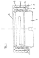
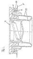
- Figure 1 shows a closure according to the invention with neck 1 and Screw lid 3, the neck 1 is a cuff-shaped Fastening device 4, which has an elevation 5a on the Opening of the container 5 is pressed. At the outer end of the cover 3 is a circumferentially bevelled sealing tab 6, which is extends to the upper bottom of the container 5 and after this moored outside.
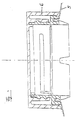
- Figure 2 shows an inventive device in the form of a Screw cap push-in closure with a chamfered area on the outer edge of the lid 3, from which the circumferential sealing tab 6 extends to the upper bottom of the container 5.
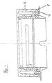
- Figure 3 shows an inventive device in the form of a Screw cap push-in closure, in which the circumferential sealing tab 6 rests on a conically shaped upper floor of the container 5.
- Figure 4 shows an inventive device in the form of a Screw cap push-in closure with a circumferential sealing flap 6, which are executed in their lower part twice or with a groove is provided, forming an inner sealing edge 7 and one outer sealing edge 8.
- Figure 5 is an inventive device in the form of a Screw cap push-in closure shown, the additional one Parental controls included. Is located on the circumferential sealing tab 6 at the level of the sleeve 4 facing inwards with a toothing 9 for example 2 to 5 teeth. This interlocking is also on the opposite side of the circumferential sealing tab 6 attached.
- the Cuff 4 of the neck also has serrations 10, which are are circumferentially on the outer part of the cuff 4. When screwing on of the cover 3, the sealing tab 6 slides with the toothing 9 over the Teeth 10 of the sleeve 4 of the lower part until the Capping is complete. 9 and 10 then interlock.
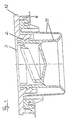
- Figure 6 shows an inventive device in the form of a Screw cap push-in closure with pressed-in bellows-like Lower part 11, which at its upper end with a screw thread 2 is provided.
- the screw cover 3 is located on this extreme edge of the screw cap 3 is in the direction of Sealing tab 6 a paragraph that can be used as a grip edge 12.
- the Sealing flap 6 is facing outward on the top of the container 5 on.
- Figure 7 is a closure according to the invention with the bellows pressed in 11 shown, the lid 3 on the circumferential sealing tab 6 in height the cuff-shaped fastening device 4 locking knobs 13 having.
- the cuff-shaped fastening device 4 comprises the Edge of the container 5 only partially, so that the locking knobs 13 Sealing tab 6 under the cuff-shaped fastening device 4 can snap into place when the closure device is pressed on.
Landscapes
- Engineering & Computer Science (AREA)
- Mechanical Engineering (AREA)
- Closures For Containers (AREA)
- Electrical Discharge Machining, Electrochemical Machining, And Combined Machining (AREA)
- Glass Compositions (AREA)
- Medical Preparation Storing Or Oral Administration Devices (AREA)
Claims (7)
- Dispositif destiné à la fermeture d'un récipient (5) comportant un fond supérieur de configuration horizontale ou conique, et comprenant un goulot (1) en forme d'embout, qui peut être fixé dans une ouverture du récipient sur le fond supérieur du récipient (5), et qui est doté à son extrémité supérieure d'un filetage de vissage (2) sur lequel peut être vissé un couvercle (3), caractérisé en ce que le couvercle (3) est pourvu sur toute la périphérie, sur une zone de diamètre supérieur au diamètre du goulot (1), d'une languette d'étanchéité (6), qui s'étend, dans le sens de son étendue longitudinale, en direction du fond supérieur du récipient (5), en vue de venir s'appuyer sur le fond supérieur du récipient (5) lorsque le couvercle (3) est vissé à fond sur le goulot.
- Dispositif selon la revendication 1, caractérisé en ce que la languette d'étanchéité (6) est conçue de façon à présenter des rainures au niveau de sa partie inférieure s'appuyant sur le fond supérieur du réservoir (5), ou de manière à être biseautée à cet endroit.
- Dispositif selon la revendication 1 ou 2, caractérisé en ce que la languette d'étanchéité (6) est de configuration flexible.
- Dispositif selon l'une des revendications 1 à 3, caractérisé en ce qu'il présente une sécurité-enfant usuelle.
- Dispositif selon l'une des revendications précédentes, caractérisé en ce que le goulot (1) en forme d'embout est d'une configuration flexible ou comporte des zones flexibles.
- Dispositif selon la revendication 5, caractérisé en ce que le goulot (1) est réalisé sous la forme d'un soufflet pouvant être enfoncé dans l'ouverture du récipient.
- Dispositif selon l'une des revendications précédentes, caractérisé en ce qu'il comporte, entre le filetage de vissage du couvercle (3) et sa languette d'étanchéité (6), un ou plusieurs dispositifs d'étanchéité, qui, lors de la mise en place du couvercle, s'engagent dans le système de fixation du goulot (1) sur le fond supérieur du récipient (5).
Applications Claiming Priority (3)
| Application Number | Priority Date | Filing Date | Title |
|---|---|---|---|
| DE29610125U | 1996-06-08 | ||
| DE29610125U DE29610125U1 (de) | 1996-06-08 | 1996-06-08 | Vorrichtung zum Verschließen von Behältern |
| PCT/EP1997/002908 WO1997047530A1 (fr) | 1996-06-08 | 1997-06-04 | Dispositif pour la fermeture de recipients |
Publications (2)
| Publication Number | Publication Date |
|---|---|
| EP0907577A1 EP0907577A1 (fr) | 1999-04-14 |
| EP0907577B1 true EP0907577B1 (fr) | 2002-04-03 |
Family
ID=8024954
Family Applications (1)
| Application Number | Title | Priority Date | Filing Date |
|---|---|---|---|
| EP97929148A Expired - Lifetime EP0907577B1 (fr) | 1996-06-08 | 1997-06-04 | Dispositif pour la fermeture de recipients |
Country Status (7)
| Country | Link |
|---|---|
| EP (1) | EP0907577B1 (fr) |
| AT (1) | ATE215482T1 (fr) |
| AU (1) | AU714986B2 (fr) |
| BR (1) | BR9709563A (fr) |
| CA (1) | CA2257573A1 (fr) |
| DE (2) | DE29610125U1 (fr) |
| WO (1) | WO1997047530A1 (fr) |
Families Citing this family (6)
| Publication number | Priority date | Publication date | Assignee | Title |
|---|---|---|---|---|
| DE19807768A1 (de) * | 1998-02-24 | 1999-08-26 | Bericap Gmbh & Co | Kunststoffdeckel mit Kunststoffverschluß |
| US20040045967A1 (en) * | 2002-09-11 | 2004-03-11 | Becker Gordon P. | Reclosable metal beverage can |
| BRPI0910624B1 (pt) | 2008-04-16 | 2019-07-02 | Guala Closures International B.V. | Tampa de fechamento inviolável compacta |
| USD747201S1 (en) | 2013-09-18 | 2016-01-12 | Bericap | Closure |
| FR3015442B1 (fr) | 2013-12-24 | 2016-02-05 | Bericap | Dispositif de bouchage articule avec indicateur de premiere ouverture |
| USD833278S1 (en) | 2014-09-03 | 2018-11-13 | Bericap | Closure for a container |
Family Cites Families (7)
| Publication number | Priority date | Publication date | Assignee | Title |
|---|---|---|---|---|
| US2818204A (en) * | 1956-01-27 | 1957-12-31 | Continental Can Co | Plastic nozzle and screw cap assembly |
| FR1516740A (fr) * | 1966-03-04 | 1968-02-05 | Chimex | Nouveau récipient pour matières pulvérulentes |
| GB1261362A (en) * | 1969-04-14 | 1972-01-26 | Charles Douglas Waller | Improvements in and relating to jars and other containers |
| DE2810726A1 (de) * | 1978-03-13 | 1979-09-27 | J W Remy & Geiser Kg | Vorrichtung zur abgabe von fluessigkeiten, pasten oder pulvern aus behaeltern |
| DE3545548A1 (de) * | 1985-12-21 | 1987-07-02 | Berg Jacob Gmbh Co Kg | Garantieverschluss |
| DE4209784C2 (de) * | 1992-03-26 | 1994-01-05 | Stolz Heinrich Gmbh | Verschluß für einen Behälter aus einem Verschlußunterteil und einer Schraubkappe |
| DE4329036C2 (de) * | 1993-08-30 | 1999-08-19 | Herberts Gmbh | Vorrichtung zum Verschließen von Behältern |
-
1996
- 1996-06-08 DE DE29610125U patent/DE29610125U1/de not_active Expired - Lifetime
-
1997
- 1997-06-04 AT AT97929148T patent/ATE215482T1/de not_active IP Right Cessation
- 1997-06-04 DE DE59706877T patent/DE59706877D1/de not_active Expired - Fee Related
- 1997-06-04 EP EP97929148A patent/EP0907577B1/fr not_active Expired - Lifetime
- 1997-06-04 BR BR9709563A patent/BR9709563A/pt active Search and Examination
- 1997-06-04 AU AU33369/97A patent/AU714986B2/en not_active Ceased
- 1997-06-04 WO PCT/EP1997/002908 patent/WO1997047530A1/fr not_active Ceased
- 1997-06-04 CA CA002257573A patent/CA2257573A1/fr not_active Abandoned
Also Published As
| Publication number | Publication date |
|---|---|
| DE59706877D1 (de) | 2002-05-08 |
| ATE215482T1 (de) | 2002-04-15 |
| WO1997047530A1 (fr) | 1997-12-18 |
| BR9709563A (pt) | 1999-08-10 |
| EP0907577A1 (fr) | 1999-04-14 |
| AU3336997A (en) | 1998-01-07 |
| DE29610125U1 (de) | 1996-08-29 |
| AU714986B2 (en) | 2000-01-13 |
| CA2257573A1 (fr) | 1997-12-18 |
Similar Documents
| Publication | Publication Date | Title |
|---|---|---|
| DE69303486T2 (de) | Mehrkammerspender zur lagerung und mischung des inhalts | |
| DE2828063C2 (de) | Kindersicherer Verschluß | |
| DE2600410A1 (de) | Sicherheitsverschluss und behaelter | |
| DE202021004459U1 (de) | Mehrkomponentenverschluss | |
| DE2056527A1 (de) | Vorrichtung, insbesondere Verschlußvor richtung fur Behalter, bestehend aus einer mit einem Behalterhals abdichtend und un verletzlich zusammenwirkenden Verschluß kappe aus elastomerem Material | |
| WO1995015892A1 (fr) | Fermeture demi-tour pour recipients | |
| DE3312632C2 (de) | Kindersicherer Verschluß | |
| CH683174A5 (de) | Kunststoffverschluss mit Garantieelement. | |
| DE1298931B (de) | Behaelter zur Aufnahme aetzender Fluessigkeiten | |
| EP0907577B1 (fr) | Dispositif pour la fermeture de recipients | |
| DE2724099C2 (fr) | ||
| DE2801277C2 (fr) | ||
| DE2249009A1 (de) | Sicherheitsverschluss | |
| EP0569897A1 (fr) | Dispositif de fermeture à l'épreuve des enfants pour récipients | |
| DE19851331A1 (de) | Verschlußkappe für Gewindehalsflaschen | |
| DE2024385C3 (de) | Sicherheitsverschluß für einen Behalter | |
| WO2021043720A1 (fr) | Fermeture de contenant | |
| DE4329036C2 (de) | Vorrichtung zum Verschließen von Behältern | |
| DE10034608A1 (de) | Schraubverschlußkappe aus Kunststoff | |
| DE10045887C2 (de) | Schraubverschluss für eine Zwei-Komponenten-Packung | |
| AT406575B (de) | Behälter | |
| EP0641724A1 (fr) | Dispositif de fermeture de récipients et récipient | |
| CH682227A5 (en) | Plastics bottle closure - has closure part fixed to bottle neck with lower securing strip preventing unauthorised removal from neck | |
| DE2504803C2 (de) | Vakuum-Verschluß für Behälter | |
| DE9317419U1 (de) | Vorrichtung zum Verschließen von Behältern, insbesondere von Dosen |
Legal Events
| Date | Code | Title | Description |
|---|---|---|---|
| PUAI | Public reference made under article 153(3) epc to a published international application that has entered the european phase |
Free format text: ORIGINAL CODE: 0009012 |
|
| 17P | Request for examination filed |
Effective date: 19981209 |
|
| AK | Designated contracting states |
Kind code of ref document: A1 Designated state(s): AT BE CH DE DK ES FR GB GR IE IT LI NL PT SE |
|
| 17Q | First examination report despatched |
Effective date: 19990420 |
|
| RAP1 | Party data changed (applicant data changed or rights of an application transferred) |
Owner name: E.I. DU PONT DE NEMOURS AND COMPANY |
|
| GRAG | Despatch of communication of intention to grant |
Free format text: ORIGINAL CODE: EPIDOS AGRA |
|
| GRAG | Despatch of communication of intention to grant |
Free format text: ORIGINAL CODE: EPIDOS AGRA |
|
| GRAH | Despatch of communication of intention to grant a patent |
Free format text: ORIGINAL CODE: EPIDOS IGRA |
|
| GRAH | Despatch of communication of intention to grant a patent |
Free format text: ORIGINAL CODE: EPIDOS IGRA |
|
| REG | Reference to a national code |
Ref country code: GB Ref legal event code: IF02 |
|
| GRAA | (expected) grant |
Free format text: ORIGINAL CODE: 0009210 |
|
| AK | Designated contracting states |
Kind code of ref document: B1 Designated state(s): AT BE CH DE DK ES FR GB GR IE IT LI NL PT SE |
|
| PG25 | Lapsed in a contracting state [announced via postgrant information from national office to epo] |
Ref country code: NL Free format text: LAPSE BECAUSE OF FAILURE TO SUBMIT A TRANSLATION OF THE DESCRIPTION OR TO PAY THE FEE WITHIN THE PRESCRIBED TIME-LIMIT Effective date: 20020403 Ref country code: IT Free format text: LAPSE BECAUSE OF FAILURE TO SUBMIT A TRANSLATION OF THE DESCRIPTION OR TO PAY THE FEE WITHIN THE PRE;WARNING: LAPSES OF ITALIAN PATENTS WITH EFFECTIVE DATE BEFORE 2007 MAY HAVE OCCURRED AT ANY TIME BEFORE 2007. THE CORRECT EFFECTIVE DATE MAY BE DIFFERENT FROM THE ONE RECORDED.SCRIBED TIME-LIMIT Effective date: 20020403 Ref country code: IE Free format text: LAPSE BECAUSE OF FAILURE TO SUBMIT A TRANSLATION OF THE DESCRIPTION OR TO PAY THE FEE WITHIN THE PRESCRIBED TIME-LIMIT Effective date: 20020403 Ref country code: GR Free format text: LAPSE BECAUSE OF FAILURE TO SUBMIT A TRANSLATION OF THE DESCRIPTION OR TO PAY THE FEE WITHIN THE PRESCRIBED TIME-LIMIT Effective date: 20020403 Ref country code: GB Free format text: LAPSE BECAUSE OF FAILURE TO SUBMIT A TRANSLATION OF THE DESCRIPTION OR TO PAY THE FEE WITHIN THE PRESCRIBED TIME-LIMIT Effective date: 20020403 Ref country code: FR Free format text: LAPSE BECAUSE OF FAILURE TO SUBMIT A TRANSLATION OF THE DESCRIPTION OR TO PAY THE FEE WITHIN THE PRESCRIBED TIME-LIMIT Effective date: 20020403 |
|
| REF | Corresponds to: |
Ref document number: 215482 Country of ref document: AT Date of ref document: 20020415 Kind code of ref document: T |
|
| REG | Reference to a national code |
Ref country code: CH Ref legal event code: EP |
|
| REF | Corresponds to: |
Ref document number: 59706877 Country of ref document: DE Date of ref document: 20020508 |
|
| REG | Reference to a national code |
Ref country code: IE Ref legal event code: FG4D Free format text: GERMAN |
|
| PG25 | Lapsed in a contracting state [announced via postgrant information from national office to epo] |
Ref country code: AT Free format text: LAPSE BECAUSE OF NON-PAYMENT OF DUE FEES Effective date: 20020604 |
|
| PG25 | Lapsed in a contracting state [announced via postgrant information from national office to epo] |
Ref country code: LI Free format text: LAPSE BECAUSE OF NON-PAYMENT OF DUE FEES Effective date: 20020630 Ref country code: CH Free format text: LAPSE BECAUSE OF NON-PAYMENT OF DUE FEES Effective date: 20020630 Ref country code: BE Free format text: LAPSE BECAUSE OF NON-PAYMENT OF DUE FEES Effective date: 20020630 |
|
| PG25 | Lapsed in a contracting state [announced via postgrant information from national office to epo] |
Ref country code: SE Free format text: LAPSE BECAUSE OF FAILURE TO SUBMIT A TRANSLATION OF THE DESCRIPTION OR TO PAY THE FEE WITHIN THE PRESCRIBED TIME-LIMIT Effective date: 20020703 Ref country code: PT Free format text: LAPSE BECAUSE OF FAILURE TO SUBMIT A TRANSLATION OF THE DESCRIPTION OR TO PAY THE FEE WITHIN THE PRESCRIBED TIME-LIMIT Effective date: 20020703 Ref country code: DK Free format text: LAPSE BECAUSE OF FAILURE TO SUBMIT A TRANSLATION OF THE DESCRIPTION OR TO PAY THE FEE WITHIN THE PRESCRIBED TIME-LIMIT Effective date: 20020703 |
|
| NLV1 | Nl: lapsed or annulled due to failure to fulfill the requirements of art. 29p and 29m of the patents act | ||
| GBV | Gb: ep patent (uk) treated as always having been void in accordance with gb section 77(7)/1977 [no translation filed] |
Effective date: 20020403 |
|
| PG25 | Lapsed in a contracting state [announced via postgrant information from national office to epo] |
Ref country code: ES Free format text: LAPSE BECAUSE OF FAILURE TO SUBMIT A TRANSLATION OF THE DESCRIPTION OR TO PAY THE FEE WITHIN THE PRESCRIBED TIME-LIMIT Effective date: 20021030 |
|
| REG | Reference to a national code |
Ref country code: IE Ref legal event code: FD4D Ref document number: 0907577E Country of ref document: IE |
|
| BERE | Be: lapsed |
Owner name: E.I. *DU PONT DE NEMOURS AND CY Effective date: 20020630 |
|
| EN | Fr: translation not filed | ||
| PLBE | No opposition filed within time limit |
Free format text: ORIGINAL CODE: 0009261 |
|
| STAA | Information on the status of an ep patent application or granted ep patent |
Free format text: STATUS: NO OPPOSITION FILED WITHIN TIME LIMIT |
|
| REG | Reference to a national code |
Ref country code: CH Ref legal event code: PL |
|
| 26N | No opposition filed |
Effective date: 20030106 |
|
| PGFP | Annual fee paid to national office [announced via postgrant information from national office to epo] |
Ref country code: DE Payment date: 20050819 Year of fee payment: 9 |
|
| PG25 | Lapsed in a contracting state [announced via postgrant information from national office to epo] |
Ref country code: DE Free format text: LAPSE BECAUSE OF NON-PAYMENT OF DUE FEES Effective date: 20070103 |