EP0907525B1 - Boite de vitesses couplable sous charge pour vehicules automobiles - Google Patents
Boite de vitesses couplable sous charge pour vehicules automobiles Download PDFInfo
- Publication number
- EP0907525B1 EP0907525B1 EP97929220A EP97929220A EP0907525B1 EP 0907525 B1 EP0907525 B1 EP 0907525B1 EP 97929220 A EP97929220 A EP 97929220A EP 97929220 A EP97929220 A EP 97929220A EP 0907525 B1 EP0907525 B1 EP 0907525B1
- Authority
- EP
- European Patent Office
- Prior art keywords
- shift transmission
- power shift
- clutch
- transmission according
- brake
- Prior art date
- Legal status (The legal status is an assumption and is not a legal conclusion. Google has not performed a legal analysis and makes no representation as to the accuracy of the status listed.)
- Expired - Lifetime
Links
- 230000005540 biological transmission Effects 0.000 title claims abstract description 50
- 238000005096 rolling process Methods 0.000 claims abstract description 11
- 230000000694 effects Effects 0.000 claims description 4
- 238000011144 upstream manufacturing Methods 0.000 claims description 4
- 239000007858 starting material Substances 0.000 claims 3
- 230000001105 regulatory effect Effects 0.000 abstract description 5
- 208000012886 Vertigo Diseases 0.000 description 7
- 230000003213 activating effect Effects 0.000 description 3
- 239000002655 kraft paper Substances 0.000 description 3
- 230000008878 coupling Effects 0.000 description 2
- 238000010168 coupling process Methods 0.000 description 2
- 238000005859 coupling reaction Methods 0.000 description 2
- 230000008646 thermal stress Effects 0.000 description 2
- 241001295925 Gegenes Species 0.000 description 1
- 230000001133 acceleration Effects 0.000 description 1
- 230000017525 heat dissipation Effects 0.000 description 1
- 238000005259 measurement Methods 0.000 description 1
- 230000035882 stress Effects 0.000 description 1
Images
Classifications
-
- B—PERFORMING OPERATIONS; TRANSPORTING
- B60—VEHICLES IN GENERAL
- B60T—VEHICLE BRAKE CONTROL SYSTEMS OR PARTS THEREOF; BRAKE CONTROL SYSTEMS OR PARTS THEREOF, IN GENERAL; ARRANGEMENT OF BRAKING ELEMENTS ON VEHICLES IN GENERAL; PORTABLE DEVICES FOR PREVENTING UNWANTED MOVEMENT OF VEHICLES; VEHICLE MODIFICATIONS TO FACILITATE COOLING OF BRAKES
- B60T7/00—Brake-action initiating means
- B60T7/12—Brake-action initiating means for automatic initiation; for initiation not subject to will of driver or passenger
- B60T7/122—Brake-action initiating means for automatic initiation; for initiation not subject to will of driver or passenger for locking of reverse movement
-
- B—PERFORMING OPERATIONS; TRANSPORTING
- B60—VEHICLES IN GENERAL
- B60W—CONJOINT CONTROL OF VEHICLE SUB-UNITS OF DIFFERENT TYPE OR DIFFERENT FUNCTION; CONTROL SYSTEMS SPECIALLY ADAPTED FOR HYBRID VEHICLES; ROAD VEHICLE DRIVE CONTROL SYSTEMS FOR PURPOSES NOT RELATED TO THE CONTROL OF A PARTICULAR SUB-UNIT
- B60W10/00—Conjoint control of vehicle sub-units of different type or different function
- B60W10/02—Conjoint control of vehicle sub-units of different type or different function including control of driveline clutches
-
- B—PERFORMING OPERATIONS; TRANSPORTING
- B60—VEHICLES IN GENERAL
- B60W—CONJOINT CONTROL OF VEHICLE SUB-UNITS OF DIFFERENT TYPE OR DIFFERENT FUNCTION; CONTROL SYSTEMS SPECIALLY ADAPTED FOR HYBRID VEHICLES; ROAD VEHICLE DRIVE CONTROL SYSTEMS FOR PURPOSES NOT RELATED TO THE CONTROL OF A PARTICULAR SUB-UNIT
- B60W10/00—Conjoint control of vehicle sub-units of different type or different function
- B60W10/10—Conjoint control of vehicle sub-units of different type or different function including control of change-speed gearings
- B60W10/11—Stepped gearings
- B60W10/115—Stepped gearings with planetary gears
-
- B—PERFORMING OPERATIONS; TRANSPORTING
- B60—VEHICLES IN GENERAL
- B60W—CONJOINT CONTROL OF VEHICLE SUB-UNITS OF DIFFERENT TYPE OR DIFFERENT FUNCTION; CONTROL SYSTEMS SPECIALLY ADAPTED FOR HYBRID VEHICLES; ROAD VEHICLE DRIVE CONTROL SYSTEMS FOR PURPOSES NOT RELATED TO THE CONTROL OF A PARTICULAR SUB-UNIT
- B60W30/00—Purposes of road vehicle drive control systems not related to the control of a particular sub-unit, e.g. of systems using conjoint control of vehicle sub-units
- B60W30/18—Propelling the vehicle
-
- B—PERFORMING OPERATIONS; TRANSPORTING
- B60—VEHICLES IN GENERAL
- B60W—CONJOINT CONTROL OF VEHICLE SUB-UNITS OF DIFFERENT TYPE OR DIFFERENT FUNCTION; CONTROL SYSTEMS SPECIALLY ADAPTED FOR HYBRID VEHICLES; ROAD VEHICLE DRIVE CONTROL SYSTEMS FOR PURPOSES NOT RELATED TO THE CONTROL OF A PARTICULAR SUB-UNIT
- B60W2510/00—Input parameters relating to a particular sub-units
- B60W2510/10—Change speed gearings
- B60W2510/105—Output torque
-
- B—PERFORMING OPERATIONS; TRANSPORTING
- B60—VEHICLES IN GENERAL
- B60W—CONJOINT CONTROL OF VEHICLE SUB-UNITS OF DIFFERENT TYPE OR DIFFERENT FUNCTION; CONTROL SYSTEMS SPECIALLY ADAPTED FOR HYBRID VEHICLES; ROAD VEHICLE DRIVE CONTROL SYSTEMS FOR PURPOSES NOT RELATED TO THE CONTROL OF A PARTICULAR SUB-UNIT
- B60W2710/00—Output or target parameters relating to a particular sub-units
- B60W2710/10—Change speed gearings
- B60W2710/1005—Transmission ratio engaged
-
- B—PERFORMING OPERATIONS; TRANSPORTING
- B60—VEHICLES IN GENERAL
- B60W—CONJOINT CONTROL OF VEHICLE SUB-UNITS OF DIFFERENT TYPE OR DIFFERENT FUNCTION; CONTROL SYSTEMS SPECIALLY ADAPTED FOR HYBRID VEHICLES; ROAD VEHICLE DRIVE CONTROL SYSTEMS FOR PURPOSES NOT RELATED TO THE CONTROL OF A PARTICULAR SUB-UNIT
- B60W2710/00—Output or target parameters relating to a particular sub-units
- B60W2710/18—Braking system
Definitions
- the invention relates to a powershift transmission for motor vehicles and mobile machines.
- Powershift transmissions are generally hydrodynamic Converter as starting device. These converters claim lots of space and have a loss of performance through flow or splash losses. To the gear length to shorten and avoid this loss of performance in a special form of that in the European Patent specification 0 214 989 B2 described invention of Converter left out. Its function as a starting element takes over a gear brake. This brake becomes strong claimed.
- the invention is based on the object starting from EP-A 517 420 a powershift transmission with a compact, inexpensive and low-wear starting device from to create high durability and high efficiency, whereby rolling away against the direction of travel is avoided.
- the clutch load must be kept low become.
- the clutch should only be as short as possible Slips operate to their thermal stress to keep low. In any case, the vehicle should be on the mountain do not have to be held with the clutch.
- the powershift transmission has the said lock to prevent the vehicle from rolling away the direction of travel intended by the gear selection prevented.
- a clutch is in powershift transmissions is there anyway. This as a starting device serving clutch only needs to be a little stronger be dimensioned.
- the scheme ensures that the clutch is thermally stressed as little as possible and is worn out. Length and weight of the powershift transmission are significantly reduced with this solution because of hydrodynamic converter is omitted and no separate upstream Clutch is required.
- This clutch is preferably regulated Multi-plate clutch designed.
- the lock is designed as a freewheel, in particular as Clamp body freewheel or ratchet freewheel.
- the freewheel is preferably on the drive shaft the powershift transmission, d. H. on the gearbox facing Side of the multi-plate clutch, especially in the area the multi-plate clutch attached.
- an unintended one can be used as an alternative to the invention Roll away against the direction of travel by a electronic circuit that acts on switching elements be prevented.
- One possibility is with one unintentionally rolling away to activate the service brake.
- the brake system with the transmission system must be used be coordinated.
- Another Alternative of the invention is that Lock in the gearbox in connection with the starting clutch as Completed system, designed as a gear brake.
- the braking effect is achieved in that Gearbox a switching element combination is set which blocks the transmission output.
- the electronic Control of this transmission brake advantageous as Overlap control is done, d. H. if the starting clutch starts to engage when engaging, the Braking effect of a switching element withdrawn to the extent in which the starting clutch takes up torque.
- the slope downforce can be with known vehicle mass be determined based on their effect on the vehicle, d. H. based on the acceleration of the vehicle during a very short measuring time, within which the vehicle is hardly noticeable rolled away. This requires measuring the angular velocity the transmission output shaft and a force calculation from the angular velocity change.
- This can be the slope downforce of the vehicle based on a measurement of the resulting torque the transmission output shaft can be determined.
- the Slope downforce with known vehicle mass by means of a Inclination sensor determined.
- the slope downforce is advantageous in the known Vehicle mass over the gradient of the transmission output speed determined.
- the multi-plate clutch is advantageous as a wet clutch trained to achieve good heat dissipation.
- One of the essential alternatives of the invention is the regulated transmission brake as compact, inexpensive and low-wear starting device, wherein an overlap circuit the rolling away of the motor vehicle contrary to the one intended by the gear selection Direction of travel prevented by activating the service brake.
- This is advantageous in so far as a gear brake is already present in powershift transmissions.
- This as The gear brake used for starting device only has to be dimensioned somewhat stronger.
- the scheme ensures that the transmission brake thermal as little as possible is strained and worn. Length and weight of the powershift transmission are significantly reduced with this solution, since the hydrodynamic converter is eliminated and none own upstream coupling is required.
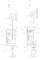
- a motor 1 drives as a wet multi-plate clutch trained starting clutch 2 and a powershift transmission 3 and a subordinate differential gear 4 Vehicle.
- FIG. 2 In the embodiment of the invention shown in FIG. 2 prevents a mechanical freewheel 3.1 between Gearbox drive shaft 3.2 and gearbox housing 3.3 are twisted this shaft against the direction of motor rotation. This due to 3 forward gears engaged in the powershift transmission a rollback lock and when reverse gear is engaged a roll-away lock to the front, d. H. in both cases a lock against unintentional rolling away of the motor vehicle contrary to the one intended by the gear selection Direction of travel.
- the starting clutch 2 is omitted from FIG. 1.
- the coupling B is more dimensioned for this and serves as a starting clutch. It is closed in order to start, the first gear is shifted.
- clutch C is closed in a controlled manner. This The clutch is also more powerful than the starting clutch. Starting in reverse is not, however as often as the forward start, so the request not so high in terms of wear on clutch C. are like those on clutch B.
- a regulated transmission brake serves as a starting device and an overlap circuit prevents the motor vehicle from rolling away against the direction of travel intended by the gear selection by activating the service brake
- the starting clutch 2 is released away from Fig. 1.
- the brake E is dimensioned stronger for this and serves as a starting clutch.
- Clutch B is closed for starting in first gear.
- the service brakes are braked so that the vehicle cannot roll away.
- the planet carrier 3.10 can rotate freely and therefore does not transmit any torque to the ring gear 3.8.
- the planet gear 3.6 which is in engagement with the ring gear 3.8, rolls on the latter.
- the brake E is now closed in a controlled manner, and the service brake is released to the extent that the planet carrier takes up torque.
- Clutch C is closed for starting in reverse gear.
- the vehicle starts off in the same way as above:
- the service brakes are braked so that the vehicle cannot roll away.
- the brake E is open, the planet carrier 3.10 can rotate freely and therefore does not transmit any torque to the ring gear 3.8.
- the planet gear 3.6 which is in engagement with the ring gear 3.8, rolls on the latter.
- the brake E is now closed in a controlled manner, and the service brake is released to the extent that the planet carrier takes up torque.
Landscapes
- Engineering & Computer Science (AREA)
- Transportation (AREA)
- Mechanical Engineering (AREA)
- Chemical & Material Sciences (AREA)
- Combustion & Propulsion (AREA)
- Automation & Control Theory (AREA)
- Structure Of Transmissions (AREA)
- Arrangement Of Transmissions (AREA)
- Control Of Transmission Device (AREA)
Abstract
Claims (13)
- Boíte de vitesses commandée sous charge pour véhicules automobiles avec un dispositif de démarrage amont qui est réalisé sous la forme d'un embrayage de démarrage (2) amont, sous la forme d'un embrayage de changement de vitesses, sous la forme d'un embrayage à disques réglé ou sous la forme d'un frein à engrenage,
caractérisée en ce qu'un blocage est prévu pour empêcher que le véhicule roule dans le sens opposé à la direction de marche voulu par le choix de la vitesse enclenchée, en ce que le blocage est réalisé comme roue libre (3.1) ou comme blocage à réglage électronique ou comme frein à engrenage. - Boíte de vitesses commandée sous charge selon la revendication 1, caractérisée en ce que la roue libre (3.1) servant de blocage agit sur un arbre qui tourne en marche avant et en marche arrière avec un entraínement par la machine motrice toujours dans le même sens et empêche l'arbre de tourner dans le sens inverse lorsque l'entraínement est interrompu.
- Boíte de vitesses commandée sous charge selon la revendication 1 ou 2, caractérisée en ce que la roue libre (3.1) est réalisée sous la forme d'une roue libre à dispositif à serrage ou d'une roue libre à cliquet.
- Boíte de vitesses commandée sous charge selon l'une des revendications précédentes, caractérisée en ce que la roue libre (3.1) est montée sur l'arbre menant de la boíte de vitesses commandée sous charge (3), notamment dans la zone de l'embrayage à disques.
- Boíte de vitesses commandée sous charge selon la revendication 1, caractérisée en ce que le blocage à réglage électronique agit par l'activation du frein de service.
- Boíte de vitesses commandée sous charge selon l'une des revendications précédentes, caractérisée en ce que le frein de service agit sur un ou plusieurs éléments de construction d'un engrenage planétaire.
- Boíte de vitesses commandée sous charge selon l'une des revendications précédentes, caractérisée en ce que le frein de service et l'embrayage de démarrage (2) de la boíte de vitesses commandée sous charge (3) sont réglés par une commande à recoupement.
- Boíte de vitesses commandée sous charge selon la revendication 7, caractérisée en ce que la commande à recoupement est réglée en fonction de la force descensionnelle en pente.
- Boíte de vitesses commandée sous charge selon la revendication 8, caractérisée en ce que la force descensionnelle en pente est calculée à partir de son effet sur l'arbre mené (3.9) de la boíte de vitesses.
- Boíte de vitesses commandée sous charge selon la revendication 8, caractérisée en ce que la force descensionnelle en pente est déterminée au moyen d'un détecteur de force ou d'un détecteur de couple.
- Boíte de vitesses commandée sous charge selon la revendication 8, caractérisée en ce que la force descensionnelle en pente est déterminée au moyen d'un détecteur d'inclinaison.
- Boíte de vitesses commandée sous charge selon la revendication 8, caractérisée en ce que la force descensionnelle en pente est déterminée au moyen du gradient de la vitesse de sortie de la boíte de vitesses.
- Boíte de vitesses commandée sous charge selon l'une des revendications précédentes, caractérisée en ce que l'embrayage à disques est réalisé sous la forme d'un embrayage humide.
Applications Claiming Priority (3)
| Application Number | Priority Date | Filing Date | Title |
|---|---|---|---|
| DE19625355 | 1996-06-25 | ||
| DE19625355A DE19625355A1 (de) | 1996-06-25 | 1996-06-25 | Lastschaltgetriebe für Kraftfahrzeuge |
| PCT/EP1997/003198 WO1997049573A1 (fr) | 1996-06-25 | 1997-06-19 | Boite de vitesses couplable sous charge pour vehicules automobiles |
Publications (2)
| Publication Number | Publication Date |
|---|---|
| EP0907525A1 EP0907525A1 (fr) | 1999-04-14 |
| EP0907525B1 true EP0907525B1 (fr) | 2000-03-22 |
Family
ID=7797936
Family Applications (1)
| Application Number | Title | Priority Date | Filing Date |
|---|---|---|---|
| EP97929220A Expired - Lifetime EP0907525B1 (fr) | 1996-06-25 | 1997-06-19 | Boite de vitesses couplable sous charge pour vehicules automobiles |
Country Status (5)
| Country | Link |
|---|---|
| US (1) | US6244402B1 (fr) |
| EP (1) | EP0907525B1 (fr) |
| JP (1) | JP2000512591A (fr) |
| DE (2) | DE19625355A1 (fr) |
| WO (1) | WO1997049573A1 (fr) |
Families Citing this family (13)
| Publication number | Priority date | Publication date | Assignee | Title |
|---|---|---|---|---|
| DE19921200A1 (de) * | 1999-05-07 | 2000-11-09 | Bayerische Motoren Werke Ag | Wegrollsicherung für Kraftfahrzeuge |
| DE19932613A1 (de) * | 1999-07-13 | 2001-01-18 | Zahnradfabrik Friedrichshafen | Automatgetriebe |
| DE19949856A1 (de) * | 1999-10-15 | 2001-04-19 | Zahnradfabrik Friedrichshafen | Schaltgetriebe |
| SE0004715D0 (sv) * | 2000-12-20 | 2000-12-20 | Haldex Brake Prod Ab | A transmission brake |
| US7066304B2 (en) | 1999-12-02 | 2006-06-27 | Haldex Brake Products Ab | Disc brake |
| DE10135744A1 (de) * | 2001-07-21 | 2003-02-06 | Zahnradfabrik Friedrichshafen | Vermeidung des Rückrollens eines Fahrzeuges |
| US6827664B2 (en) * | 2001-11-15 | 2004-12-07 | General Motors Corporation | Transmission |
| DE10161815A1 (de) | 2001-12-14 | 2003-06-26 | Borgwarner Inc | Einrichtung zum Anfahren eines mit einer Automatikgetriebeanordnung ausgestatteten Kraftfahrzeugs |
| US7357754B2 (en) * | 2005-07-22 | 2008-04-15 | Gm Global Technology Operations, Inc. | Mechanism and method of controlling an automatic shifting power transmission to effect a first gear launch |
| DE102007044683B4 (de) | 2007-09-19 | 2018-06-07 | Dr. Ing. H.C. F. Porsche Aktiengesellschaft | Doppelkupplungsgetriebe mit Freilauf |
| JP4922224B2 (ja) * | 2008-03-27 | 2012-04-25 | 正博 大窪 | 多段自動変速機 |
| WO2011032200A1 (fr) * | 2009-09-21 | 2011-03-24 | Nt Consulting International Pty Limited | Transmission à aide au démarrage en côte |
| DE102017111768A1 (de) * | 2017-05-30 | 2018-12-06 | Schaeffler Technologies AG & Co. KG | Getriebeausgangsanordnung |
Family Cites Families (13)
| Publication number | Priority date | Publication date | Assignee | Title |
|---|---|---|---|---|
| DE2003977A1 (de) * | 1970-01-29 | 1971-08-19 | Werner Schlosser | Rueckrollsperre fuer Fahrzeuge aller Art |
| US4487303A (en) | 1982-12-27 | 1984-12-11 | Ford Motor Company | Automatic transmission start-up clutch control system |
| ZA853198B (en) * | 1984-05-26 | 1985-12-24 | Zahnradfabrik Friedrichshafen | Epicyclic gear unit |
| JPS6199747A (ja) * | 1984-10-19 | 1986-05-17 | Nissan Motor Co Ltd | 自動変速機のクリ−プトルク制御装置 |
| DE3621076A1 (de) * | 1986-06-24 | 1988-01-14 | Opel Adam Ag | Bremsvorrichtung fuer fahrzeuge mit anfahrhilfevorrichtung |
| DE3813516A1 (de) * | 1988-04-22 | 1989-11-02 | Bayerische Motoren Werke Ag | Getriebeaggregat fuer kraftfahrzeuge |
| US4867291A (en) * | 1988-06-28 | 1989-09-19 | Dana Corporation | Vehicle transmission hill holder with releasable one way clutch |
| US4968368A (en) | 1989-08-11 | 1990-11-06 | Steelastic West, Inc. | Method and apparatus for lining vessels |
| EP0716250B1 (fr) | 1991-06-03 | 1999-11-17 | New Holland U.K. Limited | Système de commande d'une transmission avec logique pour empêcher des changements de vitesse intempestifs lors d'un changement d'intention du conducteur |
| JP2878964B2 (ja) | 1994-05-02 | 1999-04-05 | アイシン・エィ・ダブリュ株式会社 | 自動変速機の制御方法及び制御装置 |
| US5474164A (en) | 1994-05-09 | 1995-12-12 | Ford Motor Company | Vehicle transmission hill holder |
| DE4442991A1 (de) * | 1994-12-02 | 1996-06-05 | Zahnradfabrik Friedrichshafen | Automatisches Getriebe |
| DE19546707A1 (de) * | 1995-12-14 | 1997-06-19 | Bayerische Motoren Werke Ag | Antriebseinrichtung für ein Kraftfahrzeug |
-
1996
- 1996-06-25 DE DE19625355A patent/DE19625355A1/de not_active Withdrawn
-
1997
- 1997-06-19 WO PCT/EP1997/003198 patent/WO1997049573A1/fr not_active Ceased
- 1997-06-19 EP EP97929220A patent/EP0907525B1/fr not_active Expired - Lifetime
- 1997-06-19 JP JP10502286A patent/JP2000512591A/ja active Pending
- 1997-06-19 US US09/202,262 patent/US6244402B1/en not_active Expired - Lifetime
- 1997-06-19 DE DE59701324T patent/DE59701324D1/de not_active Expired - Lifetime
Also Published As
| Publication number | Publication date |
|---|---|
| DE19625355A1 (de) | 1998-01-02 |
| US6244402B1 (en) | 2001-06-12 |
| EP0907525A1 (fr) | 1999-04-14 |
| JP2000512591A (ja) | 2000-09-26 |
| WO1997049573A1 (fr) | 1997-12-31 |
| DE59701324D1 (de) | 2000-04-27 |
Similar Documents
| Publication | Publication Date | Title |
|---|---|---|
| DE3935570C2 (de) | Gangwechselgetriebe für Kraftfahrzeuge | |
| EP0907525B1 (fr) | Boite de vitesses couplable sous charge pour vehicules automobiles | |
| DE102019114139B3 (de) | Kraftfahrzeuggetriebe | |
| DE10033476B9 (de) | Antriebsstrang eines Automatikgetriebes | |
| DE10307789A1 (de) | Automatikgetriebe | |
| DE69503691T2 (de) | Mehrgängiges Getriebe mit parallelen Achsen | |
| DE19530486A1 (de) | Automatikgetriebe-Kraftübertragungsstrang für ein Fahrzeug | |
| DE3906251A1 (de) | Hydraulische steuervorrichtung fuer ein automatisches getriebe | |
| DE19536952C2 (de) | Hydrodynamischer Drehmomentwandler mit Überbrückungskupplung | |
| DE2937366A1 (de) | Getriebe | |
| DE3919174C2 (fr) | ||
| DE3812623A1 (de) | Automatikgetriebe | |
| DE2038600C2 (de) | Gangwechselgetriebe für Fahrzeuge | |
| DE4313167C2 (de) | Unter Last schaltbares Getriebe | |
| EP1080321A1 (fr) | Transmission bimodale a plusieurs vitesses hydrodynamique et mecanique | |
| WO2008019778A1 (fr) | Boîte de vitesses automatique | |
| DE19961820A1 (de) | Antriebsstrang eines automatischen Getriebes | |
| DE102004060642B4 (de) | Steuerungsvorrichtung für ein Lastschaltgetriebe | |
| DE4328889C1 (de) | Planetenrädergetriebe für den Antrieb eines Fahrzeuges | |
| DE3740781C1 (de) | Anordnung zum selbsttaetigen Schalten eines Planetenraeder-Gangwechselgetriebes eines Kraftfahrzeuges | |
| EP1342660B1 (fr) | Système de contrôle pour des embrayages, notamment pour moyeu de bicyclette | |
| DE3407160C2 (de) | Planetenräder-Gangwechselgetriebe mit einem als Schnellgang ausgelegten Vorwärtsgang | |
| DE102007044683B4 (de) | Doppelkupplungsgetriebe mit Freilauf | |
| EP1565677A1 (fr) | Unite de transmission de puissance | |
| DE720797C (de) | Viergang-Umlaufraedergetriebe fuer Kraftfahrzeuge |
Legal Events
| Date | Code | Title | Description |
|---|---|---|---|
| PUAI | Public reference made under article 153(3) epc to a published international application that has entered the european phase |
Free format text: ORIGINAL CODE: 0009012 |
|
| 17P | Request for examination filed |
Effective date: 19980917 |
|
| AK | Designated contracting states |
Kind code of ref document: A1 Designated state(s): DE FR GB IT |
|
| GRAG | Despatch of communication of intention to grant |
Free format text: ORIGINAL CODE: EPIDOS AGRA |
|
| 17Q | First examination report despatched |
Effective date: 19990511 |
|
| GRAG | Despatch of communication of intention to grant |
Free format text: ORIGINAL CODE: EPIDOS AGRA |
|
| GRAH | Despatch of communication of intention to grant a patent |
Free format text: ORIGINAL CODE: EPIDOS IGRA |
|
| ITF | It: translation for a ep patent filed | ||
| GRAH | Despatch of communication of intention to grant a patent |
Free format text: ORIGINAL CODE: EPIDOS IGRA |
|
| GRAA | (expected) grant |
Free format text: ORIGINAL CODE: 0009210 |
|
| AK | Designated contracting states |
Kind code of ref document: B1 Designated state(s): DE FR GB IT |
|
| GBT | Gb: translation of ep patent filed (gb section 77(6)(a)/1977) |
Effective date: 20000322 |
|
| REF | Corresponds to: |
Ref document number: 59701324 Country of ref document: DE Date of ref document: 20000427 |
|
| ET | Fr: translation filed | ||
| PLBE | No opposition filed within time limit |
Free format text: ORIGINAL CODE: 0009261 |
|
| STAA | Information on the status of an ep patent application or granted ep patent |
Free format text: STATUS: NO OPPOSITION FILED WITHIN TIME LIMIT |
|
| 26N | No opposition filed | ||
| REG | Reference to a national code |
Ref country code: GB Ref legal event code: IF02 |
|
| PGFP | Annual fee paid to national office [announced via postgrant information from national office to epo] |
Ref country code: IT Payment date: 20060630 Year of fee payment: 10 |
|
| PG25 | Lapsed in a contracting state [announced via postgrant information from national office to epo] |
Ref country code: IT Free format text: LAPSE BECAUSE OF NON-PAYMENT OF DUE FEES Effective date: 20070619 |
|
| PGFP | Annual fee paid to national office [announced via postgrant information from national office to epo] |
Ref country code: FR Payment date: 20100709 Year of fee payment: 14 |
|
| PGFP | Annual fee paid to national office [announced via postgrant information from national office to epo] |
Ref country code: GB Payment date: 20100616 Year of fee payment: 14 |
|
| GBPC | Gb: european patent ceased through non-payment of renewal fee |
Effective date: 20110619 |
|
| REG | Reference to a national code |
Ref country code: FR Ref legal event code: ST Effective date: 20120229 |
|
| PG25 | Lapsed in a contracting state [announced via postgrant information from national office to epo] |
Ref country code: FR Free format text: LAPSE BECAUSE OF NON-PAYMENT OF DUE FEES Effective date: 20110630 |
|
| PG25 | Lapsed in a contracting state [announced via postgrant information from national office to epo] |
Ref country code: GB Free format text: LAPSE BECAUSE OF NON-PAYMENT OF DUE FEES Effective date: 20110619 |
|
| PGFP | Annual fee paid to national office [announced via postgrant information from national office to epo] |
Ref country code: DE Payment date: 20130612 Year of fee payment: 17 |
|
| REG | Reference to a national code |
Ref country code: DE Ref legal event code: R119 Ref document number: 59701324 Country of ref document: DE |
|
| PG25 | Lapsed in a contracting state [announced via postgrant information from national office to epo] |
Ref country code: DE Free format text: LAPSE BECAUSE OF NON-PAYMENT OF DUE FEES Effective date: 20150101 |
|
| REG | Reference to a national code |
Ref country code: DE Ref legal event code: R079 Ref document number: 59701324 Country of ref document: DE Free format text: PREVIOUS MAIN CLASS: B60K0041220000 Ipc: B60W0010020000 |