EP0907525B1 - Power shift transmission for motor vehicles - Google Patents
Power shift transmission for motor vehicles Download PDFInfo
- Publication number
- EP0907525B1 EP0907525B1 EP97929220A EP97929220A EP0907525B1 EP 0907525 B1 EP0907525 B1 EP 0907525B1 EP 97929220 A EP97929220 A EP 97929220A EP 97929220 A EP97929220 A EP 97929220A EP 0907525 B1 EP0907525 B1 EP 0907525B1
- Authority
- EP
- European Patent Office
- Prior art keywords
- shift transmission
- power shift
- clutch
- transmission according
- brake
- Prior art date
- Legal status (The legal status is an assumption and is not a legal conclusion. Google has not performed a legal analysis and makes no representation as to the accuracy of the status listed.)
- Expired - Lifetime
Links
- 230000005540 biological transmission Effects 0.000 title claims abstract description 50
- 238000005096 rolling process Methods 0.000 claims abstract description 11
- 230000000694 effects Effects 0.000 claims description 4
- 238000011144 upstream manufacturing Methods 0.000 claims description 4
- 239000007858 starting material Substances 0.000 claims 3
- 230000001105 regulatory effect Effects 0.000 abstract description 5
- 208000012886 Vertigo Diseases 0.000 description 7
- 230000003213 activating effect Effects 0.000 description 3
- 239000002655 kraft paper Substances 0.000 description 3
- 230000008878 coupling Effects 0.000 description 2
- 238000010168 coupling process Methods 0.000 description 2
- 238000005859 coupling reaction Methods 0.000 description 2
- 230000008646 thermal stress Effects 0.000 description 2
- 241001295925 Gegenes Species 0.000 description 1
- 230000001133 acceleration Effects 0.000 description 1
- 230000017525 heat dissipation Effects 0.000 description 1
- 238000005259 measurement Methods 0.000 description 1
- 230000035882 stress Effects 0.000 description 1
Images
Classifications
-
- B—PERFORMING OPERATIONS; TRANSPORTING
- B60—VEHICLES IN GENERAL
- B60T—VEHICLE BRAKE CONTROL SYSTEMS OR PARTS THEREOF; BRAKE CONTROL SYSTEMS OR PARTS THEREOF, IN GENERAL; ARRANGEMENT OF BRAKING ELEMENTS ON VEHICLES IN GENERAL; PORTABLE DEVICES FOR PREVENTING UNWANTED MOVEMENT OF VEHICLES; VEHICLE MODIFICATIONS TO FACILITATE COOLING OF BRAKES
- B60T7/00—Brake-action initiating means
- B60T7/12—Brake-action initiating means for automatic initiation; for initiation not subject to will of driver or passenger
- B60T7/122—Brake-action initiating means for automatic initiation; for initiation not subject to will of driver or passenger for locking of reverse movement
-
- B—PERFORMING OPERATIONS; TRANSPORTING
- B60—VEHICLES IN GENERAL
- B60W—CONJOINT CONTROL OF VEHICLE SUB-UNITS OF DIFFERENT TYPE OR DIFFERENT FUNCTION; CONTROL SYSTEMS SPECIALLY ADAPTED FOR HYBRID VEHICLES; ROAD VEHICLE DRIVE CONTROL SYSTEMS FOR PURPOSES NOT RELATED TO THE CONTROL OF A PARTICULAR SUB-UNIT
- B60W10/00—Conjoint control of vehicle sub-units of different type or different function
- B60W10/02—Conjoint control of vehicle sub-units of different type or different function including control of driveline clutches
-
- B—PERFORMING OPERATIONS; TRANSPORTING
- B60—VEHICLES IN GENERAL
- B60W—CONJOINT CONTROL OF VEHICLE SUB-UNITS OF DIFFERENT TYPE OR DIFFERENT FUNCTION; CONTROL SYSTEMS SPECIALLY ADAPTED FOR HYBRID VEHICLES; ROAD VEHICLE DRIVE CONTROL SYSTEMS FOR PURPOSES NOT RELATED TO THE CONTROL OF A PARTICULAR SUB-UNIT
- B60W10/00—Conjoint control of vehicle sub-units of different type or different function
- B60W10/10—Conjoint control of vehicle sub-units of different type or different function including control of change-speed gearings
- B60W10/11—Stepped gearings
- B60W10/115—Stepped gearings with planetary gears
-
- B—PERFORMING OPERATIONS; TRANSPORTING
- B60—VEHICLES IN GENERAL
- B60W—CONJOINT CONTROL OF VEHICLE SUB-UNITS OF DIFFERENT TYPE OR DIFFERENT FUNCTION; CONTROL SYSTEMS SPECIALLY ADAPTED FOR HYBRID VEHICLES; ROAD VEHICLE DRIVE CONTROL SYSTEMS FOR PURPOSES NOT RELATED TO THE CONTROL OF A PARTICULAR SUB-UNIT
- B60W30/00—Purposes of road vehicle drive control systems not related to the control of a particular sub-unit, e.g. of systems using conjoint control of vehicle sub-units
- B60W30/18—Propelling the vehicle
-
- B—PERFORMING OPERATIONS; TRANSPORTING
- B60—VEHICLES IN GENERAL
- B60W—CONJOINT CONTROL OF VEHICLE SUB-UNITS OF DIFFERENT TYPE OR DIFFERENT FUNCTION; CONTROL SYSTEMS SPECIALLY ADAPTED FOR HYBRID VEHICLES; ROAD VEHICLE DRIVE CONTROL SYSTEMS FOR PURPOSES NOT RELATED TO THE CONTROL OF A PARTICULAR SUB-UNIT
- B60W2510/00—Input parameters relating to a particular sub-units
- B60W2510/10—Change speed gearings
- B60W2510/105—Output torque
-
- B—PERFORMING OPERATIONS; TRANSPORTING
- B60—VEHICLES IN GENERAL
- B60W—CONJOINT CONTROL OF VEHICLE SUB-UNITS OF DIFFERENT TYPE OR DIFFERENT FUNCTION; CONTROL SYSTEMS SPECIALLY ADAPTED FOR HYBRID VEHICLES; ROAD VEHICLE DRIVE CONTROL SYSTEMS FOR PURPOSES NOT RELATED TO THE CONTROL OF A PARTICULAR SUB-UNIT
- B60W2710/00—Output or target parameters relating to a particular sub-units
- B60W2710/10—Change speed gearings
- B60W2710/1005—Transmission ratio engaged
-
- B—PERFORMING OPERATIONS; TRANSPORTING
- B60—VEHICLES IN GENERAL
- B60W—CONJOINT CONTROL OF VEHICLE SUB-UNITS OF DIFFERENT TYPE OR DIFFERENT FUNCTION; CONTROL SYSTEMS SPECIALLY ADAPTED FOR HYBRID VEHICLES; ROAD VEHICLE DRIVE CONTROL SYSTEMS FOR PURPOSES NOT RELATED TO THE CONTROL OF A PARTICULAR SUB-UNIT
- B60W2710/00—Output or target parameters relating to a particular sub-units
- B60W2710/18—Braking system
Definitions
- the invention relates to a powershift transmission for motor vehicles and mobile machines.
- Powershift transmissions are generally hydrodynamic Converter as starting device. These converters claim lots of space and have a loss of performance through flow or splash losses. To the gear length to shorten and avoid this loss of performance in a special form of that in the European Patent specification 0 214 989 B2 described invention of Converter left out. Its function as a starting element takes over a gear brake. This brake becomes strong claimed.
- the invention is based on the object starting from EP-A 517 420 a powershift transmission with a compact, inexpensive and low-wear starting device from to create high durability and high efficiency, whereby rolling away against the direction of travel is avoided.
- the clutch load must be kept low become.
- the clutch should only be as short as possible Slips operate to their thermal stress to keep low. In any case, the vehicle should be on the mountain do not have to be held with the clutch.
- the powershift transmission has the said lock to prevent the vehicle from rolling away the direction of travel intended by the gear selection prevented.
- a clutch is in powershift transmissions is there anyway. This as a starting device serving clutch only needs to be a little stronger be dimensioned.
- the scheme ensures that the clutch is thermally stressed as little as possible and is worn out. Length and weight of the powershift transmission are significantly reduced with this solution because of hydrodynamic converter is omitted and no separate upstream Clutch is required.
- This clutch is preferably regulated Multi-plate clutch designed.
- the lock is designed as a freewheel, in particular as Clamp body freewheel or ratchet freewheel.
- the freewheel is preferably on the drive shaft the powershift transmission, d. H. on the gearbox facing Side of the multi-plate clutch, especially in the area the multi-plate clutch attached.
- an unintended one can be used as an alternative to the invention Roll away against the direction of travel by a electronic circuit that acts on switching elements be prevented.
- One possibility is with one unintentionally rolling away to activate the service brake.
- the brake system with the transmission system must be used be coordinated.
- Another Alternative of the invention is that Lock in the gearbox in connection with the starting clutch as Completed system, designed as a gear brake.
- the braking effect is achieved in that Gearbox a switching element combination is set which blocks the transmission output.
- the electronic Control of this transmission brake advantageous as Overlap control is done, d. H. if the starting clutch starts to engage when engaging, the Braking effect of a switching element withdrawn to the extent in which the starting clutch takes up torque.
- the slope downforce can be with known vehicle mass be determined based on their effect on the vehicle, d. H. based on the acceleration of the vehicle during a very short measuring time, within which the vehicle is hardly noticeable rolled away. This requires measuring the angular velocity the transmission output shaft and a force calculation from the angular velocity change.
- This can be the slope downforce of the vehicle based on a measurement of the resulting torque the transmission output shaft can be determined.
- the Slope downforce with known vehicle mass by means of a Inclination sensor determined.
- the slope downforce is advantageous in the known Vehicle mass over the gradient of the transmission output speed determined.
- the multi-plate clutch is advantageous as a wet clutch trained to achieve good heat dissipation.
- One of the essential alternatives of the invention is the regulated transmission brake as compact, inexpensive and low-wear starting device, wherein an overlap circuit the rolling away of the motor vehicle contrary to the one intended by the gear selection Direction of travel prevented by activating the service brake.
- This is advantageous in so far as a gear brake is already present in powershift transmissions.
- This as The gear brake used for starting device only has to be dimensioned somewhat stronger.
- the scheme ensures that the transmission brake thermal as little as possible is strained and worn. Length and weight of the powershift transmission are significantly reduced with this solution, since the hydrodynamic converter is eliminated and none own upstream coupling is required.
- a motor 1 drives as a wet multi-plate clutch trained starting clutch 2 and a powershift transmission 3 and a subordinate differential gear 4 Vehicle.
- FIG. 2 In the embodiment of the invention shown in FIG. 2 prevents a mechanical freewheel 3.1 between Gearbox drive shaft 3.2 and gearbox housing 3.3 are twisted this shaft against the direction of motor rotation. This due to 3 forward gears engaged in the powershift transmission a rollback lock and when reverse gear is engaged a roll-away lock to the front, d. H. in both cases a lock against unintentional rolling away of the motor vehicle contrary to the one intended by the gear selection Direction of travel.
- the starting clutch 2 is omitted from FIG. 1.
- the coupling B is more dimensioned for this and serves as a starting clutch. It is closed in order to start, the first gear is shifted.
- clutch C is closed in a controlled manner. This The clutch is also more powerful than the starting clutch. Starting in reverse is not, however as often as the forward start, so the request not so high in terms of wear on clutch C. are like those on clutch B.
- a regulated transmission brake serves as a starting device and an overlap circuit prevents the motor vehicle from rolling away against the direction of travel intended by the gear selection by activating the service brake
- the starting clutch 2 is released away from Fig. 1.
- the brake E is dimensioned stronger for this and serves as a starting clutch.
- Clutch B is closed for starting in first gear.
- the service brakes are braked so that the vehicle cannot roll away.
- the planet carrier 3.10 can rotate freely and therefore does not transmit any torque to the ring gear 3.8.
- the planet gear 3.6 which is in engagement with the ring gear 3.8, rolls on the latter.
- the brake E is now closed in a controlled manner, and the service brake is released to the extent that the planet carrier takes up torque.
- Clutch C is closed for starting in reverse gear.
- the vehicle starts off in the same way as above:
- the service brakes are braked so that the vehicle cannot roll away.
- the brake E is open, the planet carrier 3.10 can rotate freely and therefore does not transmit any torque to the ring gear 3.8.
- the planet gear 3.6 which is in engagement with the ring gear 3.8, rolls on the latter.
- the brake E is now closed in a controlled manner, and the service brake is released to the extent that the planet carrier takes up torque.
Landscapes
- Engineering & Computer Science (AREA)
- Transportation (AREA)
- Mechanical Engineering (AREA)
- Chemical & Material Sciences (AREA)
- Combustion & Propulsion (AREA)
- Automation & Control Theory (AREA)
- Structure Of Transmissions (AREA)
- Arrangement Of Transmissions (AREA)
- Control Of Transmission Device (AREA)
Abstract
Description
Die Erfindung bezieht sich auf ein Lastschaltgetriebe für Kraftfahrzeuge und fahrbare Arbeitsmaschinen.The invention relates to a powershift transmission for motor vehicles and mobile machines.
Lastschaltgetriebe haben im allgemeinen einen hydrodynamischen Wandler als Anfahreinrichtung. Diese Wandler beanspruchen viel Platz und haben einen Leistungsverlust durch Strömungs- oder Panschverluste. Um die Getriebelänge zu verkürzen und diese Leistungsverluste zu vermeiden, ist in einer besonderen Ausgestaltung der in der europäischen Patentschrift 0 214 989 B2 beschriebenen Erfindung der Wandler weggelassen. Seine Funktion als Anfahrelement übernimmt eine Getriebebremse. Diese Bremse wird dabei stark beansprucht.Powershift transmissions are generally hydrodynamic Converter as starting device. These converters claim lots of space and have a loss of performance through flow or splash losses. To the gear length to shorten and avoid this loss of performance in a special form of that in the European Patent specification 0 214 989 B2 described invention of Converter left out. Its function as a starting element takes over a gear brake. This brake becomes strong claimed.
Der Erfindung liegt die Aufgabe zugrunde, ausgehend von der EP-A 517 420 ein Lastschaltgetriebe mit einer kompakten, kostengünstigen und verschleißarmen Anfahreinrichtung von hoher Lebensdauer und hohem Wirkungsgrad zu schaffen, wobei ein wegrollen entgegen der Fahrtrichtung vermieden wird.The invention is based on the object starting from EP-A 517 420 a powershift transmission with a compact, inexpensive and low-wear starting device from to create high durability and high efficiency, whereby rolling away against the direction of travel is avoided.
Diese Aufgabe wird erfindungsgemäß durch die Merkmale des Anspruchs 1 gelöst. Sperren als sogenannte Hill-Holder sind im Stand der Technik bekannt, siehe JP-A-61 099 747.This object is achieved by solved the features of claim 1. Lock as so-called hill holders are in the stand known in the art, see JP-A-61 099 747.
Um die Lamellenkupplung möglichst kompakt bauen zu können, muß die Belastung der Kupplung niedrig gehalten werden. Dabei sollte die Kupplung nur möglichst kurz unter Schlupf betrieben werden, um ihre thermische Beanspruchung gering zu halten. In jedem Fall sollte das Fahrzeug am Berg nicht mit der Kupplung gehalten werden müssen. Um diese Belastung zu vermeiden, besitzt das Lastschaltgetriebe die besagte Sperre, die ein Wegrollen des Fahrzeuges entgegen der durch die Gangwahl beabsichtigten Fahrtrichtung verhindert.To make the multi-plate clutch as compact as possible the clutch load must be kept low become. The clutch should only be as short as possible Slips operate to their thermal stress to keep low. In any case, the vehicle should be on the mountain do not have to be held with the clutch. Around To avoid stress, the powershift transmission has the said lock to prevent the vehicle from rolling away the direction of travel intended by the gear selection prevented.
Eine Schaltkupplung ist in Lastschaltgetrieben ohnehin vorhanden ist. Diese als Anfahreinrichtung dienende Schaltkupplung muß lediglich etwas stärker dimensioniert werden. Die Regelung gewährleistet, daß die Schaltkupplung so wenig wie möglich thermisch belastet und abgenutzt wird. Länge und Gewicht des Lastschaltgetriebes werden bei dieser Lösung erheblich verringert, da der hydrodynamische Wandler wegfällt und auch keine eigene vorgeschaltete Kupplung benötigt wird.A clutch is in powershift transmissions is there anyway. This as a starting device serving clutch only needs to be a little stronger be dimensioned. The scheme ensures that the clutch is thermally stressed as little as possible and is worn out. Length and weight of the powershift transmission are significantly reduced with this solution because of hydrodynamic converter is omitted and no separate upstream Clutch is required.
Vorzugsweise ist diese Schaltkupplung als geregelte Lamellenkupplung ausgebildet.This clutch is preferably regulated Multi-plate clutch designed.
Erfindungsgemäß verhindert eine Sperre das Wegrollen des Kraftfahrzeuges entgegen der durch die Gangwahl beabsichtigten Fahrtrichtung.Prevented according to the invention a lock the rolling away of the Motor vehicle contrary to that intended by the gear selection Direction of travel.
In einer Alternative der Erfindung ist die Sperre als Freilauf ausgebildet, insbesondere als Klemmkörperfreilauf oder Klinkenfreilauf. In an alternative of the invention the lock is designed as a freewheel, in particular as Clamp body freewheel or ratchet freewheel.
Vorzugsweise ist der Freilauf auf der Antriebswelle des Lastschaltgetriebes, d. h. auf der dem Getriebe zugewandten Seite der Lamellenkupplung, insbesondere im Bereich der Lamellenkupplung angebracht.The freewheel is preferably on the drive shaft the powershift transmission, d. H. on the gearbox facing Side of the multi-plate clutch, especially in the area the multi-plate clutch attached.
Neben diesen mechanischen Sperren kann als Alternative der Erfindung ein unbeabsichtigtes Wegrollen entgegen der Fahrtrichtung durch eine elektronische Schaltung, die auf Schaltelemente einwirkt, verhindert werden. Eine Möglichkeit ist dabei, bei einem unbeabsichtigten Wegrollen die Betriebsbremse zu aktivieren. Dabei muß allerdings das Bremssystem mit dem Getriebesystem abgestimmt sein. Eine weitere Alternative der Erfindung besteht darin, ist, die Sperre im Getriebe in Verbindung mit der Anfahrkupplung als abgeschlossenes System, als Getriebebremse auszugestalten. Vorzugsweise wird die Bremswirkung dadurch erzielt, daß im Getriebe eine Schaltelemente-Kombination eingestellt wird, die den Getriebeabtrieb blockiert. Dabei wird die elektronische Ansteuerung dieser Getriebebremse vorteilhaft als Überschneidungssteuerung erfolgen, d. h. wenn die Anfahrkupplung beim Einkuppeln zu greifen beginnt, wird die Bremswirkung eines Schaltelements in dem Maß zurückgenommen, in dem die Anfahrkupplung Moment aufnimmt. Wie stark dabei die Haltemomentüberschneidung sein muß, hängt von der Hangabtriebskraft des Fahrzeuges durch das Gefälle ab. Vorteilhaft wird das Haltemoment der Getriebebremse, das von der Überschneidungssteuerung vorgegeben wird, der Hangabtriebskraft angepaßt. Damit treten keine zu hohen Reibungsverluste auf, die mechanische Leistung vernichten und unnötige thermische Belastung hervorrufen.In addition to these mechanical locks, an unintended one can be used as an alternative to the invention Roll away against the direction of travel by a electronic circuit that acts on switching elements be prevented. One possibility is with one unintentionally rolling away to activate the service brake. However, the brake system with the transmission system must be used be coordinated. Another Alternative of the invention is that Lock in the gearbox in connection with the starting clutch as Completed system, designed as a gear brake. Preferably, the braking effect is achieved in that Gearbox a switching element combination is set which blocks the transmission output. The electronic Control of this transmission brake advantageous as Overlap control is done, d. H. if the starting clutch starts to engage when engaging, the Braking effect of a switching element withdrawn to the extent in which the starting clutch takes up torque. How strong the overlap of the holding torque must depend on the Slope downforce of the vehicle due to the slope. Advantageous is the holding torque of the transmission brake, that of the overlap control is specified, the slope downforce customized. This prevents excessive friction losses on that destroy mechanical performance and unnecessary cause thermal stress.
Die Hangabtriebkraft kann bei bekannter Fahrzeugmasse anhand ihrer Wirkung auf das Fahrzeug bestimmt werden, d. h. anhand der Beschleunigung des Fahrzeugs während einer sehr kurzen Meßzeit, innerhalb der das Fahrzeug kaum spürbar wegrollt. Dies erfordert eine Messung der Winkelgeschwindigkeit der Getriebeabtriebswelle und eine Kraftberechnung aus der Winkelgeschwindigkeitsänderung.The slope downforce can be with known vehicle mass be determined based on their effect on the vehicle, d. H. based on the acceleration of the vehicle during a very short measuring time, within which the vehicle is hardly noticeable rolled away. This requires measuring the angular velocity the transmission output shaft and a force calculation from the angular velocity change.
Dazu kann die Hangabtriebskraft des Fahrzeugs anhand einer Messung des daraus resultierenden Drehmoments der Getriebeabtriebswelle bestimmt werden.This can be the slope downforce of the vehicle based on a measurement of the resulting torque the transmission output shaft can be determined.
In einer weiteren Ausgestaltung der Erfindung wird die Hangabtriebskraft bei bekannter Fahrzeugmasse mittels eines Neigungssensors bestimmt.In a further embodiment of the invention, the Slope downforce with known vehicle mass by means of a Inclination sensor determined.
Vorteilhaft wird die Hangabtriebskraft bei bekannter Fahrzeugmasse über den Gradienten der Getriebeabtriebsdrehzahl ermittelt.The slope downforce is advantageous in the known Vehicle mass over the gradient of the transmission output speed determined.
Vorteilhaft wird die Lamellenkupplung als nasse Kupplung ausgebildet, um eine gute Wärmeabfuhr zu erzielen.The multi-plate clutch is advantageous as a wet clutch trained to achieve good heat dissipation.
Eine der wesentlichen Alternative der Erfindung ist, die geregelte Getriebebremse als kompakte, kostengünstige und verschleißarme Anfahreinrichtung auszubilden, wobei eine Überschneidungsschaltung das Wegrollen des Kraftfahrzeuges entgegen der durch die Gangwahl beabsichtigten Fahrtrichtung durch Aktivierung der Betriebsbremse verhindert. Dies ist insoweit von Vorteil, als eine Getriebebremse in Lastschaltgetrieben ohnehin vorhanden ist. Diese als Anfahreinrichtung dienende Getriebebremse muß lediglich etwas stärker dimensioniert werden. Die Regelung gewährleistet, daß die Getriebebremse so wenig wie möglich thermisch belastet und abgenutzt wird. Länge und Gewicht des Lastschaltgetriebes werden bei dieser Lösung erheblich verringert, da der hydrodynamische Wandler wegfällt und auch keine eigene vorgeschaltete Kupplung benötigt wird.One of the essential alternatives of the invention is the regulated transmission brake as compact, inexpensive and low-wear starting device, wherein an overlap circuit the rolling away of the motor vehicle contrary to the one intended by the gear selection Direction of travel prevented by activating the service brake. This is advantageous in so far as a gear brake is already present in powershift transmissions. This as The gear brake used for starting device only has to be dimensioned somewhat stronger. The scheme ensures that the transmission brake thermal as little as possible is strained and worn. Length and weight of the powershift transmission are significantly reduced with this solution, since the hydrodynamic converter is eliminated and none own upstream coupling is required.
In Zeichnungen sind zwei Ausführungsbeispiele der Erfindung
dargestellt.
Es zeigen:
- Fig. 1
- schematisch einen Kraftübertragungsweg eines Kraftfahrzeuges mit Lastschaltgetriebe;
- Fig. 2
- diesen Kraftübertragungsweg mit einem Frei lauf auf der Antriebswelle gegen das Getrie begehäuse.
Show it:
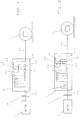
- Fig. 1
- schematically a power transmission path of a motor vehicle with powershift transmission;
- Fig. 2
- begin this power transmission path with a freewheel on the drive shaft against the gearbox.
Ein Motor 1 treibt über eine als nasse Lamellenkupplung
ausgebildete Anfahrkupplung 2 und ein Lastschaltgetriebe
3 sowie ein nachgeordnetes Ausgleichgetriebe 4 ein
Fahrzeug an.A motor 1 drives as a wet multi-plate clutch
trained starting
In der in Fig. 2 dargestellten Ausgestaltung der Erfindung verhindert ein mechanischer Freilauf 3.1 zwischen Getriebeantriebswelle 3.2 und Getriebegehäuse 3.3 ein Verdrehen dieser Welle entgegen der Motordrehrichtung. Dies bedingt bei im Lastschaltgetriebe 3 geschalteten Vorwärtsgängen eine Rückrollsperre und bei geschaltetem Rückwärtsgang eine Wegrollsperre nach vorne, d. h. in beiden Fällen eine Sperre gegen unbeabsichtigtes Wegrollen des Kraftfahrzeuges entgegen der durch die Gangwahl beabsichtigten Fahrtrichtung.In the embodiment of the invention shown in FIG. 2 prevents a mechanical freewheel 3.1 between Gearbox drive shaft 3.2 and gearbox housing 3.3 are twisted this shaft against the direction of motor rotation. This due to 3 forward gears engaged in the powershift transmission a rollback lock and when reverse gear is engaged a roll-away lock to the front, d. H. in both cases a lock against unintentional rolling away of the motor vehicle contrary to the one intended by the gear selection Direction of travel.
In der in Fig. 1 dargestellten Ausgestaltung der Erfindung
ist die Sperre, die ein Wegrollen des Fahrzeuges
entgegen der durch die Gangwahl beabsichtigten Fahrtrichtung
verhindert, als elektronisch geregelte Sperre ausgebildet,
die durch Aktivierung der vorstehend genannten
Schaltelemente-Kombination wirkt. Das Wegrollen des Kraftfahrzeuges
entgegen der durch die Gangwahl beabsichtigten
Fahrtrichtung wird in diesem Fall dadurch verhindert, daß
eine entsprechende Schaltelemente-Kombination im Getriebe
den Getriebeabtrieb blockiert. Dies geschieht folgendermaßen:
Die Bremsen D und E sind festgebremst und die Kupplung B ist geschaltet. Beginnt die
Die Bremsen D und E sind festgebremst und die Kupplung B ist geschaltet.
Die Bremsen D und E sind festgebremst und die Kupplung C ist geschaltet.
Brakes D and E are braked and clutch B is engaged. When the starting
Brakes D and E are braked and clutch B is engaged. When the starting
Brakes D and E are braked and clutch C is engaged. When the starting
Bei der selbständigen Lösung der der Erfindung zugrundeliegenden
Aufgabe in Form der geregelten Schaltkupplung
als Anfahreinrichtung, für die gesondert Schutz begehrt
wird, fällt die Anfahrkupplung 2 aus Fig. 1 weg. Die Kupplung
B ist dafür stärker dimensioniert und dient als Anfahrkupplung.
Zum Anfahren wird sie geregelt geschlossen,
der erste Gang wird damit geschaltet. Zum Rückwärts-Anfahren
wird die Kupplung C geregelt geschlossen. Diese
Kupplung ist als Anfahrkupplung ebenfalls stärker dimensioniert.
Das Anfahren im Rückwärtsgang ist allerdings nicht
so häufig wie das Vorwärts-Anfahren, so daß die Anforderung
in Hinblick auf Verschleiß an die Kupplung C nicht so hoch
sind wie die an die Kupplung B.In the independent solution of the basis of the invention
Task in the form of the regulated clutch
as a start-up device for which separate protection is required
the starting
Vorteilhaft werden durch Überschneidungsschaltungen die Kupplungen B und C weiter entlastet.Be advantageous by overlapping circuits the clutches B and C further relieved.
Das Vorwärts-Anfahren gestaltet sich dann folgendermaßen:
Die Bremsen D und E sind festgebremst und die Kupplung B
wird geschaltet. Beginnt die Kupplung B zu greifen, wird
die Bremse D in dem Maße losgelassen, in dem die Kupplung B
Moment aufnimmt.The forward approach is then as follows:
Brakes D and E are braked and clutch B is engaged. When clutch B begins to grip, brake D is released to the extent that clutch B takes up torque.
Das Rückwärts-Anfahren gestaltet sich analog folgendermaßen:
Die Bremsen D und E sind festgebremst und die Kupplung C
wird geschaltet. Beginnt die Kupplung C zu greifen, wird
die Bremse D in dem Maße losgelassen, in dem die Kupplung C
Moment aufnimmt.The reverse approach is analogous as follows:
Brakes D and E are braked and clutch C is engaged. When clutch C begins to grip, brake D is released to the extent that clutch C takes up torque.
Bei der zweiten selbständigen Lösung der der Erfindung
zugrundeliegenden Aufgabe, für die gesondert Schutz begehrt
wird, bei der eine geregelten Getriebebremse als Anfahreinrichtung
dient und eine Überschneidungsschaltung das
Wegrollen des Kraftfahrzeuges entgegen der durch die Gangwahl
beabsichtigten Fahrtrichtung durch Aktivierung der
Betriebsbremse verhindert, fällt die Anfahrkupplung 2 aus
Fig. 1 weg. Die Bremse E ist dafür stärker dimensioniert
und dient als Anfahrkupplung. Zum Anfahren im ersten Gang
ist die Kupplung B geschlossen. Die Betriebsbremsen sind
festgebremst, so daß das Fahrzeug nicht wegrollen kann.
Solange die Bremse E offen ist, kann sich der Planetenträger
3.10 frei drehen und überträgt damit kein Moment auf
das Hohlrad 3.8. Dabei rollt sich das mit dem Hohlrad 3.8
im Eingriff stehende Planetenrad 3.6 auf diesem ab. Zum
Anfahren wird nun die Bremse E geregelt geschlossen, und in
dem Maße, in dem der Planetenträger Moment aufnimmt, wird
die Betriebsbremse gelöst.
Zum Anfahren im Rückwärtsgang ist die Kupplung C geschlossen.
Das Anfahren erfolgt in gleicher Weise wie oben: Die
Betriebsbremsen sind festgebremst, so daß das Fahrzeug
nicht wegrollen kann. Solange die Bremse E offen ist, kann
sich der Planetenträger 3.10 frei drehen und überträgt damit
kein Moment auf das Hohlrad 3.8. Dabei rollt sich das
mit dem Hohlrad 3.8 im Eingriff stehende Planetenrad 3.6
auf diesem ab. Zum Anfahren wird nun die Bremse E geregelt
geschlossen, und in dem Maße, in dem der Planetenträger
Moment aufnimmt, wird die Betriebsbremse gelöst. In the second independent solution to the problem on which the invention is based, for which protection is sought separately, in which a regulated transmission brake serves as a starting device and an overlap circuit prevents the motor vehicle from rolling away against the direction of travel intended by the gear selection by activating the service brake, the starting
Clutch C is closed for starting in reverse gear. The vehicle starts off in the same way as above: The service brakes are braked so that the vehicle cannot roll away. As long as the brake E is open, the planet carrier 3.10 can rotate freely and therefore does not transmit any torque to the ring gear 3.8. The planet gear 3.6, which is in engagement with the ring gear 3.8, rolls on the latter. To start off, the brake E is now closed in a controlled manner, and the service brake is released to the extent that the planet carrier takes up torque.
- 11
- Motorengine
- 22nd
- AnfahrkupplungStarting clutch
- 33rd
- LastschaltgetriebePowershift transmission
- 3.13.1
- FreilaufFreewheel
- 3.23.2
- GetriebeantriebswelleGearbox input shaft
- 3.33.3
- GetriebegehäuseGear housing
- 3.43.4
- SonnenradSun gear
- 3.53.5
- PlanetenradPlanet gear
- 3.63.6
- PlanetenradPlanet gear
- 3.73.7
- SonnenradSun gear
- 3.83.8
- HohlradRing gear
- 3.93.9
- GetriebeabtriebswelleTransmission output shaft
- 3.103.10
- PlanetenträgerPlanet carrier
- 44th
- AusgleichgetriebeDifferential gear
Claims (13)
- A power shift transmission for motor vehicles with an upstream starter device, which is constructed as an upstream starter clutch (2), as a shift clutch, as a controlled disk clutch or as a gearing brake, characterised in that a lock is provided, which prevents the motor vehicle from rolling away in the opposite direction to the direction of travel intended by the gear selection, the lock being constructed as an idler (3.1) or as an electronically controlled lock or as a gearing brake.
- A power shift transmission according to claim 1, characterised in that the idler (3.1) acting as a lock acts upon a shaft, which always rotate in the same direction during forward and reverse travel when driven by the drive machine, and prevents the shaft from rotating in the opposite direction when the drive is interrupted.
- A power shift transmission according to claim 1 or 2, characterised in that the idler (3.1) is constructed as a clamping element idler or a pawl idler.
- A power shift transmission according to one of the preceding claims, characterised in that the idler (3.1) is fitted on the drive shaft of the power shift transmission (3), more particularly in the region of the disk clutch.
- A power shift transmission (3) according to claim 1, characterised in that the electronically controlled lock acts by actuating the operating brake.
- A power shift transmission according to one of the preceding claims, characterised in that the gearing brake acts upon one or more components of a planetary gearing.
- A power shift transmission according to one of the preceding claims, characterised in that the gearing brake and the starter clutch (2) of the power shift transmission (3) are controlled by an overlap control.
- A power shift transmission according to claim 7, characterised in that the overlap control is controlled as a function of the slope output power.
- A power shift transmission according to claim 8, characterised in that the slope output power is calculated by way of its effect on the gearing output shaft (3.9).
- A power shift transmission according to claim 8, characterised in that the slope output power is determined by means of a force or torque sensor.
- A power shift transmission according to claim 8, characterised in that the slope output power is determined by means of an inclination sensor.
- A power shift transmission according to claim 8, characterised in that the slope output power is determined via the gradient of the gearing output rotational speed.
- A power shift transmission according to one of the preceding claims, characterised in that the disk clutch is constructed as a wet clutch.
Applications Claiming Priority (3)
| Application Number | Priority Date | Filing Date | Title |
|---|---|---|---|
| DE19625355 | 1996-06-25 | ||
| DE19625355A DE19625355A1 (en) | 1996-06-25 | 1996-06-25 | Power shift transmission for motor vehicles |
| PCT/EP1997/003198 WO1997049573A1 (en) | 1996-06-25 | 1997-06-19 | Power shift transmission for motor vehicles |
Publications (2)
| Publication Number | Publication Date |
|---|---|
| EP0907525A1 EP0907525A1 (en) | 1999-04-14 |
| EP0907525B1 true EP0907525B1 (en) | 2000-03-22 |
Family
ID=7797936
Family Applications (1)
| Application Number | Title | Priority Date | Filing Date |
|---|---|---|---|
| EP97929220A Expired - Lifetime EP0907525B1 (en) | 1996-06-25 | 1997-06-19 | Power shift transmission for motor vehicles |
Country Status (5)
| Country | Link |
|---|---|
| US (1) | US6244402B1 (en) |
| EP (1) | EP0907525B1 (en) |
| JP (1) | JP2000512591A (en) |
| DE (2) | DE19625355A1 (en) |
| WO (1) | WO1997049573A1 (en) |
Families Citing this family (13)
| Publication number | Priority date | Publication date | Assignee | Title |
|---|---|---|---|---|
| DE19921200A1 (en) * | 1999-05-07 | 2000-11-09 | Bayerische Motoren Werke Ag | Roll-away protection for motor vehicles |
| DE19932613A1 (en) | 1999-07-13 | 2001-01-18 | Zahnradfabrik Friedrichshafen | Automatic transmission |
| DE19949856A1 (en) * | 1999-10-15 | 2001-04-19 | Zahnradfabrik Friedrichshafen | Multi-stage shifting gearbox, especially for commercial vehicles has pre-shift group designed as planetary drive and support member is designed as friction brake effective in slow shift position |
| SE0004715D0 (en) | 2000-12-20 | 2000-12-20 | Haldex Brake Prod Ab | A transmission brake |
| US7066304B2 (en) | 1999-12-02 | 2006-06-27 | Haldex Brake Products Ab | Disc brake |
| DE10135744A1 (en) * | 2001-07-21 | 2003-02-06 | Zahnradfabrik Friedrichshafen | Arrangement for preventing vehicle from rolling backwards, has brake that acts on vehicle gearbox operated while vehicle is stationary or almost stationary in addition to vehicle brakes |
| US6827664B2 (en) * | 2001-11-15 | 2004-12-07 | General Motors Corporation | Transmission |
| DE10161815A1 (en) | 2001-12-14 | 2003-06-26 | Borgwarner Inc | Device for starting a motor vehicle equipped with an automatic transmission arrangement |
| US7357754B2 (en) * | 2005-07-22 | 2008-04-15 | Gm Global Technology Operations, Inc. | Mechanism and method of controlling an automatic shifting power transmission to effect a first gear launch |
| DE102007044683B4 (en) | 2007-09-19 | 2018-06-07 | Dr. Ing. H.C. F. Porsche Aktiengesellschaft | Double clutch transmission with freewheel |
| JP4922224B2 (en) * | 2008-03-27 | 2012-04-25 | 正博 大窪 | Multi-speed automatic transmission |
| AU2010295219B2 (en) * | 2009-09-21 | 2016-07-07 | Nt Consulting International Pty Limited | Transmission with hill hold feature |
| DE102017111768A1 (en) * | 2017-05-30 | 2018-12-06 | Schaeffler Technologies AG & Co. KG | Transmission output arrangement |
Family Cites Families (13)
| Publication number | Priority date | Publication date | Assignee | Title |
|---|---|---|---|---|
| DE2003977A1 (en) * | 1970-01-29 | 1971-08-19 | Werner Schlosser | Rollback lock for vehicles of all kinds |
| US4487303A (en) * | 1982-12-27 | 1984-12-11 | Ford Motor Company | Automatic transmission start-up clutch control system |
| ZA853198B (en) | 1984-05-26 | 1985-12-24 | Zahnradfabrik Friedrichshafen | Epicyclic gear unit |
| JPS6199747A (en) * | 1984-10-19 | 1986-05-17 | Nissan Motor Co Ltd | Creep torque control device of automatic speed change gear |
| DE3621076A1 (en) * | 1986-06-24 | 1988-01-14 | Opel Adam Ag | BRAKE DEVICE FOR VEHICLES WITH START-UP DEVICE |
| DE3813516A1 (en) * | 1988-04-22 | 1989-11-02 | Bayerische Motoren Werke Ag | GEARBOX UNIT FOR MOTOR VEHICLES |
| US4867291A (en) * | 1988-06-28 | 1989-09-19 | Dana Corporation | Vehicle transmission hill holder with releasable one way clutch |
| US4968368A (en) | 1989-08-11 | 1990-11-06 | Steelastic West, Inc. | Method and apparatus for lining vessels |
| EP0712754B1 (en) * | 1991-06-03 | 1999-11-10 | New Holland U.K. Limited | Driveline engagement/disengagement |
| JP2878964B2 (en) | 1994-05-02 | 1999-04-05 | アイシン・エィ・ダブリュ株式会社 | Control method and control device for automatic transmission |
| US5474164A (en) * | 1994-05-09 | 1995-12-12 | Ford Motor Company | Vehicle transmission hill holder |
| DE4442991A1 (en) * | 1994-12-02 | 1996-06-05 | Zahnradfabrik Friedrichshafen | Automatic drive |
| DE19546707A1 (en) * | 1995-12-14 | 1997-06-19 | Bayerische Motoren Werke Ag | Drive device for a motor vehicle |
-
1996
- 1996-06-25 DE DE19625355A patent/DE19625355A1/en not_active Withdrawn
-
1997
- 1997-06-19 EP EP97929220A patent/EP0907525B1/en not_active Expired - Lifetime
- 1997-06-19 WO PCT/EP1997/003198 patent/WO1997049573A1/en not_active Ceased
- 1997-06-19 DE DE59701324T patent/DE59701324D1/en not_active Expired - Lifetime
- 1997-06-19 US US09/202,262 patent/US6244402B1/en not_active Expired - Lifetime
- 1997-06-19 JP JP10502286A patent/JP2000512591A/en active Pending
Also Published As
| Publication number | Publication date |
|---|---|
| US6244402B1 (en) | 2001-06-12 |
| EP0907525A1 (en) | 1999-04-14 |
| JP2000512591A (en) | 2000-09-26 |
| DE59701324D1 (en) | 2000-04-27 |
| WO1997049573A1 (en) | 1997-12-31 |
| DE19625355A1 (en) | 1998-01-02 |
Similar Documents
| Publication | Publication Date | Title |
|---|---|---|
| DE3935570C2 (en) | Gear change transmission for motor vehicles | |
| EP0907525B1 (en) | Power shift transmission for motor vehicles | |
| DE102019114139B3 (en) | Automotive transmission | |
| DE10033476B9 (en) | Drive train of an automatic transmission | |
| DE10307789A1 (en) | Automatic gearbox, comprising six forward gears and specifically arranged brake and clutch system | |
| DE69503691T2 (en) | Multi-speed gearbox with parallel axes | |
| DE19530486A1 (en) | Automatic transmission powertrain for a vehicle | |
| DE3906251A1 (en) | HYDRAULIC CONTROL DEVICE FOR AN AUTOMATIC TRANSMISSION | |
| DE19536952C2 (en) | Hydrodynamic torque converter with lock-up clutch | |
| DE2937366A1 (en) | TRANSMISSION | |
| DE3919174C2 (en) | ||
| DE3812623A1 (en) | AUTOMATIC TRANSMISSION | |
| DE2038600C2 (en) | Gear change transmissions for vehicles | |
| DE4313167C2 (en) | Gearbox switchable under load | |
| EP1080321A1 (en) | Hydrodynamic, mechanical multi-speed compound transmission | |
| WO2008019778A1 (en) | Automatic shift transmission | |
| DE19961820A1 (en) | Drive train for automatic gear mechanism; has combination planetary gear set with two gear sets connected and having individual pinions and has three input units, two output units and two brake units | |
| DE102004060642B4 (en) | Control device for a power shift transmission | |
| DE4328889C1 (en) | Planetary gear transmission for the drive of a vehicle | |
| DE3740781C1 (en) | Arrangement for automatic switching of a planetary gear change transmission of a motor vehicle | |
| EP1342660B1 (en) | Clutch control, in particular for bicycle hub transmissions | |
| DE3407160C2 (en) | Planetary gear change transmission with a forward gear designed as an overdrive | |
| DE102007044683B4 (en) | Double clutch transmission with freewheel | |
| EP1565677A1 (en) | Power transmission unit | |
| DE720797C (en) | Four-speed planetary gear for motor vehicles |
Legal Events
| Date | Code | Title | Description |
|---|---|---|---|
| PUAI | Public reference made under article 153(3) epc to a published international application that has entered the european phase |
Free format text: ORIGINAL CODE: 0009012 |
|
| 17P | Request for examination filed |
Effective date: 19980917 |
|
| AK | Designated contracting states |
Kind code of ref document: A1 Designated state(s): DE FR GB IT |
|
| GRAG | Despatch of communication of intention to grant |
Free format text: ORIGINAL CODE: EPIDOS AGRA |
|
| 17Q | First examination report despatched |
Effective date: 19990511 |
|
| GRAG | Despatch of communication of intention to grant |
Free format text: ORIGINAL CODE: EPIDOS AGRA |
|
| GRAH | Despatch of communication of intention to grant a patent |
Free format text: ORIGINAL CODE: EPIDOS IGRA |
|
| ITF | It: translation for a ep patent filed | ||
| GRAH | Despatch of communication of intention to grant a patent |
Free format text: ORIGINAL CODE: EPIDOS IGRA |
|
| GRAA | (expected) grant |
Free format text: ORIGINAL CODE: 0009210 |
|
| AK | Designated contracting states |
Kind code of ref document: B1 Designated state(s): DE FR GB IT |
|
| GBT | Gb: translation of ep patent filed (gb section 77(6)(a)/1977) |
Effective date: 20000322 |
|
| REF | Corresponds to: |
Ref document number: 59701324 Country of ref document: DE Date of ref document: 20000427 |
|
| ET | Fr: translation filed | ||
| PLBE | No opposition filed within time limit |
Free format text: ORIGINAL CODE: 0009261 |
|
| STAA | Information on the status of an ep patent application or granted ep patent |
Free format text: STATUS: NO OPPOSITION FILED WITHIN TIME LIMIT |
|
| 26N | No opposition filed | ||
| REG | Reference to a national code |
Ref country code: GB Ref legal event code: IF02 |
|
| PGFP | Annual fee paid to national office [announced via postgrant information from national office to epo] |
Ref country code: IT Payment date: 20060630 Year of fee payment: 10 |
|
| PG25 | Lapsed in a contracting state [announced via postgrant information from national office to epo] |
Ref country code: IT Free format text: LAPSE BECAUSE OF NON-PAYMENT OF DUE FEES Effective date: 20070619 |
|
| PGFP | Annual fee paid to national office [announced via postgrant information from national office to epo] |
Ref country code: FR Payment date: 20100709 Year of fee payment: 14 |
|
| PGFP | Annual fee paid to national office [announced via postgrant information from national office to epo] |
Ref country code: GB Payment date: 20100616 Year of fee payment: 14 |
|
| GBPC | Gb: european patent ceased through non-payment of renewal fee |
Effective date: 20110619 |
|
| REG | Reference to a national code |
Ref country code: FR Ref legal event code: ST Effective date: 20120229 |
|
| PG25 | Lapsed in a contracting state [announced via postgrant information from national office to epo] |
Ref country code: FR Free format text: LAPSE BECAUSE OF NON-PAYMENT OF DUE FEES Effective date: 20110630 |
|
| PG25 | Lapsed in a contracting state [announced via postgrant information from national office to epo] |
Ref country code: GB Free format text: LAPSE BECAUSE OF NON-PAYMENT OF DUE FEES Effective date: 20110619 |
|
| PGFP | Annual fee paid to national office [announced via postgrant information from national office to epo] |
Ref country code: DE Payment date: 20130612 Year of fee payment: 17 |
|
| REG | Reference to a national code |
Ref country code: DE Ref legal event code: R119 Ref document number: 59701324 Country of ref document: DE |
|
| PG25 | Lapsed in a contracting state [announced via postgrant information from national office to epo] |
Ref country code: DE Free format text: LAPSE BECAUSE OF NON-PAYMENT OF DUE FEES Effective date: 20150101 |
|
| REG | Reference to a national code |
Ref country code: DE Ref legal event code: R079 Ref document number: 59701324 Country of ref document: DE Free format text: PREVIOUS MAIN CLASS: B60K0041220000 Ipc: B60W0010020000 |