EP0907291A2 - Méthode, système et dispositifs de détection de vecteurs de mouvement - Google Patents
Méthode, système et dispositifs de détection de vecteurs de mouvement Download PDFInfo
- Publication number
- EP0907291A2 EP0907291A2 EP19980118570 EP98118570A EP0907291A2 EP 0907291 A2 EP0907291 A2 EP 0907291A2 EP 19980118570 EP19980118570 EP 19980118570 EP 98118570 A EP98118570 A EP 98118570A EP 0907291 A2 EP0907291 A2 EP 0907291A2
- Authority
- EP
- European Patent Office
- Prior art keywords
- row
- column
- frames
- image
- motion vector
- Prior art date
- Legal status (The legal status is an assumption and is not a legal conclusion. Google has not performed a legal analysis and makes no representation as to the accuracy of the status listed.)
- Ceased
Links
Images


Classifications
-
- H—ELECTRICITY
- H04—ELECTRIC COMMUNICATION TECHNIQUE
- H04N—PICTORIAL COMMUNICATION, e.g. TELEVISION
- H04N19/00—Methods or arrangements for coding, decoding, compressing or decompressing digital video signals
- H04N19/40—Methods or arrangements for coding, decoding, compressing or decompressing digital video signals using video transcoding, i.e. partial or full decoding of a coded input stream followed by re-encoding of the decoded output stream
-
- H—ELECTRICITY
- H04—ELECTRIC COMMUNICATION TECHNIQUE
- H04N—PICTORIAL COMMUNICATION, e.g. TELEVISION
- H04N19/00—Methods or arrangements for coding, decoding, compressing or decompressing digital video signals
- H04N19/50—Methods or arrangements for coding, decoding, compressing or decompressing digital video signals using predictive coding
- H04N19/503—Methods or arrangements for coding, decoding, compressing or decompressing digital video signals using predictive coding involving temporal prediction
- H04N19/51—Motion estimation or motion compensation
Definitions
- the invention generally relates to a motion vector detector for use in a motion-compensated video coder and, more particularly, to a motion vector detecting method and system suited for software implementation for providing relatively high-precision motion vectors at a passable speed.
- a reduction in special redundancy in coded video frames is achieved by motion-compensated coding.
- motion-compensated coding an object block 102 of a current frame 101 being coded is coded by searching a search range 103 defined around the corresponding block 104 in a past frame 105 for a block having the maximum correlation with the object block, i.e., a maximum correlation block 106; calculating a motion vector 107 from the corresponding block 104 to the detected maximum correlation block 106 and a block of difference data between the object block 102 and the maximum correlation block 106 as shown in FIG. 1; and coding the vector and the block of difference data.
- the detection of motion vector is performed for each macroblock, i.e., by a unit of 2x2 blocks.
- FIG. 2 illustrates three of such algorithms.
- algorithm (a) the number of matching operations is reduced by half by executing a matching operation every two bits in a search range 103a instead of conducting a full search.
- steps (precision) of the motion vectors are also halved.
- algorithm (a) searching a full search range 103b with sampled data from the object block 102b reduces the amount of data in a matching operation. Though the steps of the motion vectors are the same as in case of ordinary full search, the reliability of the steps lowers.
- algorithm (c) searches are made not in a constant interval like every two bits but in a variable interval.
- a range 103c is first searched in a larger interval for a representative matching point and then only the neighborhood of the matching point is searched in a decreasing interval for a motion vector.
- the amount of code data per frame compressed by the DV scheme reaches six times that of code data compressed by a standard MPEG 2 scheme. From this viewpoint, MPEG coded data is more suitable for transmission of a video signal through a network such as PSTN (public switched telephone network).
- PSTN public switched telephone network
- the frames of DV data is advantageously independent from one another, which facilitates video editing through frame-based cut and paste.
- DV data yields pictures of much the better quality for its plenty of codes.
- a method of detecting a motion vector for an object block in a current frame of an orthogonally transformed video with respect to a stored reference frame comprises the steps of: extracting a predetermined pattern of lower frequency components from the object block; orthogonally inverse transform the extracted lower frequency components within the pattern to yield the pattern of pixel data; searching the reference frame for a block having a maximum correlation with the pattern of pixel data; and calculating the motion vector from the object block to the block having a maximum correlation.
- DCT discrete cosine transform
- top row and the leftmost column as the predetermined pattern provides the same level of precision as in case of a two-dimension full search. This is achieved by the steps of: extracting a top row of components from the object block; orthogonally inverse transform the extracted components within the row to yield row pixels; advancing along and searching top rows of the reference frame for a row image having a maximum correlation with the row pixels; calculating an x-component of the motion vector from the top row of the object block to the row image. The same process is also applied to the leftmost column.
- a motion vector detector may be applied to video coders of MPEG, H.261 and H.263, and to a DV-to-MPEG converter.
- the motion vector detector provides a motion vector of a low precision at a very high speed. This embodiment is preferably used in combination with a higher precision motion vector detector.
- creating a row and a column image comprising sums obtained by adding all the pixels in each column and each row of the object block and applying the above searching and calculating process to the row and the column image enables the motion vector detection from a normal or noncompressed video.
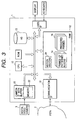
- FIG. 3 is a schematic block diagram showing an exemplary hardware system 1 on which the invention is embodied.
- the hardware system 1 may be any suitable computer provided with the following features.
- the computer 1 preferably comprises a high speed CPU (central processing unit) 10; a memory (RAM) 12 with a sufficient capacity for storing several frames 14 of patterned blocks (detailed later) used in motion vector detection, several frames 16 of predicted pictures used in motion compensation of MPEG coding if the invention is applied to an MPEG coder and various intermediate data; and a communication interface (IF) 18 for communicating video data through a pubic switched telephone network (PSTN) 2.
- a high speed CPU central processing unit
- RAM memory
- IF communication interface
- the computer 1 preferably has a camera interface (IF) 20 with a buffer function which includes at least a frame's worth of memory 22 so that the computer 1 can take in moving pictures from a digital video camera 3.
- IF camera interface
- FIG. 4 is a flowchart showing an exemplary operation executed by CPU 10 under the control of a motion vector detector program 4 for detecting a motion vector of an object block of a current frame with respect to a reference frame of past frames 14 in accordance with the principles of the invention. It is assumed that the current frame is one, of the frames or pictures in an orthogonally transformed video supplied through the camera interface 20 or the communication IF 18, which is being processed now.
- the reference frame is one of the past frames 14 stored in RAM 12 which is being used as a reference of the motion vector detection for the current frame.
- the motion vector detecting program is applied to an PMEG coder, then which of the past frames 14 to use as the reference frame is determined by a main routine of the MPEG coder program stored in a hard disk (HD) 13 in case of software implementation or by a controller of the PMEG coder (not shown) in case of hardware implementation.
- a main routine of the MPEG coder program stored in a hard disk (HD) 13 in case of software implementation or by a controller of the PMEG coder (not shown) in case of hardware implementation.
- DCT discrete cosine transform
- CPU 10 first read the object block specified by the main routine from the current frame comprised blocks of orthogonally transformed image data in step 40.
- step 42 CPU 10 extracts a predetermined pattern of lower frequency components (i.e., coefficients for lower frequency terms) from the object block.
- lower frequency components i.e., coefficients for lower frequency terms
- larger values tend to concentrate to lower frequency coefficients in an orthogonally transformed block as is well known in the art.
- lower frequency coefficients contain major part of the information of the entire block. Therefore, extracting lower frequency components from each block enables a decrease in information quantity caused by the sampling of coefficients to be held down to a satisfactorily low level.
- CPU 10 orthogonally inverse transforms the extracted lower frequency components within the pattern.
- CPU 10 searches a search range in the reference frame for a block having the maximum correlation with the object block. Specifically, a sum of absolute difference (SAD) between the object block and a tested block is calculated while advancing the tested block by one pixel within the search range after each test. Then, a block having the minimum SAD is detected.
- SAD sum of absolute difference
- step 48 CPU 10 calculates the motion vector from the object block to the found block. Finally, the CPU stores the motion vector in an assigned location in a motion vector storage area 24 in RAM 12 and ends the operation.
- FIG. 5 is a flowchart showing an exemplary operation of a DV-to-MPEG format converter program 5 incorporating a motion vector detector program 506 in accordance with a first illustrative embodiment of the invention.
- frames are either intra coded or predictive coded. Since intra coding has no need for motion compensation and accordingly no need for motion vectors. For this reason, it is assumed that the program 5 is executed only for predictive coded frames.
- the object block is a block being processed at present.
- step 54 CPU 10 makes a test to see if the object block is the first block or top leftmost block of the macroblock to which the object block belongs, i.e., if both Bx and By are odd numbers. If so, CPU 10 detects a motion vector (MV) for the object block to store the detected MV in the MV storage area 24 as detailed below. Otherwise, CPU 10 proceeds to step 58 omitting the MV detection. This is because a motion vector is to be detected for each macroblock in MPEG coding.
- MV motion vector
- step 56 CPU 10 decodes the DV format object block into an uncompressed data block in step 58 (DV decoder).
- step 60 CPU 10 MPEG encodes the uncompressed data block into an MPEG coded block by using a MV data in the MV storage area 24.
- step 62 CPU 10 makes a test to see if the object block coordinates have reached the end block of the current frame. If so, CPU exits from the DV-to-MPEG format converter program 5. Otherwise, CPU advances the object block coordinates to the next block in step 64, and returns to step 54. In this way, the DV format is successfully converted to the MPEG format.
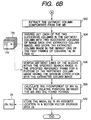
- Figs. 6A and 6B when combined at encircled “A", constitute a flowchart showing an operation of a motion vector (MV) detector program 506 according to the principles of the invention. It is assumed that the main program 5 informs the MV detector program 506 of which of the past frames in the past frame storage area 14 should be used as a reference frame with respect to which a MV of the object block is detected and a search range within which the MV detection for the object block is conducted.
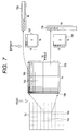
- FIG. 7 shows the way a predetermined pattern of lower frequency components is extracted from the current macroblock.
- step 520 CPU 10 first reads the object macroblock 703 from the current frame 701 comprised of DCT blocks. Since this program 506 is executed at the beginning of a macroblock (MB) (e.g., 702), the object MB 703 comprises four DCT blocks including the object DCT block 702 in the upper left position as shown in FIG. 7. In step 522, CPU 10 extracts a predetermined pattern of lower frequency components or DCT coefficients from the object MB 703.
- MB macroblock
- the predetermined pattern comprises the top row of a MB and the leftmost column of the MB. Accordingly, a mask 707 comprising a top row of the 16 elements being all 1's and the following 15 rows of all 0's in 16 elements is used to extract the top row 705 from the object MB 703 in step 522.
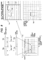
- step 524 CPU 10 inverse DCTs each of the two successive rows 705a and 705b in the top row 705 into two successive rows 715a and 715b of image data (hereinafter, referred to as the extracted row image 715); and stores the extracted rows image 715 in the newest one (14x-1) of the past frames of rows (one dimension image), 14x, in RAM 12 as shown in FIG. 8. In this way, extracted row images obtained so far have been stored in respective frames in the past frame storage area in RAM 12. It is noted that the past frame storage area of RAM 12 is wide enough to accommodate several past frames of one dimension image for both rows and columns (described below).
- step 526 CPU 10 searches top lines of the blocks within the specified search range 717 in the specified reference frame (14x-i) for a portion of the reference row image 14x-i having the maximum correlation with the extracted rows image 715 as shown in FIG. 8.
- the extracted row image (or x-direction one-dimensional (or row) image) 715 is advanced one pixel by one along each of the lines in a search range 717 of the reference frame (14x-i) specified by the main routine (the DV-to-MPEG converter program 5 in this case).
- SAM sum of absolute difference
- step 528 CPU 10 calculates the x-component of the MV, Vx, from the relative position between the object MB and the detected portion. If the portion with the minimum SAM is at the position 718, then the x-component of the MV is detected as the length 719.
- the y-component of the MV can be detected as shown in FIG. 6B.
- step 532 CPU 10 extracts the leftmost column components 706 from the object MB 703.
- step 534 CPU 10 inverse DCTs each of the two successive columns in the leftmost column into two successive columns of image data (or the extracted row image), and stores the extracted row image in the newest one of the past frames of columns, 14y, in RAM 12.
- step 536 CPU 10 searches leftmost lines of the blocks within the specified search range in the specified reference frame for a portion of the reference column image having the maximum correlation with the extracted column image.
- step 538 CPU 10 calculates the y-component of the MV, Vy, from the relative positions between the object MV and the found portion.
- step 540 CPU 10 stores the MV (Vx, Vy) in an assigned location (assigned to the object MB) in a motion vector storage area 24. This enables the main program 5 to use motion vectors for motion compensation.
- the preciseness of MVs can be raised by calculating intermediate row images from adjacent row images of the reference row image 14x-i and interpolating the intermediate row images in between adjacent row images. This is also true to the y-component of the MV.
- the MV detection is achieved by using both of x-direction components and y-direction components extracted from a two-dimension DCTed video. This provides the same precision as in case where a full search is performed on a two-dimension area.
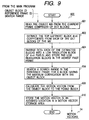
- FIG. 9 is a flowchart showing an exemplary operation of a MV detector program 600 in accordance with a second illustrative embodiment of the invention.
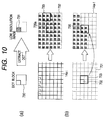
- FIG. 10 is a diagram showing how a MV is detected in accordance with the principles of the invention.
- CPU 10 first reads the object MV 703 from the current frame 701 comprised of DCT blocks 730 in step 601. In step 602, CPU 10 extracts the top leftmost block of 4x4 coefficients from each of the DCT blocks of the MB.
- step 604 CPU 10 inverse DCTs each of the extracted blocks into a low resolution block 731 of 4x4 pixels; and stores the low resolution blocks 735 in the newest one (14a-1) of the past frames 14a stored in a past frame storage area 14 in RAM 12.
- step 606 CPU 10 searches a search range732 in the reference frame (14a-i) for a block 733 having the maximum correlation with the low-resolution blocks 735 as shown in FIG. 10. The matching is achieved by calculating the SAD between the four low-resolution blocks 735 and each combination of 2x2 blocks in the search range 732. Once the four blocks 733 with the minimum SAD is found, CPU 10 calculates the motion vector from the object block to the found blocks 733 in step 608. Finally, CPU 10 stores the motion vector in an assigned location in a motion vector storage area 24.
- 2x2 coefficients may be extracted for a faster MV detection.
- this scheme fails to detect the length and the direction of the MV with a small step. For example, if a block of 4x4 pixels is used, motion vectors can be detected only with twice the step in case of a full search.
- this embodiment is preferably used for limiting the search range. Specifically, this scheme is first used for limiting the search area; a high precision MV detecting techniques such as a full search or the system as described in a first embodiment is applied to the limited search range to obtain a final MV. By doing this, a high precision MV detection is achieved as a whole in a short period.
- FIG. 11 is a flowchart showing an operation of a motion vector (MV) detector program 506a according to the principles of the invention.
- the MV detector program 506a of FIG. 11 is identical to that of Figs. 6A and 6B except that in FIG. 11 the steps 530 and 536 have been replaced with 530a and 536a, respectively.
- FIG. 12 shows a novel way of detecting the y-component of the MV.
- the numeral 703 is the object MB of the current frame 701
- the numerals 715 and 716 are the extracted row and column images from the MB 703 as described above.
- CPU 10 after calculating the x component of the MV, Vx, from the relative position between the extracted row image 715 (or MB 703) and the found portion 718 in the search range 717 in the reference row image in step 538, CPU 10 saves the x component Vx and the number N L of the lines that lies above and includes the found portion 718 for subsequent use in step 530a.
- CPU 10 searches leftmost lines of the blocks within a square range 732 defined around (X+Vx, N L ) in the specified reference frame for a portion of the reference column image having the maximum correlation with the extracted column image.
- the variable X is a distance in pixels from the leftmost side of the frame to the object MB 703.
- the square range 732 where a search for y component is conducted can be set much smaller than the search range 730. This reduces searching operation resulting in a raised speed of MV detection.
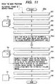
- FIG. 13 shows an operation of a motion vector (MV) detector program 6 for detecting a motion vector from an ordinary video data in accordance with the principles of the invention.
- the program 6 of FIG. 13 is identical to that of Figs. 6A and 6B except that the steps 520, 522, 524, 532 and 534 have been replaced with steps 620, 622, 624, 632 and 634, respectively in FIG. 13. So, only the differences are described in the following.
- MV detector 6 of this embodiment is an extension of the principles applied to the first embodiment.
- an MV detector 6 deals with ordinary (noncompressed) moving pictures, it is assumed that the MV detector 6 is applied to an MPEG coder.
- CPU first read the object MB specified by a main program (the MPEG decoder in this example) from the current frame of an input (noncompressed) video in step 620.
- CPU creates a row image 742 comprised of 16 sums obtained by adding all the pixels in each of the columns of the MB 740 as shown in FIG. 14.
- CPU stores the row image 742 in the newest one (14x-1) of the past frames 14x of rows in RAM 12.
- a column image 744 comprised of 16 sums is created by adding all the pixels in each of the rows of the MB 740 as shown in FIG. 14.
- the column image 744 is stored in the newest one (14y-1) of the past frames 14y of columns in RAM 12.
- the equation (1) indicates a one-dimension DCT.
- f is a value of pixel
- F is converted DCT coefficients
- N is a number indicative of a limit of the conversion domain
- u is a parameter indicative of the direction of the one dimension.
- C(w) is a constant with a value as shown in equation (2).
- Equation (3) indicates a two-dimension DCT to which the equation (1) has been extended.
- equation (4) a substitution with equation (5) is made.
- G(u) in the fourth line of equation (4) is what is obtained by applying a one-dimension DCT to g(j). Since constants in DCT have essentially no significance, if the constants are neglected, it is concluded that the DCT coefficients of the 0th column are equivalent to those into which g is one dimension DCTed with respect to the x direction.
- the extracted column image 716 is the 0th-column DCT coefficients expressed by equation (4), i.e., what results from a one-dimension.
- What results from a one-dimension inverse DCT of F(u,0) is just g(j). Since "j" indicates a row of the block, g(j) of equation (5) is a sum of the pixels of the row j.
- the y-direction one-dimension image 716 obtained in the one-dimension inverse DCT step 534 is equivalent to the row image 742 obtained in steps 632.
- the x direction it is also true to the x direction.
- representative one-dimension image is created for each direction (x, y) from a two dimension image; a motion vector is detected by using the representative one-dimension image.
- This enables motion vector detection of the same precision as in case of full search.
- a MV detector according to the third embodiment can detect a motion vector with a higher precision at a higher speed.
- the past frames which are used as a reference frame in the detection of motion vector has been generated from the input video.
- generating the past frames from the DCT blocks intermediately generated by the decoder incorporated in the MPEG encoder results in such moving vectors as to keep down pixel values in a block difference to a small level, causing the enhancement of the compression efficiency and the picture quality.
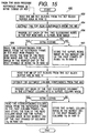
- FIG. 15 a flowchart showing an operation of a program 650, for use in a MV detector, for generating past frames from the DCT blocks supplied from the MPEG coder in which the MV detector is incorporated. It is assumed that information on the reference frame ID and whether the current frame being processed is intra coded (i.e., motion compensated) is given to the program 650.
- the decoder in the MPEG coder has to store the dequantized DCT blocks in, for example, a DCT block buffer area (not shown) in RAM 12. Also it is noted that the MPEG coder which incorporate the program 650 have no need of the storing operation of step 524, 534, 604, 624, 634.
- CPU 10 reads the MB of DCT blocks from the DCT block buffer area in RAM 12 in step 652.
- the top row components are extracted from the DCT MB.
- each of the two successive rows in the top row is inverse DCTed into 16-pixel rows image.
- a test is made to see if the current frame is intra coded (motion compensated). If so, then, in step 658, CPU 10 reads the corresponding row image from the reference frame in the past row frames 14x; and store the sum of the read row image and the 16-pixel row image in the newest one of the past frames of rows 14x in RAM 12. Otherwise, CPU 10 stores the 16-pixel rows image as it is in the newest one of the past frames of rows 14x in RAM 12 in step 660. Thereafter, the similar operation is executed with respect to the y-direction as shown in FIG. 15.
- the past frames are generated by using DCT blocks intermediately generated by the decoder portion of the MPEG coder.
- a motion vector may be detected by: obtaining blocks from the frame memory for use in the MPEG coder for storing predicted pictures; and creating the row and column images by summation from the obtained blocks.
Landscapes
- Engineering & Computer Science (AREA)
- Multimedia (AREA)
- Signal Processing (AREA)
- Compression Or Coding Systems Of Tv Signals (AREA)
- Television Signal Processing For Recording (AREA)
- Image Analysis (AREA)
Priority Applications (1)
| Application Number | Priority Date | Filing Date | Title |
|---|---|---|---|
| EP20040026452 EP1503598A1 (fr) | 1997-10-01 | 1998-10-01 | Methode, système et dispositifs de détection de vecteurs de mouvement |
Applications Claiming Priority (6)
| Application Number | Priority Date | Filing Date | Title |
|---|---|---|---|
| JP283162/97 | 1997-10-01 | ||
| JP28316297 | 1997-10-01 | ||
| JP28316297 | 1997-10-01 | ||
| JP229949/98 | 1998-08-03 | ||
| JP22994998 | 1998-08-03 | ||
| JP22994998A JP3667105B2 (ja) | 1997-10-01 | 1998-08-03 | 動きベクトル検出方法及びその方法を実施する装置 |
Related Child Applications (1)
| Application Number | Title | Priority Date | Filing Date |
|---|---|---|---|
| EP20040026452 Division EP1503598A1 (fr) | 1997-10-01 | 1998-10-01 | Methode, système et dispositifs de détection de vecteurs de mouvement |
Publications (2)
| Publication Number | Publication Date |
|---|---|
| EP0907291A2 true EP0907291A2 (fr) | 1999-04-07 |
| EP0907291A3 EP0907291A3 (fr) | 2002-03-27 |
Family
ID=26529076
Family Applications (2)
| Application Number | Title | Priority Date | Filing Date |
|---|---|---|---|
| EP20040026452 Withdrawn EP1503598A1 (fr) | 1997-10-01 | 1998-10-01 | Methode, système et dispositifs de détection de vecteurs de mouvement |
| EP19980118570 Ceased EP0907291A3 (fr) | 1997-10-01 | 1998-10-01 | Méthode, système et dispositifs de détection de vecteurs de mouvement |
Family Applications Before (1)
| Application Number | Title | Priority Date | Filing Date |
|---|---|---|---|
| EP20040026452 Withdrawn EP1503598A1 (fr) | 1997-10-01 | 1998-10-01 | Methode, système et dispositifs de détection de vecteurs de mouvement |
Country Status (3)
| Country | Link |
|---|---|
| US (1) | US6925121B1 (fr) |
| EP (2) | EP1503598A1 (fr) |
| JP (1) | JP3667105B2 (fr) |
Families Citing this family (19)
| Publication number | Priority date | Publication date | Assignee | Title |
|---|---|---|---|---|
| EP1361541B1 (fr) * | 2002-04-09 | 2011-06-22 | STMicroelectronics Srl | Procédé et processus d'éstimation de mouvement globale dans une série d'images, par exemple pour souris optiques |
| US9225994B2 (en) * | 2005-03-14 | 2015-12-29 | British Telecommunications Public Limited Company | Global motion estimation using reduced frame lines |
| JP4734679B2 (ja) * | 2006-03-14 | 2011-07-27 | 富士フイルム株式会社 | 画像処理装置、方法およびプログラム |
| US8456515B2 (en) * | 2006-07-25 | 2013-06-04 | Qualcomm Incorporated | Stereo image and video directional mapping of offset |
| US7835592B2 (en) * | 2006-10-17 | 2010-11-16 | Seiko Epson Corporation | Calibration technique for heads up display system |
| US8200020B1 (en) * | 2011-11-28 | 2012-06-12 | Google Inc. | Robust image alignment using block sums |
| US8446481B1 (en) | 2012-09-11 | 2013-05-21 | Google Inc. | Interleaved capture for high dynamic range image acquisition and synthesis |
| US9087391B2 (en) | 2012-12-13 | 2015-07-21 | Google Inc. | Determining an image capture payload burst structure |
| US8866927B2 (en) | 2012-12-13 | 2014-10-21 | Google Inc. | Determining an image capture payload burst structure based on a metering image capture sweep |
| US8866928B2 (en) | 2012-12-18 | 2014-10-21 | Google Inc. | Determining exposure times using split paxels |
| US9247152B2 (en) | 2012-12-20 | 2016-01-26 | Google Inc. | Determining image alignment failure |
| US8995784B2 (en) | 2013-01-17 | 2015-03-31 | Google Inc. | Structure descriptors for image processing |
| US9686537B2 (en) | 2013-02-05 | 2017-06-20 | Google Inc. | Noise models for image processing |
| US9117134B1 (en) | 2013-03-19 | 2015-08-25 | Google Inc. | Image merging with blending |
| US9066017B2 (en) | 2013-03-25 | 2015-06-23 | Google Inc. | Viewfinder display based on metering images |
| US9077913B2 (en) | 2013-05-24 | 2015-07-07 | Google Inc. | Simulating high dynamic range imaging with virtual long-exposure images |
| US9131201B1 (en) | 2013-05-24 | 2015-09-08 | Google Inc. | Color correcting virtual long exposures with true long exposures |
| US9615012B2 (en) | 2013-09-30 | 2017-04-04 | Google Inc. | Using a second camera to adjust settings of first camera |
| US10681388B2 (en) * | 2018-01-30 | 2020-06-09 | Google Llc | Compression of occupancy or indicator grids |
Citations (5)
| Publication number | Priority date | Publication date | Assignee | Title |
|---|---|---|---|---|
| EP0420653A2 (fr) * | 1989-09-29 | 1991-04-03 | Victor Company Of Japan, Ltd. | Système de codage/décodage de données d'images mobiles comportant une unité de codage/décodage de vecteurs de mouvement |
| US5210605A (en) * | 1991-06-11 | 1993-05-11 | Trustees Of Princeton University | Method and apparatus for determining motion vectors for image sequences |
| EP0639925A2 (fr) * | 1993-08-03 | 1995-02-22 | Sony Corporation | Détection de vecteurs de mouvement |
| EP0643538A2 (fr) * | 1993-09-09 | 1995-03-15 | Sony Corporation | Appareil et méthodes de détection d'un vecteur de mouvement |
| EP0665692A2 (fr) * | 1994-01-31 | 1995-08-02 | Sony Corporation | Méthode et appareil de collation d'images |
Family Cites Families (8)
| Publication number | Priority date | Publication date | Assignee | Title |
|---|---|---|---|---|
| JPH06205388A (ja) * | 1992-12-28 | 1994-07-22 | Canon Inc | 画像符号化装置 |
| JPH0865681A (ja) * | 1994-08-25 | 1996-03-08 | Sony Corp | 動きベクトル検出装置およびそれを使用した動き補償予測符号化システム |
| US6002801A (en) * | 1995-04-18 | 1999-12-14 | Advanced Micro Devices, Inc. | Method and apparatus for improved video decompression by selection of IDCT method based on image characteristics |
| JP3788823B2 (ja) * | 1995-10-27 | 2006-06-21 | 株式会社東芝 | 動画像符号化装置および動画像復号化装置 |
| US5832120A (en) * | 1995-12-22 | 1998-11-03 | Cirrus Logic, Inc. | Universal MPEG decoder with scalable picture size |
| JP3363039B2 (ja) * | 1996-08-29 | 2003-01-07 | ケイディーディーアイ株式会社 | 動画像内の移動物体検出装置 |
| US6115070A (en) * | 1997-06-12 | 2000-09-05 | International Business Machines Corporation | System and method for DCT domain inverse motion compensation using shared information |
| US6134270A (en) * | 1997-06-13 | 2000-10-17 | Sun Microsystems, Inc. | Scaled forward and inverse discrete cosine transform and video compression/decompression systems employing the same |
-
1998
- 1998-08-03 JP JP22994998A patent/JP3667105B2/ja not_active Expired - Fee Related
- 1998-10-01 EP EP20040026452 patent/EP1503598A1/fr not_active Withdrawn
- 1998-10-01 EP EP19980118570 patent/EP0907291A3/fr not_active Ceased
- 1998-10-01 US US09/164,333 patent/US6925121B1/en not_active Expired - Fee Related
Patent Citations (5)
| Publication number | Priority date | Publication date | Assignee | Title |
|---|---|---|---|---|
| EP0420653A2 (fr) * | 1989-09-29 | 1991-04-03 | Victor Company Of Japan, Ltd. | Système de codage/décodage de données d'images mobiles comportant une unité de codage/décodage de vecteurs de mouvement |
| US5210605A (en) * | 1991-06-11 | 1993-05-11 | Trustees Of Princeton University | Method and apparatus for determining motion vectors for image sequences |
| EP0639925A2 (fr) * | 1993-08-03 | 1995-02-22 | Sony Corporation | Détection de vecteurs de mouvement |
| EP0643538A2 (fr) * | 1993-09-09 | 1995-03-15 | Sony Corporation | Appareil et méthodes de détection d'un vecteur de mouvement |
| EP0665692A2 (fr) * | 1994-01-31 | 1995-08-02 | Sony Corporation | Méthode et appareil de collation d'images |
Non-Patent Citations (3)
| Title |
|---|
| IN-HONG LEE ET AL: "A FAST BLOCK MATCHING ALGORITHM USING INTEGRAL PROJECTIONS" COMPUTERS AND COMMUNICATIONS TECHNOLOGY TOWARD 2000. SEOUL, AUG. 25 - 28, 1987, PROCEEDINGS OF THE REGION 10 CONFERENCE. (TENCON), NEW YORK, IEEE, US, vol. 2 CONF. 3, 25 August 1987 (1987-08-25), pages 590-594, XP000012589 * |
| JOON-SEEK KIM ET AL: "A FAST FEATURE-BASED BLOCK MATCHING ALGORITHM USING INTEGRAL PROJECTIONS" IEEE JOURNAL ON SELECTED AREAS IN COMMUNICATIONS, IEEE INC. NEW YORK, US, vol. 10, no. 5, 1 June 1992 (1992-06-01), pages 968-971, XP000276102 ISSN: 0733-8716 * |
| JOON-SEEK KIM ET AL: "Two-stage fast block matching algorithm using integral projections" JOURNAL OF VISUAL COMMUNICATION AND IMAGE REPRESENTATION, ACADEMIC PRESS, INC, US, vol. 4, no. 4, December 1993 (1993-12), pages 336-348, XP002112312 ISSN: 1047-3203 * |
Also Published As
| Publication number | Publication date |
|---|---|
| EP0907291A3 (fr) | 2002-03-27 |
| US6925121B1 (en) | 2005-08-02 |
| EP1503598A1 (fr) | 2005-02-02 |
| JPH11168731A (ja) | 1999-06-22 |
| JP3667105B2 (ja) | 2005-07-06 |
Similar Documents
| Publication | Publication Date | Title |
|---|---|---|
| US6925121B1 (en) | Motion vector detecting method and system and devices incorporating the same | |
| US7444026B2 (en) | Image processing apparatus and method of motion vector detection in a moving picture, and recording medium used therewith | |
| US6628711B1 (en) | Method and apparatus for compensating for jitter in a digital video image | |
| EP0877530B1 (fr) | Procede de codage et de decodage d'images numeriques | |
| US6542642B2 (en) | Image coding process and motion detecting process using bidirectional prediction | |
| EP0596423B1 (fr) | Appareil de codage/décodage à couches pour signaux vidéo d'entrée non-entrelacés | |
| US20020015513A1 (en) | Motion vector detecting method, record medium on which motion vector calculating program has been recorded, motion detecting apparatus, motion detecting method, picture encoding apparatus, picture encoding method, motion vector calculating method, record medium on which motion vector calculating program has been recorded | |
| US5617144A (en) | Image processing system using pixel-by-pixel motion estimation and frame decimation | |
| US6825885B2 (en) | Motion information coding and decoding method | |
| US6501794B1 (en) | System and related methods for analyzing compressed media content | |
| US20030147462A1 (en) | Image data encoding and decoding using plural different encoding circuits | |
| US20060062304A1 (en) | Apparatus and method for error concealment | |
| US6339617B1 (en) | Moving picture compressing apparatus and moving picture compressing method | |
| JPH06292176A (ja) | 飛び越し走査デジタルビデオ信号の符号化方法及び複号化方法 | |
| JP3979977B2 (ja) | 階層的動きベクトルサーチを利用した動き推定法及び装置及びそれを適用した動映像符号化システム | |
| US6154491A (en) | Motion vector detecting method and apparatus | |
| JPH10336672A (ja) | 符号化方式変換装置およびその動きベクトル検出方法 | |
| EP0973336A2 (fr) | Méthode et appareil pour la détection des vecteurs de mouvement, le codage d'images et l'enregistrement | |
| JP3063380B2 (ja) | 高能率符号化装置 | |
| US6788741B1 (en) | Device and method of retrieving high-speed motion | |
| JP3150627B2 (ja) | 復号信号の再符号化方法 | |
| JP2000069484A (ja) | 動きベクトル算出方法及び動きベクトル算出プログラムを記録した記録媒体 | |
| JP3455635B2 (ja) | 動きベクトル検出装置 | |
| JPH10164596A (ja) | 動き検出装置 | |
| JPH06105299A (ja) | 動画像圧縮装置 |
Legal Events
| Date | Code | Title | Description |
|---|---|---|---|
| PUAI | Public reference made under article 153(3) epc to a published international application that has entered the european phase |
Free format text: ORIGINAL CODE: 0009012 |
|
| 17P | Request for examination filed |
Effective date: 19981001 |
|
| AK | Designated contracting states |
Kind code of ref document: A2 Designated state(s): AT BE CH CY DE DK ES FI FR GB GR IE IT LI LU MC NL PT SE |
|
| AX | Request for extension of the european patent |
Free format text: AL;LT;LV;MK;RO;SI |
|
| RIC1 | Information provided on ipc code assigned before grant |
Free format text: 7H 04N 7/36 A, 7H 04N 7/26 B |
|
| PUAL | Search report despatched |
Free format text: ORIGINAL CODE: 0009013 |
|
| AK | Designated contracting states |
Kind code of ref document: A3 Designated state(s): AT BE CH CY DE DK ES FI FR GB GR IE IT LI LU MC NL PT SE |
|
| AX | Request for extension of the european patent |
Free format text: AL;LT;LV;MK;RO;SI |
|
| PUAF | Information related to the publication of a search report (a3 document) modified or deleted |
Free format text: ORIGINAL CODE: 0009199SEPU |
|
| PUAL | Search report despatched |
Free format text: ORIGINAL CODE: 0009013 |
|
| D17D | Deferred search report published (deleted) | ||
| AX | Request for extension of the european patent |
Free format text: AL;LT;LV;MK;RO;SI |
|
| AKX | Designation fees paid |
Designated state(s): DE FR GB |
|
| 17Q | First examination report despatched |
Effective date: 20040708 |
|
| STAA | Information on the status of an ep patent application or granted ep patent |
Free format text: STATUS: THE APPLICATION HAS BEEN REFUSED |
|
| 18R | Application refused |
Effective date: 20061229 |