EP0907034B1 - Frein à disque multicylindre - Google Patents
Frein à disque multicylindre Download PDFInfo
- Publication number
- EP0907034B1 EP0907034B1 EP98308049A EP98308049A EP0907034B1 EP 0907034 B1 EP0907034 B1 EP 0907034B1 EP 98308049 A EP98308049 A EP 98308049A EP 98308049 A EP98308049 A EP 98308049A EP 0907034 B1 EP0907034 B1 EP 0907034B1
- Authority
- EP
- European Patent Office
- Prior art keywords
- pipe
- caliper
- cylinder bores
- pistons
- another
- Prior art date
- Legal status (The legal status is an assumption and is not a legal conclusion. Google has not performed a legal analysis and makes no representation as to the accuracy of the status listed.)
- Expired - Lifetime
Links
- 239000012530 fluid Substances 0.000 claims description 14
- 238000003825 pressing Methods 0.000 claims description 3
- 238000005266 casting Methods 0.000 description 2
- 229910000838 Al alloy Inorganic materials 0.000 description 1
- 229910001018 Cast iron Inorganic materials 0.000 description 1
- 241001137251 Corvidae Species 0.000 description 1
- 210000000078 claw Anatomy 0.000 description 1
- 238000003754 machining Methods 0.000 description 1
- 238000004519 manufacturing process Methods 0.000 description 1
- 239000000463 material Substances 0.000 description 1
- 235000015108 pies Nutrition 0.000 description 1
- 230000003014 reinforcing effect Effects 0.000 description 1
Images

Classifications
-
- F—MECHANICAL ENGINEERING; LIGHTING; HEATING; WEAPONS; BLASTING
- F16—ENGINEERING ELEMENTS AND UNITS; GENERAL MEASURES FOR PRODUCING AND MAINTAINING EFFECTIVE FUNCTIONING OF MACHINES OR INSTALLATIONS; THERMAL INSULATION IN GENERAL
- F16D—COUPLINGS FOR TRANSMITTING ROTATION; CLUTCHES; BRAKES
- F16D55/00—Brakes with substantially-radial braking surfaces pressed together in axial direction, e.g. disc brakes
- F16D55/02—Brakes with substantially-radial braking surfaces pressed together in axial direction, e.g. disc brakes with axially-movable discs or pads pressed against axially-located rotating members
- F16D55/22—Brakes with substantially-radial braking surfaces pressed together in axial direction, e.g. disc brakes with axially-movable discs or pads pressed against axially-located rotating members by clamping an axially-located rotating disc between movable braking members, e.g. movable brake discs or brake pads
- F16D55/228—Brakes with substantially-radial braking surfaces pressed together in axial direction, e.g. disc brakes with axially-movable discs or pads pressed against axially-located rotating members by clamping an axially-located rotating disc between movable braking members, e.g. movable brake discs or brake pads with a separate actuating member for each side
-
- F—MECHANICAL ENGINEERING; LIGHTING; HEATING; WEAPONS; BLASTING
- F16—ENGINEERING ELEMENTS AND UNITS; GENERAL MEASURES FOR PRODUCING AND MAINTAINING EFFECTIVE FUNCTIONING OF MACHINES OR INSTALLATIONS; THERMAL INSULATION IN GENERAL
- F16D—COUPLINGS FOR TRANSMITTING ROTATION; CLUTCHES; BRAKES
- F16D55/00—Brakes with substantially-radial braking surfaces pressed together in axial direction, e.g. disc brakes
- F16D55/02—Brakes with substantially-radial braking surfaces pressed together in axial direction, e.g. disc brakes with axially-movable discs or pads pressed against axially-located rotating members
- F16D55/22—Brakes with substantially-radial braking surfaces pressed together in axial direction, e.g. disc brakes with axially-movable discs or pads pressed against axially-located rotating members by clamping an axially-located rotating disc between movable braking members, e.g. movable brake discs or brake pads
-
- F—MECHANICAL ENGINEERING; LIGHTING; HEATING; WEAPONS; BLASTING
- F16—ENGINEERING ELEMENTS AND UNITS; GENERAL MEASURES FOR PRODUCING AND MAINTAINING EFFECTIVE FUNCTIONING OF MACHINES OR INSTALLATIONS; THERMAL INSULATION IN GENERAL
- F16D—COUPLINGS FOR TRANSMITTING ROTATION; CLUTCHES; BRAKES
- F16D55/00—Brakes with substantially-radial braking surfaces pressed together in axial direction, e.g. disc brakes
- F16D2055/0004—Parts or details of disc brakes
- F16D2055/0016—Brake calipers
- F16D2055/002—Brake calipers assembled from a plurality of parts
-
- F—MECHANICAL ENGINEERING; LIGHTING; HEATING; WEAPONS; BLASTING
- F16—ENGINEERING ELEMENTS AND UNITS; GENERAL MEASURES FOR PRODUCING AND MAINTAINING EFFECTIVE FUNCTIONING OF MACHINES OR INSTALLATIONS; THERMAL INSULATION IN GENERAL
- F16D—COUPLINGS FOR TRANSMITTING ROTATION; CLUTCHES; BRAKES
- F16D55/00—Brakes with substantially-radial braking surfaces pressed together in axial direction, e.g. disc brakes
- F16D2055/0075—Constructional features of axially engaged brakes
- F16D2055/0091—Plural actuators arranged side by side on the same side of the rotor
-
- F—MECHANICAL ENGINEERING; LIGHTING; HEATING; WEAPONS; BLASTING
- F16—ENGINEERING ELEMENTS AND UNITS; GENERAL MEASURES FOR PRODUCING AND MAINTAINING EFFECTIVE FUNCTIONING OF MACHINES OR INSTALLATIONS; THERMAL INSULATION IN GENERAL
- F16D—COUPLINGS FOR TRANSMITTING ROTATION; CLUTCHES; BRAKES
- F16D2250/00—Manufacturing; Assembly
- F16D2250/0007—Casting
- F16D2250/0015—Casting around inserts
Definitions
- This invention relates to a multiport type disk brake having a plurality of pistons to press at least one of a pair of opposed friction pads.
- Multipot type disk brakes and ways of manufacturing them are disclosed e.g. in unexamined Japanese patent publications 5-293626 and 9-177843.
- Such brakes have a brake fluid supply passage defined by a pipe cast in the caliper.
- Such disk brakes have merits that no machining is needed to form the fluid passage, that greater freedom of layout of the fluid passage is obtained (which makes it possible to reduce the resistance to the flow through the passage and thus provide smooth flow of brake fluid), and that it is possible to reduce the wall thickness, weight and size of the caliper by reinforcing the caliper with the pipe.
- Multipot type disk brakes include a caliper having a plurality of cylinder bores, and pistons each inserted in the respective cylinder bores for pressing at least one of a pair of opposed friction pads.
- the other friction pad is pressed i) by an outer claw of the caliper (with floating type disk brake), ii) by a single piston, or iii) by a plurality of pistons (with opposed-piston type brakes).
- the short pipe length is not bonded strongly to the caliper when the former is cast in the latter, or if interfacial peeling occurs between the pipe and the caliper due to a difference in their thermal expansion coefficients or as a result of vibrations during finishing, the short length of pipe may shift longitudinally in a hole formed by the pipe in the caliper. In the worst case, the pipe may come out dropping into the cylinder bore at one or the other side thereof.
- An object of the invention is to prevent shift and dropout of the a pipe cast in the caliper in a simple manner.
- a multipot type disk brake comprising a caliper formed with a plurality of cylinder bores parallel to one another, plurality of pistons mounted in said respective cylinder bores, said pistons, in use, pressing at least on of an opposed pair of friction pads into frictional contact with a disk rotor, said cylinder bores communicating with one another through a fluid passage formed in said caliper, and wherein said fluid passage is defined by a pipe cast into said caliper so as to extend between said cylinder bores and communicate said cylinder bores with one another; and is characterised in that said pipe has a projection or recess in a diametric direction located between said cylinder bores so as to be held captive in its longitudinal direction by and with respect to said caliper.
- the engaging portions provided on the pipe can be formed by casting in the caliper a pipe having a projection or a recess on or in the outer periphery of the pipe.
- the engaging portions provided on the pipe ensure engagement between the pipe and the caliper so preventing longitudinal shift of the pipe. Thus, even if the pipe shifts slightly due e.g. to weak bonding between the caliper and the pipe, the pipe will not come out or drop out of the hole formed by the pipe in the caliper.
- the pipe ends are retracted from the inner walls of the cylinder bores, so that the pipes will not hinder the sliding movement of the pistons.
- Fig.1 shows a disk brake embodying this invention, which is an opposed-piston type disk brake.
- This disk brake includes a caliper 1, which comprises inner and outer calipers 1a and 1b separately formed of aluminum alloy or cast iron and coupled together by bolts (not shown).
- the inner and outer calipers 1a and 1b are formed with a plurality of (two in the embodiment) cylinder bores 2 arranged parallel to each other.
- a piston 5 is inserted in each cylinder bore 2 to press a pair of opposed friction pads 6 into frictional contact with both sides of a disk rotor D.
- piston seals 7 having the function of retracting the pistons 5, pad pins 8 axially (with respect to the disk) slidably supporting the friction pads 6, fluid seals 9 provided at the connecting portions between a pipe 3 in the inner caliper 1a and a pipe 3 in the outer caliper 1b.
- the pad pins 8 are supported by the calipers with both its ends inserted through pin holes (not shown) formed in the inner and outer calipers 1a, 1b.
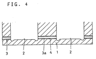
- the pipes 3 as a fluid passage are cast in the inner and outer calipers 1a and 1b.
- the calipers are cast with the pipes 3 put in position.
- the cylinder bores 2 communicate with a brake fluid supply port 10.
- Each pipe 3 includes an intermediate short pipe 3a separated from the remaining pipe portion.
- the parllelly arranged cylinder bores 2 communicate with each other through the pipe 3a provided therebetween.
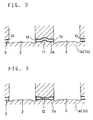
- the pipe 3a has a projection or bend 11 at its intermediate portion as shown on an enlarged scale in Fig. 2.
- an engaging portion extending in a diametric direction of the pipe is formed between the pipe 3a and the inner caliper 1a (and outer caliper 1b). This portion prevents longitudinal shift of the pipe 3a.
- Fig. 3 shows another embodiment in which the pipe 3a has a recess 12.
- an engaging portion extending in a diametric direction of the pipe 3 is formed on the pipe 3a. These portions prevent longitudinal shift of the pipe 3a.
- the recess 12 shown in Fig. 3 is formed by drawing the pipe 3a at its midportion. But such a recess or a projection may be formed in any other manner.
- two cylinders bores 2 are formed in each of the inner and outer calipers 1a, 1b.
- this invention is also equally applicable to opposed-piston type brakes having more than two cylinder bores in each of the inner and outer calipers, opposed-piston type disk brakes having one cylinder bore in one of the inner and outer calipers, and floating type disk brakes in which plurality of cylinder bores are formed in only the inner caliper.
Landscapes
- Engineering & Computer Science (AREA)
- General Engineering & Computer Science (AREA)
- Mechanical Engineering (AREA)
- Braking Arrangements (AREA)
Claims (2)
- Frein à disque du type à plusieurs pots, qui comprend un étrier (1) dans lequel sont formés plusieurs alésages cylindriques (2) parallèles les uns aux autres, plusieurs pistons (5) montés dans lesdits alésages cylindriques (2) respectifs, lesdits pistons (5) repoussant en utilisation au moins deux tampons de frottement opposés (6) en contact de frottement avec un rotor en disque, lesdits alésages cylindriques (2) communiquant les uns avec les autres par un passage pour fluide (3a) formé dans ledit étrier (1), ledit passage pour fluide (3a) étant défini par un conduit coulé dans ledit étrier (1) de manière à s'étendre entre lesdits alésages cylindriques (2) et à faire communiquer lesdits alésages cylindriques (2) les uns avec les autres,
caractérisé en ce que dans la direction diamétrale, ledit conduit (3a) présente une saillie ou un creux (11, 12) situés entre lesdits alésages cylindriques (2) de manière à être maintenu captif par ledit étrier dans le sens de sa longueur et à être immobilisé par rapport audit étrier. - Frein à disque selon la revendication 1, dans lequel les extrémités dudit conduit (3a) sont en retrait par rapport à la paroi intérieure dudit alésage cylindrique (2).
Priority Applications (1)
| Application Number | Priority Date | Filing Date | Title |
|---|---|---|---|
| EP04020844A EP1482199B1 (fr) | 1997-10-03 | 1998-10-02 | Frein à disque multicylindre |
Applications Claiming Priority (3)
| Application Number | Priority Date | Filing Date | Title |
|---|---|---|---|
| JP27159497 | 1997-10-03 | ||
| JP271594/97 | 1997-10-03 | ||
| JP27159497A JP3568752B2 (ja) | 1997-10-03 | 1997-10-03 | マルチポット型ディスクブレーキ |
Related Child Applications (1)
| Application Number | Title | Priority Date | Filing Date |
|---|---|---|---|
| EP04020844A Division EP1482199B1 (fr) | 1997-10-03 | 1998-10-02 | Frein à disque multicylindre |
Publications (3)
| Publication Number | Publication Date |
|---|---|
| EP0907034A2 EP0907034A2 (fr) | 1999-04-07 |
| EP0907034A3 EP0907034A3 (fr) | 2000-11-29 |
| EP0907034B1 true EP0907034B1 (fr) | 2006-07-19 |
Family
ID=17502259
Family Applications (2)
| Application Number | Title | Priority Date | Filing Date |
|---|---|---|---|
| EP04020844A Expired - Lifetime EP1482199B1 (fr) | 1997-10-03 | 1998-10-02 | Frein à disque multicylindre |
| EP98308049A Expired - Lifetime EP0907034B1 (fr) | 1997-10-03 | 1998-10-02 | Frein à disque multicylindre |
Family Applications Before (1)
| Application Number | Title | Priority Date | Filing Date |
|---|---|---|---|
| EP04020844A Expired - Lifetime EP1482199B1 (fr) | 1997-10-03 | 1998-10-02 | Frein à disque multicylindre |
Country Status (4)
| Country | Link |
|---|---|
| US (1) | US6092631A (fr) |
| EP (2) | EP1482199B1 (fr) |
| JP (1) | JP3568752B2 (fr) |
| DE (2) | DE69835262T2 (fr) |
Families Citing this family (15)
| Publication number | Priority date | Publication date | Assignee | Title |
|---|---|---|---|---|
| JP2005163809A (ja) * | 2003-11-28 | 2005-06-23 | Hitachi Ltd | ディスクブレーキ |
| US7249658B2 (en) * | 2004-04-22 | 2007-07-31 | Akebono | Wide caliper assembly design |
| US8672100B2 (en) * | 2005-02-07 | 2014-03-18 | Hitachi, Ltd. | Cylinder apparatus and disk brake |
| ITMI20060016A1 (it) * | 2006-01-05 | 2007-07-06 | Sunstar Logistic Singapore Pte Ltd | Metodo di fabbricazione di pinze per freni a disco perfezionato |
| JP4767889B2 (ja) * | 2007-03-27 | 2011-09-07 | 本田技研工業株式会社 | 車両用ディスクブレーキ |
| US7597178B2 (en) * | 2007-05-31 | 2009-10-06 | Ausco Products, Inc. | Caliper brake |
| JP4832402B2 (ja) * | 2007-10-22 | 2011-12-07 | 日立オートモティブシステムズ株式会社 | ディスクブレーキおよびディスクブレーキの製造方法 |
| JP4932767B2 (ja) * | 2008-03-11 | 2012-05-16 | 曙ブレーキ工業株式会社 | 対向ピストン型ディスクブレーキ用キャリパ |
| JP4883371B2 (ja) * | 2008-05-15 | 2012-02-22 | 日本軽金属株式会社 | 対向ピストン型ディスクブレーキ用キャリパ |
| US8162111B2 (en) * | 2008-12-12 | 2012-04-24 | GM Global Technology Operations LLC | Brake caliper with reduced brake squeal |
| JP4741692B2 (ja) * | 2009-06-23 | 2011-08-03 | 本田技研工業株式会社 | 対向ピストン型キャリパボディ |
| KR101353720B1 (ko) | 2011-06-23 | 2014-01-20 | 허종도 | 제동장치용 캘리퍼 |
| ITMI20120017A1 (it) | 2012-01-09 | 2013-07-10 | Freni Brembo Spa | Assieme di anima e tubo per la realizzazione di un circuito idraulico per pinza per freno a disco, corpo pinza comprendente detto assieme e metodo per la realizzazione di detto assieme e detto corpo pinza |
| GB2555578B (en) * | 2016-10-27 | 2022-05-25 | Alcon Components Ltd | Hydraulic fluid ducts for disc brake calipers and method of manufacture thereof |
| DE102022211306A1 (de) * | 2022-10-25 | 2024-04-25 | Hl Mando Corporation | Bremsflüssigkeitsführung zum leiten einer bremsflüssigkeit |
Family Cites Families (10)
| Publication number | Priority date | Publication date | Assignee | Title |
|---|---|---|---|---|
| US3261424A (en) * | 1962-01-29 | 1966-07-19 | Kaiser Gypsum Company Inc | Cellulosic fibrous sheet having fissures which are free of nonfibrous and disintegrated fibrous material |
| US3331473A (en) * | 1966-02-28 | 1967-07-18 | Kelsey Hayes Co | Disc brake with self-energized brake shoe |
| US3424276A (en) * | 1967-03-03 | 1969-01-28 | Kelsey Hayes Co | Opposed piston disk brake |
| US3882972A (en) * | 1971-06-22 | 1975-05-13 | Girling Ltd | Disc brake with identical removable friction pads |
| DE3013745C2 (de) * | 1980-04-10 | 1982-03-25 | Zahnradfabrik Friedrichshafen Ag, 7990 Friedrichshafen | Gußteil mit Kanälen, sowie Verfahren und Gießform für die Herstellung dieses Gußteils |
| JPH0292447A (ja) * | 1988-09-30 | 1990-04-03 | Nissin Kogyo Kk | ディスクブレーキ用多ポットキャリパの鋳造方法 |
| US5168964A (en) * | 1991-04-22 | 1992-12-08 | Nelson Metal Products Corporation | Brake caliper |
| JP3105068B2 (ja) | 1992-04-16 | 2000-10-30 | イズミ工業株式会社 | ブレーキキャリパの製造方法 |
| DE4430957A1 (de) * | 1994-08-31 | 1996-03-07 | Teves Gmbh Alfred | Bremssattel für Scheibenbremse |
| JPH09177843A (ja) | 1995-12-26 | 1997-07-11 | Akebono Brake Ind Co Ltd | 対向ピストン型ディスクブレーキ、およびその製造装置、並びに製造方法 |
-
1997
- 1997-10-03 JP JP27159497A patent/JP3568752B2/ja not_active Expired - Lifetime
-
1998
- 1998-10-02 DE DE69835262T patent/DE69835262T2/de not_active Expired - Lifetime
- 1998-10-02 EP EP04020844A patent/EP1482199B1/fr not_active Expired - Lifetime
- 1998-10-02 EP EP98308049A patent/EP0907034B1/fr not_active Expired - Lifetime
- 1998-10-02 DE DE69839950T patent/DE69839950D1/de not_active Expired - Lifetime
- 1998-10-05 US US09/166,091 patent/US6092631A/en not_active Expired - Lifetime
Also Published As
| Publication number | Publication date |
|---|---|
| US6092631A (en) | 2000-07-25 |
| EP1482199B1 (fr) | 2008-08-27 |
| DE69839950D1 (de) | 2008-10-09 |
| JPH11108088A (ja) | 1999-04-20 |
| DE69835262T2 (de) | 2007-06-14 |
| EP0907034A3 (fr) | 2000-11-29 |
| DE69835262D1 (de) | 2006-08-31 |
| EP0907034A2 (fr) | 1999-04-07 |
| JP3568752B2 (ja) | 2004-09-22 |
| EP1482199A1 (fr) | 2004-12-01 |
Similar Documents
| Publication | Publication Date | Title |
|---|---|---|
| EP0907034B1 (fr) | Frein à disque multicylindre | |
| EP2022999B1 (fr) | Corps de compas de frein à disque et compas de frein à disque comportant un tel corps | |
| US6116384A (en) | Disk brake | |
| JP2018533709A (ja) | ブレーキキャリパ | |
| US5386890A (en) | Disk brake having means to prevent uneven brake pad wear | |
| EP0709592B1 (fr) | Frein à disque | |
| JP3963719B2 (ja) | マルチポット型ディスクブレーキ | |
| JP2002213502A (ja) | 車両用ディスクブレーキのキャリパボディ | |
| JP2007003005A (ja) | 摺動シリンダボアを備えたキャリパ組立体 | |
| JP2000110859A (ja) | ディスクブレーキ | |
| JPS6334329B2 (fr) | ||
| JP5087497B2 (ja) | ディスクブレーキ | |
| JPS62155341A (ja) | デイスクブレ−キ | |
| JP4249065B2 (ja) | ディスクブレーキ | |
| JPH11117964A (ja) | ブレーキキャリパ | |
| JPH1130252A (ja) | 車両用ディスクブレーキの分割型キャリパ | |
| JPH0517967B2 (fr) | ||
| JP2001254768A (ja) | ディスクブレーキ | |
| JPH0224980Y2 (fr) | ||
| JPH0754670Y2 (ja) | ディスクブレーキ | |
| JPH0754669Y2 (ja) | ディスクブレーキ | |
| JPS5942505Y2 (ja) | クラツチデイスク | |
| KR940007066Y1 (ko) | 핀 슬라이드형 차량용 디스크 브레이크의 캘리퍼 보디 | |
| JPH0735828B2 (ja) | ディスクブレーキ | |
| JPH0527714Y2 (fr) |
Legal Events
| Date | Code | Title | Description |
|---|---|---|---|
| PUAI | Public reference made under article 153(3) epc to a published international application that has entered the european phase |
Free format text: ORIGINAL CODE: 0009012 |
|
| AK | Designated contracting states |
Kind code of ref document: A2 Designated state(s): DE GB |
|
| AX | Request for extension of the european patent |
Free format text: AL;LT;LV;MK;RO;SI |
|
| PUAL | Search report despatched |
Free format text: ORIGINAL CODE: 0009013 |
|
| AK | Designated contracting states |
Kind code of ref document: A3 Designated state(s): AT BE CH CY DE DK ES FI FR GB GR IE IT LI LU MC NL PT SE |
|
| AX | Request for extension of the european patent |
Free format text: AL;LT;LV;MK;RO;SI |
|
| RIC1 | Information provided on ipc code assigned before grant |
Free format text: 7F 16D 55/228 A, 7F 16D 55/22 B |
|
| 17P | Request for examination filed |
Effective date: 20010515 |
|
| AKX | Designation fees paid |
Free format text: DE GB |
|
| 17Q | First examination report despatched |
Effective date: 20040524 |
|
| GRAP | Despatch of communication of intention to grant a patent |
Free format text: ORIGINAL CODE: EPIDOSNIGR1 |
|
| GRAS | Grant fee paid |
Free format text: ORIGINAL CODE: EPIDOSNIGR3 |
|
| GRAA | (expected) grant |
Free format text: ORIGINAL CODE: 0009210 |
|
| AK | Designated contracting states |
Kind code of ref document: B1 Designated state(s): DE GB |
|
| REG | Reference to a national code |
Ref country code: GB Ref legal event code: FG4D |
|
| REF | Corresponds to: |
Ref document number: 69835262 Country of ref document: DE Date of ref document: 20060831 Kind code of ref document: P |
|
| PLBE | No opposition filed within time limit |
Free format text: ORIGINAL CODE: 0009261 |
|
| STAA | Information on the status of an ep patent application or granted ep patent |
Free format text: STATUS: NO OPPOSITION FILED WITHIN TIME LIMIT |
|
| 26N | No opposition filed |
Effective date: 20070420 |
|
| REG | Reference to a national code |
Ref country code: GB Ref legal event code: 732E |
|
| REG | Reference to a national code |
Ref country code: DE Ref legal event code: R082 Ref document number: 69835262 Country of ref document: DE Representative=s name: MEISSNER BOLTE PATENTANWAELTE RECHTSANWAELTE P, DE Ref country code: DE Ref legal event code: R082 Ref document number: 69835262 Country of ref document: DE Representative=s name: MEISSNER, BOLTE & PARTNER GBR, DE |
|
| REG | Reference to a national code |
Ref country code: DE Ref legal event code: R082 Ref document number: 69835262 Country of ref document: DE Representative=s name: MEISSNER, BOLTE & PARTNER GBR, DE |
|
| PGFP | Annual fee paid to national office [announced via postgrant information from national office to epo] |
Ref country code: GB Payment date: 20160928 Year of fee payment: 19 |
|
| PGFP | Annual fee paid to national office [announced via postgrant information from national office to epo] |
Ref country code: DE Payment date: 20160927 Year of fee payment: 19 |
|
| REG | Reference to a national code |
Ref country code: DE Ref legal event code: R119 Ref document number: 69835262 Country of ref document: DE |
|
| GBPC | Gb: european patent ceased through non-payment of renewal fee |
Effective date: 20171002 |
|
| PG25 | Lapsed in a contracting state [announced via postgrant information from national office to epo] |
Ref country code: GB Free format text: LAPSE BECAUSE OF NON-PAYMENT OF DUE FEES Effective date: 20171002 Ref country code: DE Free format text: LAPSE BECAUSE OF NON-PAYMENT OF DUE FEES Effective date: 20180501 |