EP0906847A2 - Dispositif d'entrainement pour véhicule électrique - Google Patents
Dispositif d'entrainement pour véhicule électrique Download PDFInfo
- Publication number
- EP0906847A2 EP0906847A2 EP98118321A EP98118321A EP0906847A2 EP 0906847 A2 EP0906847 A2 EP 0906847A2 EP 98118321 A EP98118321 A EP 98118321A EP 98118321 A EP98118321 A EP 98118321A EP 0906847 A2 EP0906847 A2 EP 0906847A2
- Authority
- EP
- European Patent Office
- Prior art keywords
- synchronous machine
- voltage
- drive device
- battery
- converter
- Prior art date
- Legal status (The legal status is an assumption and is not a legal conclusion. Google has not performed a legal analysis and makes no representation as to the accuracy of the status listed.)
- Withdrawn
Links
Images
Classifications
-
- B—PERFORMING OPERATIONS; TRANSPORTING
- B60—VEHICLES IN GENERAL
- B60L—PROPULSION OF ELECTRICALLY-PROPELLED VEHICLES; SUPPLYING ELECTRIC POWER FOR AUXILIARY EQUIPMENT OF ELECTRICALLY-PROPELLED VEHICLES; ELECTRODYNAMIC BRAKE SYSTEMS FOR VEHICLES IN GENERAL; MAGNETIC SUSPENSION OR LEVITATION FOR VEHICLES; MONITORING OPERATING VARIABLES OF ELECTRICALLY-PROPELLED VEHICLES; ELECTRIC SAFETY DEVICES FOR ELECTRICALLY-PROPELLED VEHICLES
- B60L15/00—Methods, circuits, or devices for controlling the traction-motor speed of electrically-propelled vehicles
- B60L15/20—Methods, circuits, or devices for controlling the traction-motor speed of electrically-propelled vehicles for control of the vehicle or its driving motor to achieve a desired performance, e.g. speed, torque, programmed variation of speed
-
- B—PERFORMING OPERATIONS; TRANSPORTING
- B60—VEHICLES IN GENERAL
- B60L—PROPULSION OF ELECTRICALLY-PROPELLED VEHICLES; SUPPLYING ELECTRIC POWER FOR AUXILIARY EQUIPMENT OF ELECTRICALLY-PROPELLED VEHICLES; ELECTRODYNAMIC BRAKE SYSTEMS FOR VEHICLES IN GENERAL; MAGNETIC SUSPENSION OR LEVITATION FOR VEHICLES; MONITORING OPERATING VARIABLES OF ELECTRICALLY-PROPELLED VEHICLES; ELECTRIC SAFETY DEVICES FOR ELECTRICALLY-PROPELLED VEHICLES
- B60L15/00—Methods, circuits, or devices for controlling the traction-motor speed of electrically-propelled vehicles
- B60L15/02—Methods, circuits, or devices for controlling the traction-motor speed of electrically-propelled vehicles characterised by the form of the current used in the control circuit
- B60L15/025—Methods, circuits, or devices for controlling the traction-motor speed of electrically-propelled vehicles characterised by the form of the current used in the control circuit using field orientation; Vector control; Direct Torque Control [DTC]
-
- B—PERFORMING OPERATIONS; TRANSPORTING
- B60—VEHICLES IN GENERAL
- B60L—PROPULSION OF ELECTRICALLY-PROPELLED VEHICLES; SUPPLYING ELECTRIC POWER FOR AUXILIARY EQUIPMENT OF ELECTRICALLY-PROPELLED VEHICLES; ELECTRODYNAMIC BRAKE SYSTEMS FOR VEHICLES IN GENERAL; MAGNETIC SUSPENSION OR LEVITATION FOR VEHICLES; MONITORING OPERATING VARIABLES OF ELECTRICALLY-PROPELLED VEHICLES; ELECTRIC SAFETY DEVICES FOR ELECTRICALLY-PROPELLED VEHICLES
- B60L50/00—Electric propulsion with power supplied within the vehicle
- B60L50/10—Electric propulsion with power supplied within the vehicle using propulsion power supplied by engine-driven generators, e.g. generators driven by combustion engines
- B60L50/16—Electric propulsion with power supplied within the vehicle using propulsion power supplied by engine-driven generators, e.g. generators driven by combustion engines with provision for separate direct mechanical propulsion
-
- B—PERFORMING OPERATIONS; TRANSPORTING
- B60—VEHICLES IN GENERAL
- B60L—PROPULSION OF ELECTRICALLY-PROPELLED VEHICLES; SUPPLYING ELECTRIC POWER FOR AUXILIARY EQUIPMENT OF ELECTRICALLY-PROPELLED VEHICLES; ELECTRODYNAMIC BRAKE SYSTEMS FOR VEHICLES IN GENERAL; MAGNETIC SUSPENSION OR LEVITATION FOR VEHICLES; MONITORING OPERATING VARIABLES OF ELECTRICALLY-PROPELLED VEHICLES; ELECTRIC SAFETY DEVICES FOR ELECTRICALLY-PROPELLED VEHICLES
- B60L50/00—Electric propulsion with power supplied within the vehicle
- B60L50/50—Electric propulsion with power supplied within the vehicle using propulsion power supplied by batteries or fuel cells
- B60L50/51—Electric propulsion with power supplied within the vehicle using propulsion power supplied by batteries or fuel cells characterised by AC-motors
-
- B—PERFORMING OPERATIONS; TRANSPORTING
- B60—VEHICLES IN GENERAL
- B60L—PROPULSION OF ELECTRICALLY-PROPELLED VEHICLES; SUPPLYING ELECTRIC POWER FOR AUXILIARY EQUIPMENT OF ELECTRICALLY-PROPELLED VEHICLES; ELECTRODYNAMIC BRAKE SYSTEMS FOR VEHICLES IN GENERAL; MAGNETIC SUSPENSION OR LEVITATION FOR VEHICLES; MONITORING OPERATING VARIABLES OF ELECTRICALLY-PROPELLED VEHICLES; ELECTRIC SAFETY DEVICES FOR ELECTRICALLY-PROPELLED VEHICLES
- B60L2220/00—Electrical machine types; Structures or applications thereof
- B60L2220/10—Electrical machine types
- B60L2220/14—Synchronous machines
-
- Y—GENERAL TAGGING OF NEW TECHNOLOGICAL DEVELOPMENTS; GENERAL TAGGING OF CROSS-SECTIONAL TECHNOLOGIES SPANNING OVER SEVERAL SECTIONS OF THE IPC; TECHNICAL SUBJECTS COVERED BY FORMER USPC CROSS-REFERENCE ART COLLECTIONS [XRACs] AND DIGESTS
- Y02—TECHNOLOGIES OR APPLICATIONS FOR MITIGATION OR ADAPTATION AGAINST CLIMATE CHANGE
- Y02T—CLIMATE CHANGE MITIGATION TECHNOLOGIES RELATED TO TRANSPORTATION
- Y02T10/00—Road transport of goods or passengers
- Y02T10/60—Other road transportation technologies with climate change mitigation effect
- Y02T10/64—Electric machine technologies in electromobility
-
- Y—GENERAL TAGGING OF NEW TECHNOLOGICAL DEVELOPMENTS; GENERAL TAGGING OF CROSS-SECTIONAL TECHNOLOGIES SPANNING OVER SEVERAL SECTIONS OF THE IPC; TECHNICAL SUBJECTS COVERED BY FORMER USPC CROSS-REFERENCE ART COLLECTIONS [XRACs] AND DIGESTS
- Y02—TECHNOLOGIES OR APPLICATIONS FOR MITIGATION OR ADAPTATION AGAINST CLIMATE CHANGE
- Y02T—CLIMATE CHANGE MITIGATION TECHNOLOGIES RELATED TO TRANSPORTATION
- Y02T10/00—Road transport of goods or passengers
- Y02T10/60—Other road transportation technologies with climate change mitigation effect
- Y02T10/70—Energy storage systems for electromobility, e.g. batteries
-
- Y—GENERAL TAGGING OF NEW TECHNOLOGICAL DEVELOPMENTS; GENERAL TAGGING OF CROSS-SECTIONAL TECHNOLOGIES SPANNING OVER SEVERAL SECTIONS OF THE IPC; TECHNICAL SUBJECTS COVERED BY FORMER USPC CROSS-REFERENCE ART COLLECTIONS [XRACs] AND DIGESTS
- Y02—TECHNOLOGIES OR APPLICATIONS FOR MITIGATION OR ADAPTATION AGAINST CLIMATE CHANGE
- Y02T—CLIMATE CHANGE MITIGATION TECHNOLOGIES RELATED TO TRANSPORTATION
- Y02T10/00—Road transport of goods or passengers
- Y02T10/60—Other road transportation technologies with climate change mitigation effect
- Y02T10/7072—Electromobility specific charging systems or methods for batteries, ultracapacitors, supercapacitors or double-layer capacitors
-
- Y—GENERAL TAGGING OF NEW TECHNOLOGICAL DEVELOPMENTS; GENERAL TAGGING OF CROSS-SECTIONAL TECHNOLOGIES SPANNING OVER SEVERAL SECTIONS OF THE IPC; TECHNICAL SUBJECTS COVERED BY FORMER USPC CROSS-REFERENCE ART COLLECTIONS [XRACs] AND DIGESTS
- Y02—TECHNOLOGIES OR APPLICATIONS FOR MITIGATION OR ADAPTATION AGAINST CLIMATE CHANGE
- Y02T—CLIMATE CHANGE MITIGATION TECHNOLOGIES RELATED TO TRANSPORTATION
- Y02T10/00—Road transport of goods or passengers
- Y02T10/60—Other road transportation technologies with climate change mitigation effect
- Y02T10/72—Electric energy management in electromobility
Definitions
- the invention relates to a drive device for an electric vehicle according to claim 1; such a drive device finds application both in vehicles with sole Electric motor drive as well as in hybrid vehicles alternate or parallel drive by an electric motor or by an internal combustion engine.
- the object of the present invention is to optimize the range for an electric vehicle with a battery Electric motor due to lower operational load this battery. This task is solved by a Drive device according to claim 1; advantageous embodiments the invention are the subject of the dependent claims.
- the drive device can be advantageous Way at least in some areas of idle operation of the electric motor by locking according to the invention the circuit breaker due to the deactivation of the converter to an end of charge of the battery for the purpose of Adjustment of a zero torque with appropriate timing the motor phase currents are dispensed with.
- the circuit breaker is blocked under the aforementioned conditions is included in electric vehicles with electric motors variable field, i.e. especially with asynchronous machines or separately excited synchronous machines, in an advantageous manner possible over the entire speed range.
- the drive device according to the invention When operating an electric vehicle with one regarding simple structure with particularly advantageous synchronous machine permanently excited rotor can by the drive device according to the invention moreover an uncontrolled, if necessary current flow leading to damage to the battery the battery can be prevented in the event that the permanent magnet rotor flux induced terminal voltage of the synchronous machine, especially when operating in the field weakening area, becomes too high and therefore the rectified regenerative direct voltage or DC link voltage on the battery side Output of the converter the parallel battery voltage inadmissible.
- the device according to the invention allows thus with little effort in terms of circuitry range optimization with simultaneous battery protection in the case of a drive device using a permanent magnet synchronous machine as an electrical drive part.
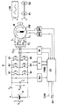
- the drawing shows a synchronous machine M with a permanent magnetic rotor PM fed from a battery B with the battery voltage U B and the battery current I B via a converter U with a parallel intermediate circuit capacitor C and with six circuit breakers B1-B6 in a conventional three-phase bridge circuit.
- the permanently excited synchronous machine M can be coupled with its output shaft either alternately or at the same time rigidly to an internal combustion engine VB or to a vehicle wheel set R1 / R2 of an electric vehicle.
- the following considerations relate in particular the idle operation of the synchronous machine designed according to the invention, i.e. to the area in which the setpoint for the torque-generating motor current is zero.
- the circuit breakers B1-B6 are activated and thus clocked or deactivated in a controlled manner and thus blocked via a control unit CB, which is dependent on the control or regulation via a power stage T with the circuit breakers B1-B6 of the converter U.
- the control unit CB which is fed from a direct voltage source UV, receives the motor currents I 1 ; I 2 ; I 3 of the synchronous machine M via a current measuring device MI, the actual values of the rotor speed of the synchronous machine M via a speed measuring device MR and a voltage measuring device MU at the battery-side output of the converter U applied regenerative DC voltage or DC link voltage U ZW supplied.
- the control unit calculates the automatic determination of the operating point at which, in the idle mode considered according to the invention, the circuit breakers B1-B6 and thus the battery discharge protection of the battery B are switched to the activation of the circuit breakers B1-B6 and thus the battery overcharge protection CB, based on the rotor speed of the synchronous machine M and the known actual flux value of the synchronous machine M, the induced motor terminal voltages U K12 ; U K23 ; U K31 between the winding terminals of the synchronous machine M; From this, the regenerative DC voltage or DC link voltage U ZW which is rectified by their free-wheeling diodes when the circuit breakers B1-B6 are deactivated, ie blocked, is taken into account, if necessary, taking into account the voltage drops in the converter U. If this theoretical intermediate circuit voltage U ZW exceeds the battery voltage U B , there could be an uncontrolled current flow I B from the synchronous machine M to the battery UB and there is a risk of damage to the battery B.
- a magnetizing current can be impressed on the permanently excited synchronous machine M with such control of the current phase position that the induced terminal voltages U K12 ; U K23 ; U K31 and thus the regenerative direct voltage or intermediate circuit voltage U ZW can be reduced and undesired recharging of the battery B can be avoided.
- appropriate regulation of the magnetization current ensures that no current I B flows into the battery B and the latter is not overcharged.
- the necessary increase in the magnetization current is synonymous with a change in the current phase position, i.e. the phase position of the motor current compared to the induced terminal voltage of the synchronous machine M.
- the circuit breakers B1-B6 are activated simultaneously with the specification of a voltage vector defined in phase position and amplitude, so that compensating processes be avoided in the drive.
- the idle mode of the synchronous machine is to be left without a torque request and with a correspondingly inactivated converter and a reactivation is provided, for example for the purpose of accelerating from the idle driving state of the electric vehicle, then according to one embodiment of the invention, by specifying a corresponding field-oriented regulated voltage pointer u 1 for the stator winding of the synchronous machine M, depending on their instantaneous rotor speed and their instantaneous position of the rotor field axis, inadmissibly high currents and thus undesirable torque surges can be avoided.
- and the angle ⁇ 1 of the voltage vector u 1 is expediently carried out by pulse width modulation control of the circuit breakers B1-B6 in accordance with the space vector modulation known per se via the control unit CB with corresponding control outputs PWM.
- the voltage pointer u 1 to be set in each case via the reactivated circuit breakers B1-B6 and to be applied to the machine terminals of the synchronous machine M is defined in each case as a function of a current setpoint, for example given by the position of the accelerator pedal, and the instantaneous value, for example via a motor speed sensor MR and one Motor position transmitter MP, recorded values of the rotor speed ⁇ R and the rotor field angle ⁇ R.
- the amount u 1 of the voltage pointer to be applied when the circuit breakers B1-B6 are reactivated is advantageously determined from a stored model of the synchronous machine M.
- the voltage amount is added from the induced voltage of the synchronous machine and the voltage drops across the stator resistance and stator inductance.
- the induced voltage of the machine results from the multiplication of the measured rotor speed ⁇ R by the rotor flux ⁇ rotor and the number of pole pairs p.
- the voltage drop across the stator resistance is calculated by multiplying the stator current setpoint i 1set and the stator resistance R 1 .
- the voltage drop at the stator inductance is obtained by multiplying the stator current setpoint i 1set , the stator inductance L ⁇ and the electrical rotational frequency ⁇ 1.
- a machine model is advantageously used that contains the stator voltage components in the d-axis (field-forming axis) and in the q-axis (torque-forming axis ) advantageously determined.
- u 1q R 1 ⁇ I 1q should + L ⁇ ⁇ ⁇ 1 ⁇ I 1d should + ⁇ R ⁇ P ⁇ ⁇ rotor
- u 1d R 1 ⁇ I 1d should + L ⁇ ⁇ ⁇ 1 ⁇ I 1q should
- the angle ⁇ 1 of the voltage pointer to be applied when the circuit breakers B1-B6 are reactivated is advantageously derived directly from the values of the motor position transmitter MP.
- the circuit breakers B1-B6 have to be reactivated at a time when, for example, due to a lack of resolution of the encoder, there is no exact angular position, the current angular position must be estimated.
- the angular position ⁇ R is extrapolated from the last encoder information. The extrapolation is carried out using the last angular position received from the encoder, the time difference to the last encoder information and the current rotor speed. An advantageous embodiment of this extrapolation calculation also includes the current rotor acceleration.
- the aforementioned determination of the rotor angle ⁇ R now provides the position of the d-axis (field-forming axis) of the field-oriented coordinate system.
- the angle of the voltage pointer to be set is obtained by adding the angle ⁇ u spanned by the two voltage components u 1d and U 1q to the measured position of the ⁇ R d axis.
- ⁇ 1 ⁇ R + ⁇ u
- ⁇ u arc tan u d u q
Landscapes
- Engineering & Computer Science (AREA)
- Power Engineering (AREA)
- Transportation (AREA)
- Mechanical Engineering (AREA)
- Life Sciences & Earth Sciences (AREA)
- Sustainable Development (AREA)
- Sustainable Energy (AREA)
- Control Of Ac Motors In General (AREA)
Applications Claiming Priority (4)
| Application Number | Priority Date | Filing Date | Title |
|---|---|---|---|
| DE19743757 | 1997-10-02 | ||
| DE19743757A DE19743757A1 (de) | 1997-10-02 | 1997-10-02 | Antriebsvorrichtung für ein Elektrofahrzeug |
| DE29815331U DE29815331U1 (de) | 1998-08-26 | 1998-08-26 | Antriebsvorrichtung für ein Elektrofahrzeug |
| DE29815331U | 1998-08-26 |
Publications (2)
| Publication Number | Publication Date |
|---|---|
| EP0906847A2 true EP0906847A2 (fr) | 1999-04-07 |
| EP0906847A3 EP0906847A3 (fr) | 2001-08-08 |
Family
ID=26040553
Family Applications (1)
| Application Number | Title | Priority Date | Filing Date |
|---|---|---|---|
| EP98118321A Withdrawn EP0906847A3 (fr) | 1997-10-02 | 1998-09-28 | Dispositif d'entrainement pour véhicule électrique |
Country Status (1)
| Country | Link |
|---|---|
| EP (1) | EP0906847A3 (fr) |
Cited By (7)
| Publication number | Priority date | Publication date | Assignee | Title |
|---|---|---|---|---|
| US6333620B1 (en) | 2000-09-15 | 2001-12-25 | Transportation Techniques Llc | Method and apparatus for adaptively controlling a state of charge of a battery array of a series type hybrid electric vehicle |
| US6469403B2 (en) * | 2000-04-06 | 2002-10-22 | Suzuki Motor Corporation | Control apparatus for hybrid vehicle |
| US6483198B2 (en) | 2001-01-19 | 2002-11-19 | Transportation Techniques Llc | Hybrid electric vehicle having a selective zero emission mode, and method of selectively operating the zero emission mode |
| US6573675B2 (en) | 2000-12-27 | 2003-06-03 | Transportation Techniques Llc | Method and apparatus for adaptive energy control of hybrid electric vehicle propulsion |
| US6622804B2 (en) | 2001-01-19 | 2003-09-23 | Transportation Techniques, Llc. | Hybrid electric vehicle and method of selectively operating the hybrid electric vehicle |
| US7071642B2 (en) | 2000-12-27 | 2006-07-04 | Transportation Techniques, Llc | Method and apparatus for adaptive control of traction drive units in a hybrid vehicle |
| US7122979B2 (en) | 2000-12-27 | 2006-10-17 | Transportation Techniques, Llc | Method and apparatus for selective operation of a hybrid electric vehicle in various driving modes |
Family Cites Families (3)
| Publication number | Priority date | Publication date | Assignee | Title |
|---|---|---|---|---|
| JP2935479B2 (ja) * | 1991-03-08 | 1999-08-16 | 本田技研工業株式会社 | 永久磁石式同期モータおよびモータシステム |
| DE4324010C2 (de) * | 1993-07-17 | 1995-05-11 | Daimler Benz Ag | Verfahren zur Steuerung der Drehmomentabgabe eines ein Fahrzeug antreibenden Hybridantriebes |
| DE69416747T2 (de) * | 1993-08-10 | 1999-07-29 | Toyota Jidosha K.K., Toyota, Aichi | Vorrichtung zum Antrieb und zur Steuerung von Synchronmotoren, die Permanentmagnete als Erregungssystem benützen |
-
1998
- 1998-09-28 EP EP98118321A patent/EP0906847A3/fr not_active Withdrawn
Cited By (11)
| Publication number | Priority date | Publication date | Assignee | Title |
|---|---|---|---|---|
| US6469403B2 (en) * | 2000-04-06 | 2002-10-22 | Suzuki Motor Corporation | Control apparatus for hybrid vehicle |
| US6333620B1 (en) | 2000-09-15 | 2001-12-25 | Transportation Techniques Llc | Method and apparatus for adaptively controlling a state of charge of a battery array of a series type hybrid electric vehicle |
| US6573675B2 (en) | 2000-12-27 | 2003-06-03 | Transportation Techniques Llc | Method and apparatus for adaptive energy control of hybrid electric vehicle propulsion |
| US6897629B2 (en) | 2000-12-27 | 2005-05-24 | Transportation Techniques, Llc | Method and apparatus for adaptive control and protection of hybrid electric vehicle systems |
| US7071642B2 (en) | 2000-12-27 | 2006-07-04 | Transportation Techniques, Llc | Method and apparatus for adaptive control of traction drive units in a hybrid vehicle |
| US7122979B2 (en) | 2000-12-27 | 2006-10-17 | Transportation Techniques, Llc | Method and apparatus for selective operation of a hybrid electric vehicle in various driving modes |
| US6483198B2 (en) | 2001-01-19 | 2002-11-19 | Transportation Techniques Llc | Hybrid electric vehicle having a selective zero emission mode, and method of selectively operating the zero emission mode |
| US6622804B2 (en) | 2001-01-19 | 2003-09-23 | Transportation Techniques, Llc. | Hybrid electric vehicle and method of selectively operating the hybrid electric vehicle |
| US6877576B2 (en) | 2001-01-19 | 2005-04-12 | Transportation Techniques, Llc. | Method and apparatus for selective operation of a hybrid electric vehicle powerplant |
| US7017542B2 (en) | 2001-01-19 | 2006-03-28 | Transportation Techniques, Llc | Hybrid electric vehicle and method of selectively operating the hybrid electric vehicle |
| US7121234B2 (en) | 2001-01-19 | 2006-10-17 | Transportation Techniques, Llc | Hybrid electric vehicle and method of selectively operating the hybrid electric vehicle |
Also Published As
| Publication number | Publication date |
|---|---|
| EP0906847A3 (fr) | 2001-08-08 |
Similar Documents
| Publication | Publication Date | Title |
|---|---|---|
| US11177760B2 (en) | Electric motor apparatus | |
| DE69416747T2 (de) | Vorrichtung zum Antrieb und zur Steuerung von Synchronmotoren, die Permanentmagnete als Erregungssystem benützen | |
| DE69919065T2 (de) | Antriebsregelvorrichtung für eine elektrische Synchronmaschine mit Feldwicklung | |
| DE102009015318B4 (de) | Leistungssystem für ein Hybridelektrokraftfahrzeug (HEV) | |
| EP2822807B1 (fr) | Véhicule pourvu d'un moteur électrique et procédé permettant de faire fonctionner ledit moteur | |
| DE102013217619B4 (de) | System und Verfahren zum Implementieren eines Abhilfe schaffenden elektrischen Kurzschlusses | |
| DE102020205292A1 (de) | Eine Elektromotorvorrichtung | |
| DE102015117813B4 (de) | Steuerungseinheit und Steuerungsverfahren für rotierende elektrische Maschine | |
| DE112009001975T5 (de) | Sensorlose Motorsteuervorrichtung | |
| DE112007000033T5 (de) | Elektrisches Antriebssteuerungsgerät und elektrisches Antriebssteuerungsverfahren | |
| DE19722175A1 (de) | Antriebssystem für ein elektrisches Fahrzeug | |
| DE102014100445A1 (de) | Vorrichtung zum Steuern einer drehenden Maschine mit Mehrfachwicklung | |
| WO2008138864A1 (fr) | Procédé et dispositif de fonctionnement d'une unité de commande pour commander une machine électrique | |
| DE112007000286T5 (de) | Elektromotorantriebs-Steuerungsverfahren und -gerät | |
| DE112020005338T5 (de) | Wechselrichtersteuervorrichtung und elektrofahrzeugsystem | |
| DE102011000949A1 (de) | Steuervorrichtung für eine drehende elektrische Maschine | |
| DE112020003588T5 (de) | Wechselrichter-Steuervorrichtung | |
| DE112021001533T5 (de) | Motorsteuervorrichtung, elektromechanische einheit, elektrofahrzeugsystem und motorsteuerverfahren | |
| DE102011003372A1 (de) | Dual source automotive propulsion system and method of operation | |
| DE102011002466A1 (de) | Verfahren und System zum Betreiben eines Elektromotors | |
| DE102017205328A1 (de) | Steuergerät einer Drehelektromaschine | |
| DE102014114122A1 (de) | Drehende elektrische Maschine, die an einem Fahrzeug befestigt ist | |
| DE112021005439T5 (de) | Motorsteuerungsvorrichtung, elektromechanische integrierte einheit, aufwärtswandlersystem, elektrofahrzeugsystem, und motorsteuerungsverfahren | |
| DE10347208B4 (de) | Betriebssteuervorrichtung für einen Elektromotor und sein Steuerverfahren | |
| AT522014B1 (de) | Verfahren für den Notbetrieb einer Umrichterschalteinheit und zugehöriges Fahrzeug |
Legal Events
| Date | Code | Title | Description |
|---|---|---|---|
| PUAI | Public reference made under article 153(3) epc to a published international application that has entered the european phase |
Free format text: ORIGINAL CODE: 0009012 |
|
| AK | Designated contracting states |
Kind code of ref document: A2 Designated state(s): DE FR IT |
|
| AX | Request for extension of the european patent |
Free format text: AL;LT;LV;MK;RO;SI |
|
| PUAL | Search report despatched |
Free format text: ORIGINAL CODE: 0009013 |
|
| AK | Designated contracting states |
Kind code of ref document: A3 Designated state(s): AT BE CH CY DE DK ES FI FR GB GR IE IT LI LU MC NL PT SE |
|
| AX | Request for extension of the european patent |
Free format text: AL;LT;LV;MK;RO;SI |
|
| 17P | Request for examination filed |
Effective date: 20010910 |
|
| AKX | Designation fees paid |
Free format text: DE FR IT |
|
| 17Q | First examination report despatched |
Effective date: 20071107 |
|
| RAP1 | Party data changed (applicant data changed or rights of an application transferred) |
Owner name: CONTINENTAL AUTOMOTIVE GMBH |
|
| STAA | Information on the status of an ep patent application or granted ep patent |
Free format text: STATUS: THE APPLICATION HAS BEEN WITHDRAWN |
|
| 18W | Application withdrawn |
Effective date: 20091009 |