EP0906847A2 - Drive device for an electric vehicle - Google Patents
Drive device for an electric vehicle Download PDFInfo
- Publication number
- EP0906847A2 EP0906847A2 EP98118321A EP98118321A EP0906847A2 EP 0906847 A2 EP0906847 A2 EP 0906847A2 EP 98118321 A EP98118321 A EP 98118321A EP 98118321 A EP98118321 A EP 98118321A EP 0906847 A2 EP0906847 A2 EP 0906847A2
- Authority
- EP
- European Patent Office
- Prior art keywords
- synchronous machine
- voltage
- drive device
- battery
- converter
- Prior art date
- Legal status (The legal status is an assumption and is not a legal conclusion. Google has not performed a legal analysis and makes no representation as to the accuracy of the status listed.)
- Withdrawn
Links
Images
Classifications
-
- B—PERFORMING OPERATIONS; TRANSPORTING
- B60—VEHICLES IN GENERAL
- B60L—PROPULSION OF ELECTRICALLY-PROPELLED VEHICLES; SUPPLYING ELECTRIC POWER FOR AUXILIARY EQUIPMENT OF ELECTRICALLY-PROPELLED VEHICLES; ELECTRODYNAMIC BRAKE SYSTEMS FOR VEHICLES IN GENERAL; MAGNETIC SUSPENSION OR LEVITATION FOR VEHICLES; MONITORING OPERATING VARIABLES OF ELECTRICALLY-PROPELLED VEHICLES; ELECTRIC SAFETY DEVICES FOR ELECTRICALLY-PROPELLED VEHICLES
- B60L15/00—Methods, circuits, or devices for controlling the traction-motor speed of electrically-propelled vehicles
- B60L15/20—Methods, circuits, or devices for controlling the traction-motor speed of electrically-propelled vehicles for control of the vehicle or its driving motor to achieve a desired performance, e.g. speed, torque, programmed variation of speed
-
- B—PERFORMING OPERATIONS; TRANSPORTING
- B60—VEHICLES IN GENERAL
- B60L—PROPULSION OF ELECTRICALLY-PROPELLED VEHICLES; SUPPLYING ELECTRIC POWER FOR AUXILIARY EQUIPMENT OF ELECTRICALLY-PROPELLED VEHICLES; ELECTRODYNAMIC BRAKE SYSTEMS FOR VEHICLES IN GENERAL; MAGNETIC SUSPENSION OR LEVITATION FOR VEHICLES; MONITORING OPERATING VARIABLES OF ELECTRICALLY-PROPELLED VEHICLES; ELECTRIC SAFETY DEVICES FOR ELECTRICALLY-PROPELLED VEHICLES
- B60L15/00—Methods, circuits, or devices for controlling the traction-motor speed of electrically-propelled vehicles
- B60L15/02—Methods, circuits, or devices for controlling the traction-motor speed of electrically-propelled vehicles characterised by the form of the current used in the control circuit
- B60L15/025—Methods, circuits, or devices for controlling the traction-motor speed of electrically-propelled vehicles characterised by the form of the current used in the control circuit using field orientation; Vector control; Direct Torque Control [DTC]
-
- B—PERFORMING OPERATIONS; TRANSPORTING
- B60—VEHICLES IN GENERAL
- B60L—PROPULSION OF ELECTRICALLY-PROPELLED VEHICLES; SUPPLYING ELECTRIC POWER FOR AUXILIARY EQUIPMENT OF ELECTRICALLY-PROPELLED VEHICLES; ELECTRODYNAMIC BRAKE SYSTEMS FOR VEHICLES IN GENERAL; MAGNETIC SUSPENSION OR LEVITATION FOR VEHICLES; MONITORING OPERATING VARIABLES OF ELECTRICALLY-PROPELLED VEHICLES; ELECTRIC SAFETY DEVICES FOR ELECTRICALLY-PROPELLED VEHICLES
- B60L50/00—Electric propulsion with power supplied within the vehicle
- B60L50/10—Electric propulsion with power supplied within the vehicle using propulsion power supplied by engine-driven generators, e.g. generators driven by combustion engines
- B60L50/16—Electric propulsion with power supplied within the vehicle using propulsion power supplied by engine-driven generators, e.g. generators driven by combustion engines with provision for separate direct mechanical propulsion
-
- B—PERFORMING OPERATIONS; TRANSPORTING
- B60—VEHICLES IN GENERAL
- B60L—PROPULSION OF ELECTRICALLY-PROPELLED VEHICLES; SUPPLYING ELECTRIC POWER FOR AUXILIARY EQUIPMENT OF ELECTRICALLY-PROPELLED VEHICLES; ELECTRODYNAMIC BRAKE SYSTEMS FOR VEHICLES IN GENERAL; MAGNETIC SUSPENSION OR LEVITATION FOR VEHICLES; MONITORING OPERATING VARIABLES OF ELECTRICALLY-PROPELLED VEHICLES; ELECTRIC SAFETY DEVICES FOR ELECTRICALLY-PROPELLED VEHICLES
- B60L50/00—Electric propulsion with power supplied within the vehicle
- B60L50/50—Electric propulsion with power supplied within the vehicle using propulsion power supplied by batteries or fuel cells
- B60L50/51—Electric propulsion with power supplied within the vehicle using propulsion power supplied by batteries or fuel cells characterised by AC-motors
-
- B—PERFORMING OPERATIONS; TRANSPORTING
- B60—VEHICLES IN GENERAL
- B60L—PROPULSION OF ELECTRICALLY-PROPELLED VEHICLES; SUPPLYING ELECTRIC POWER FOR AUXILIARY EQUIPMENT OF ELECTRICALLY-PROPELLED VEHICLES; ELECTRODYNAMIC BRAKE SYSTEMS FOR VEHICLES IN GENERAL; MAGNETIC SUSPENSION OR LEVITATION FOR VEHICLES; MONITORING OPERATING VARIABLES OF ELECTRICALLY-PROPELLED VEHICLES; ELECTRIC SAFETY DEVICES FOR ELECTRICALLY-PROPELLED VEHICLES
- B60L2220/00—Electrical machine types; Structures or applications thereof
- B60L2220/10—Electrical machine types
- B60L2220/14—Synchronous machines
-
- Y—GENERAL TAGGING OF NEW TECHNOLOGICAL DEVELOPMENTS; GENERAL TAGGING OF CROSS-SECTIONAL TECHNOLOGIES SPANNING OVER SEVERAL SECTIONS OF THE IPC; TECHNICAL SUBJECTS COVERED BY FORMER USPC CROSS-REFERENCE ART COLLECTIONS [XRACs] AND DIGESTS
- Y02—TECHNOLOGIES OR APPLICATIONS FOR MITIGATION OR ADAPTATION AGAINST CLIMATE CHANGE
- Y02T—CLIMATE CHANGE MITIGATION TECHNOLOGIES RELATED TO TRANSPORTATION
- Y02T10/00—Road transport of goods or passengers
- Y02T10/60—Other road transportation technologies with climate change mitigation effect
- Y02T10/64—Electric machine technologies in electromobility
-
- Y—GENERAL TAGGING OF NEW TECHNOLOGICAL DEVELOPMENTS; GENERAL TAGGING OF CROSS-SECTIONAL TECHNOLOGIES SPANNING OVER SEVERAL SECTIONS OF THE IPC; TECHNICAL SUBJECTS COVERED BY FORMER USPC CROSS-REFERENCE ART COLLECTIONS [XRACs] AND DIGESTS
- Y02—TECHNOLOGIES OR APPLICATIONS FOR MITIGATION OR ADAPTATION AGAINST CLIMATE CHANGE
- Y02T—CLIMATE CHANGE MITIGATION TECHNOLOGIES RELATED TO TRANSPORTATION
- Y02T10/00—Road transport of goods or passengers
- Y02T10/60—Other road transportation technologies with climate change mitigation effect
- Y02T10/70—Energy storage systems for electromobility, e.g. batteries
-
- Y—GENERAL TAGGING OF NEW TECHNOLOGICAL DEVELOPMENTS; GENERAL TAGGING OF CROSS-SECTIONAL TECHNOLOGIES SPANNING OVER SEVERAL SECTIONS OF THE IPC; TECHNICAL SUBJECTS COVERED BY FORMER USPC CROSS-REFERENCE ART COLLECTIONS [XRACs] AND DIGESTS
- Y02—TECHNOLOGIES OR APPLICATIONS FOR MITIGATION OR ADAPTATION AGAINST CLIMATE CHANGE
- Y02T—CLIMATE CHANGE MITIGATION TECHNOLOGIES RELATED TO TRANSPORTATION
- Y02T10/00—Road transport of goods or passengers
- Y02T10/60—Other road transportation technologies with climate change mitigation effect
- Y02T10/7072—Electromobility specific charging systems or methods for batteries, ultracapacitors, supercapacitors or double-layer capacitors
-
- Y—GENERAL TAGGING OF NEW TECHNOLOGICAL DEVELOPMENTS; GENERAL TAGGING OF CROSS-SECTIONAL TECHNOLOGIES SPANNING OVER SEVERAL SECTIONS OF THE IPC; TECHNICAL SUBJECTS COVERED BY FORMER USPC CROSS-REFERENCE ART COLLECTIONS [XRACs] AND DIGESTS
- Y02—TECHNOLOGIES OR APPLICATIONS FOR MITIGATION OR ADAPTATION AGAINST CLIMATE CHANGE
- Y02T—CLIMATE CHANGE MITIGATION TECHNOLOGIES RELATED TO TRANSPORTATION
- Y02T10/00—Road transport of goods or passengers
- Y02T10/60—Other road transportation technologies with climate change mitigation effect
- Y02T10/72—Electric energy management in electromobility
Definitions
- the invention relates to a drive device for an electric vehicle according to claim 1; such a drive device finds application both in vehicles with sole Electric motor drive as well as in hybrid vehicles alternate or parallel drive by an electric motor or by an internal combustion engine.
- the object of the present invention is to optimize the range for an electric vehicle with a battery Electric motor due to lower operational load this battery. This task is solved by a Drive device according to claim 1; advantageous embodiments the invention are the subject of the dependent claims.
- the drive device can be advantageous Way at least in some areas of idle operation of the electric motor by locking according to the invention the circuit breaker due to the deactivation of the converter to an end of charge of the battery for the purpose of Adjustment of a zero torque with appropriate timing the motor phase currents are dispensed with.
- the circuit breaker is blocked under the aforementioned conditions is included in electric vehicles with electric motors variable field, i.e. especially with asynchronous machines or separately excited synchronous machines, in an advantageous manner possible over the entire speed range.
- the drive device according to the invention When operating an electric vehicle with one regarding simple structure with particularly advantageous synchronous machine permanently excited rotor can by the drive device according to the invention moreover an uncontrolled, if necessary current flow leading to damage to the battery the battery can be prevented in the event that the permanent magnet rotor flux induced terminal voltage of the synchronous machine, especially when operating in the field weakening area, becomes too high and therefore the rectified regenerative direct voltage or DC link voltage on the battery side Output of the converter the parallel battery voltage inadmissible.
- the device according to the invention allows thus with little effort in terms of circuitry range optimization with simultaneous battery protection in the case of a drive device using a permanent magnet synchronous machine as an electrical drive part.
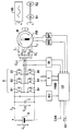
- the drawing shows a synchronous machine M with a permanent magnetic rotor PM fed from a battery B with the battery voltage U B and the battery current I B via a converter U with a parallel intermediate circuit capacitor C and with six circuit breakers B1-B6 in a conventional three-phase bridge circuit.
- the permanently excited synchronous machine M can be coupled with its output shaft either alternately or at the same time rigidly to an internal combustion engine VB or to a vehicle wheel set R1 / R2 of an electric vehicle.
- the following considerations relate in particular the idle operation of the synchronous machine designed according to the invention, i.e. to the area in which the setpoint for the torque-generating motor current is zero.
- the circuit breakers B1-B6 are activated and thus clocked or deactivated in a controlled manner and thus blocked via a control unit CB, which is dependent on the control or regulation via a power stage T with the circuit breakers B1-B6 of the converter U.
- the control unit CB which is fed from a direct voltage source UV, receives the motor currents I 1 ; I 2 ; I 3 of the synchronous machine M via a current measuring device MI, the actual values of the rotor speed of the synchronous machine M via a speed measuring device MR and a voltage measuring device MU at the battery-side output of the converter U applied regenerative DC voltage or DC link voltage U ZW supplied.
- the control unit calculates the automatic determination of the operating point at which, in the idle mode considered according to the invention, the circuit breakers B1-B6 and thus the battery discharge protection of the battery B are switched to the activation of the circuit breakers B1-B6 and thus the battery overcharge protection CB, based on the rotor speed of the synchronous machine M and the known actual flux value of the synchronous machine M, the induced motor terminal voltages U K12 ; U K23 ; U K31 between the winding terminals of the synchronous machine M; From this, the regenerative DC voltage or DC link voltage U ZW which is rectified by their free-wheeling diodes when the circuit breakers B1-B6 are deactivated, ie blocked, is taken into account, if necessary, taking into account the voltage drops in the converter U. If this theoretical intermediate circuit voltage U ZW exceeds the battery voltage U B , there could be an uncontrolled current flow I B from the synchronous machine M to the battery UB and there is a risk of damage to the battery B.
- a magnetizing current can be impressed on the permanently excited synchronous machine M with such control of the current phase position that the induced terminal voltages U K12 ; U K23 ; U K31 and thus the regenerative direct voltage or intermediate circuit voltage U ZW can be reduced and undesired recharging of the battery B can be avoided.
- appropriate regulation of the magnetization current ensures that no current I B flows into the battery B and the latter is not overcharged.
- the necessary increase in the magnetization current is synonymous with a change in the current phase position, i.e. the phase position of the motor current compared to the induced terminal voltage of the synchronous machine M.
- the circuit breakers B1-B6 are activated simultaneously with the specification of a voltage vector defined in phase position and amplitude, so that compensating processes be avoided in the drive.
- the idle mode of the synchronous machine is to be left without a torque request and with a correspondingly inactivated converter and a reactivation is provided, for example for the purpose of accelerating from the idle driving state of the electric vehicle, then according to one embodiment of the invention, by specifying a corresponding field-oriented regulated voltage pointer u 1 for the stator winding of the synchronous machine M, depending on their instantaneous rotor speed and their instantaneous position of the rotor field axis, inadmissibly high currents and thus undesirable torque surges can be avoided.
- and the angle ⁇ 1 of the voltage vector u 1 is expediently carried out by pulse width modulation control of the circuit breakers B1-B6 in accordance with the space vector modulation known per se via the control unit CB with corresponding control outputs PWM.
- the voltage pointer u 1 to be set in each case via the reactivated circuit breakers B1-B6 and to be applied to the machine terminals of the synchronous machine M is defined in each case as a function of a current setpoint, for example given by the position of the accelerator pedal, and the instantaneous value, for example via a motor speed sensor MR and one Motor position transmitter MP, recorded values of the rotor speed ⁇ R and the rotor field angle ⁇ R.
- the amount u 1 of the voltage pointer to be applied when the circuit breakers B1-B6 are reactivated is advantageously determined from a stored model of the synchronous machine M.
- the voltage amount is added from the induced voltage of the synchronous machine and the voltage drops across the stator resistance and stator inductance.
- the induced voltage of the machine results from the multiplication of the measured rotor speed ⁇ R by the rotor flux ⁇ rotor and the number of pole pairs p.
- the voltage drop across the stator resistance is calculated by multiplying the stator current setpoint i 1set and the stator resistance R 1 .
- the voltage drop at the stator inductance is obtained by multiplying the stator current setpoint i 1set , the stator inductance L ⁇ and the electrical rotational frequency ⁇ 1.
- a machine model is advantageously used that contains the stator voltage components in the d-axis (field-forming axis) and in the q-axis (torque-forming axis ) advantageously determined.
- u 1q R 1 ⁇ I 1q should + L ⁇ ⁇ ⁇ 1 ⁇ I 1d should + ⁇ R ⁇ P ⁇ ⁇ rotor
- u 1d R 1 ⁇ I 1d should + L ⁇ ⁇ ⁇ 1 ⁇ I 1q should
- the angle ⁇ 1 of the voltage pointer to be applied when the circuit breakers B1-B6 are reactivated is advantageously derived directly from the values of the motor position transmitter MP.
- the circuit breakers B1-B6 have to be reactivated at a time when, for example, due to a lack of resolution of the encoder, there is no exact angular position, the current angular position must be estimated.
- the angular position ⁇ R is extrapolated from the last encoder information. The extrapolation is carried out using the last angular position received from the encoder, the time difference to the last encoder information and the current rotor speed. An advantageous embodiment of this extrapolation calculation also includes the current rotor acceleration.
- the aforementioned determination of the rotor angle ⁇ R now provides the position of the d-axis (field-forming axis) of the field-oriented coordinate system.
- the angle of the voltage pointer to be set is obtained by adding the angle ⁇ u spanned by the two voltage components u 1d and U 1q to the measured position of the ⁇ R d axis.
- ⁇ 1 ⁇ R + ⁇ u
- ⁇ u arc tan u d u q
Landscapes
- Engineering & Computer Science (AREA)
- Power Engineering (AREA)
- Transportation (AREA)
- Mechanical Engineering (AREA)
- Life Sciences & Earth Sciences (AREA)
- Sustainable Development (AREA)
- Sustainable Energy (AREA)
- Control Of Ac Motors In General (AREA)
Abstract
Zum Batterieschutz und zur Reichweitenoptimierung einer Antriebssvorrichtung mit einer an eine Batterie (B) über einen Umrichter (U) anschließbaren permanenterregten Synchronmaschine (M) ist der Umrichter (U) jeweils im Leerlauf-Betrieb der Synchronmaschine (M) nur bei Gefahr eines unkontrollierten Stromflusses in die Batterie (B) im Sinne einer Anpassung der induzierten Rückspeise-Gleichspannung (UZW) der Synchronmaschine (M) an die Batteriespannung (UB) durch einen entsprechenden eingeprägten Magnetisierungsstrom für die Synchronmaschine (M) aktiviert; zur Reaktivierung ist eine feldorientierte Regelung vorgesehen. <IMAGE>To protect the battery and to optimize the range of a drive device with a permanently excited synchronous machine (M) that can be connected to a battery (B) via a converter (U), the converter (U) is only in idle mode of the synchronous machine (M) when there is a risk of an uncontrolled current flow activates the battery (B) in the sense of adapting the induced regenerative direct voltage (UZW) of the synchronous machine (M) to the battery voltage (UB) by means of a corresponding impressed magnetizing current for the synchronous machine (M); a field-oriented control is provided for reactivation. <IMAGE>
Description
Die Erfindung betrifft eine Antriebsvorrichtung für ein Elektrofahrzeug gemäß Patentanspruch 1; eine derartige Antriebsvorrichtung findet Anwendung sowohl in Fahrzeugen mit alleinigem Elektromotorantrieb als auch in Hybridfahrzeugen mit wechselweisem bzw. parallelem Antrieb durch einen Elektromotor bzw. durch eine Verbrennungsmaschine.The invention relates to a drive device for an electric vehicle according to claim 1; such a drive device finds application both in vehicles with sole Electric motor drive as well as in hybrid vehicles alternate or parallel drive by an electric motor or by an internal combustion engine.
Bei derartigen Fahrzeugen treten Betriebsbedingungen auf, in denen dem Antrieb durch den Elektromotor keine Leistung abverlangt wird und somit die Sollwertvorgabe für den Motorstrom gleich Null ist; Beispiele für einen derartigen Leerlaufbetrieb ist z.B. der sogenannte Schiebebetrieb des Fahrzeuges ohne Nachbildung eines Schleppmomentes oder z.B. das Mitlaufen des Elektromotors beim Parallelantrieb mit der Verbrennungsmaschine in Hybridfahrzeugen, bei dem der Elektromotor durch seine starre Ankopplung mitangetrieben wird. Es ist üblich, bei derartigen Betriebsbedingungen den Umrichter zu aktivieren und im Sinne von solchen aus der Batterie gespeisten Motorphasenströmen zu regeln, daß der Elektromotor kein Drehmoment abgibt.Operating conditions occur in such vehicles, in which require no power from the drive by the electric motor and thus the setpoint for the motor current is zero; Examples of such an idle operation is e.g. the so-called push operation of the vehicle without simulation of a drag torque or e.g. the Running the electric motor in parallel drive with the internal combustion engine in hybrid vehicles where the electric motor is driven by its rigid coupling. It is usual to close the converter under such operating conditions activate and in the sense of those fed from the battery Motor phase currents to regulate that the electric motor no Output torque.
Aufgabe vorliegender Erfindung ist eine Reichweitenoptimierung für ein Elektrofahrzeug mit aus einer Batterie speisbarem Elektromotor durch geringere betriebsmäßige Belastung dieser Batterie. Die Lösung dieser Aufgabe gelingt durch eine Antriebsvorrichtung gemäß Patentanspruch 1; vorteilhafte Ausgestaltungen der Erfindung sind jeweils Gegenstand der Unteransprüche. The object of the present invention is to optimize the range for an electric vehicle with a battery Electric motor due to lower operational load this battery. This task is solved by a Drive device according to claim 1; advantageous embodiments the invention are the subject of the dependent claims.
Durch die erfindungsgemäße Antriebsvorrichtung kann in vorteilhafter Weise zumindest in Teilbereichen des Leerlaufbetriebes des Elektromotors durch das erfindungsgemäße Sperren der Leistungsschalter aufgrund der Inaktivierung des Umrichters auf eine Endladebelastung der Batterie zum Zwecke einer Einregelung eines Null-Drehmomentes mit entsprechender Taktung der Motorphasenströme verzichtet werden.The drive device according to the invention can be advantageous Way at least in some areas of idle operation of the electric motor by locking according to the invention the circuit breaker due to the deactivation of the converter to an end of charge of the battery for the purpose of Adjustment of a zero torque with appropriate timing the motor phase currents are dispensed with.
Die Sperrung der Leistungsschalter bei den vorgenannten Bedingungen ist bei Elektrofahrzeugen mit Elektromotoren mit veränderlichem Feld, d.h. insbesondere bei Asynchronmaschinen bzw. fremderregten Synchronmaschinen, in vorteilhafter Weise über den gesamten Drehzahlbereich möglich.The circuit breaker is blocked under the aforementioned conditions is included in electric vehicles with electric motors variable field, i.e. especially with asynchronous machines or separately excited synchronous machines, in an advantageous manner possible over the entire speed range.
Beim Betrieb eines Elektrofahrzeugs mit einer hinsichtlich einfachem Aufbau besonders vorteilhaften Synchronmaschine mit permanenterregtem Rotor kann durch die erfindungsgemäße Antriebsvorrichtung darüber hinaus ein unkontrollierter, gegebenenfalls zur Schädigung der Batterie führender Stromfluß zu der Batterie für den Fall verhindert werden, daß die vom Permanentmagnet-Läuferfluß induzierte Klemmenspannung der Synchronmaschine, insbesondere bei Betrieb im Feldschwächebereich, zu hoch wird und damit die gleichgerichtete Rückspeise-Gleichspannung bzw. Zwischenkreisspannung am batterieseitigen Ausgang des Umrichters die parallel liegende Batteriespannung unzulässig übersteigt. Die erfindungsgemäße Vorrichtung erlaubt somit mit schaltungstechnisch besonders geringem Aufwand eine Reichweitenoptimierung bei gleichzeitigem Batterieschutz im Falle einer Antriebsvorrichtung mit Verwendung einer permanenterregten Synchronmaschine als elektrischem Antriebsteil.When operating an electric vehicle with one regarding simple structure with particularly advantageous synchronous machine permanently excited rotor can by the drive device according to the invention moreover an uncontrolled, if necessary current flow leading to damage to the battery the battery can be prevented in the event that the permanent magnet rotor flux induced terminal voltage of the synchronous machine, especially when operating in the field weakening area, becomes too high and therefore the rectified regenerative direct voltage or DC link voltage on the battery side Output of the converter the parallel battery voltage inadmissible. The device according to the invention allows thus with little effort in terms of circuitry range optimization with simultaneous battery protection in the case of a drive device using a permanent magnet synchronous machine as an electrical drive part.
Für ein in jedem Fall gewährleistetes ruckfreies Beschleunigen bzw. Bremsen mit entsprechender Drehmomentvorgabe aus einem vorherigen Leerlaufzustand der Synchronmaschine ohne Drehmomentanforderung und mit dementsprechend gesperrten Leistungsschaltern ist eine Reaktivierung der Leistungsschalter mit entsprechender feldorientierter Regelung des Spannungszeigers für die Standerwicklung der Synchronmaschine entsprechend einer Stromsollwertvorgabe sowie unter Berücksichtigung von aus der Rotordrehzahl sowie der Rotorfeldlage berechenbaren augenblicklichen Maschinendaten vorgesehen.For smooth acceleration guaranteed in any case or braking with the corresponding torque specification from one previous idle state of the synchronous machine without Torque request and with correspondingly blocked circuit breakers is a reactivation of the circuit breakers with corresponding field-oriented regulation of the voltage pointer for the standard winding of the synchronous machine accordingly a current setpoint specification and taking into account of those that can be calculated from the rotor speed and the rotor field position current machine data provided.
Die Erfindung wird im folgenden anhand eines schematisch dargestellten Ausführungsbeispiels näher erläutert.The invention is illustrated below with reference to a schematic Embodiment explained in more detail.
Die Zeichnung zeigt eine aus einer Battere B mit der Batteriespannung UB und dem Batteriestrom IB über einen Umrichter U mit parallelem Zwischenkreiskondensator C und mit sechs Leistungsschaltern B1-B6 in üblicher Drehstrombrückenschaltung gespeiste Synchronmaschine M mit permanentmagnetischem Rotor PM. Die permanenterregte Synchronmaschine M ist mit ihrer Ausgangswelle entweder wechselweise bzw. gleichzeitig starr kuppelbar an eine Verbrennungsmaschine VB bzw. an einen Fahrzeug-Radsatz R1/R2 eines Elektrofahrzeuges.The drawing shows a synchronous machine M with a permanent magnetic rotor PM fed from a battery B with the battery voltage U B and the battery current I B via a converter U with a parallel intermediate circuit capacitor C and with six circuit breakers B1-B6 in a conventional three-phase bridge circuit. The permanently excited synchronous machine M can be coupled with its output shaft either alternately or at the same time rigidly to an internal combustion engine VB or to a vehicle wheel set R1 / R2 of an electric vehicle.
Die nachfolgenden Betrachtungen beziehen sich insbesondere auf den erfindungsgemäß gestalteten Leerlauf-Betrieb der Synchronmaschine, d.h. auf den Bereich, in dem der Sollwert für den drehmomentbildenden Motorstrom Null beträgt.The following considerations relate in particular the idle operation of the synchronous machine designed according to the invention, i.e. to the area in which the setpoint for the torque-generating motor current is zero.
Die Leistungsschalter B1-B6 werden aktiviert und damit geregelt getaktet bzw. inaktiviert damit gesperrt über eine Steuereinheit CB, die über eine Endstufe T mit den Leistungsschaltern B1-B6 des Umrichters U in Steuer- bzw. Regelabhängigkeit steht. Der aus einer Gleichspannungsquelle UV gespeisten Steuereinheit CB werden über eine Strommeßvorrichtung MI die Motorströme I1;I2;I3 der Synchronmaschine M, über eine Drehzahlmeßvorrichtung MR die Istwerte der Rotordrehzahl der Synchronmaschine M sowie über eine Spannungsmeßvorrichtung MU die am batterieseitigen Ausgang des Umrichters U anliegende Rückspeise-Gleichspannung bzw. Zwischenkreispannung UZW zugeführt. The circuit breakers B1-B6 are activated and thus clocked or deactivated in a controlled manner and thus blocked via a control unit CB, which is dependent on the control or regulation via a power stage T with the circuit breakers B1-B6 of the converter U. The control unit CB, which is fed from a direct voltage source UV, receives the motor currents I 1 ; I 2 ; I 3 of the synchronous machine M via a current measuring device MI, the actual values of the rotor speed of the synchronous machine M via a speed measuring device MR and a voltage measuring device MU at the battery-side output of the converter U applied regenerative DC voltage or DC link voltage U ZW supplied.
Zur selbsttätigen Ermittlung des Betriebspunktes, bei dem in dem erfindungsgemäß betrachteten Leerlaufbetrieb von einer Inaktivierung der Leistungsschalter B1-B6 und damit dem Batterie-Entladungsschutz der Batterie B auf die Aktivierung der Leistungsschalter B1-B6 und damit den Batterie-Überladeschutz umgeschaltet wird, berechnet die Steuereinheit CB ausgehend von der Rotordrehzahl der Synchronmaschine M und dem bekannten Flußistwert der Synchronmaschine M die induzierten Motor-Klemmenspannungen UK12;UK23;UK31 zwischen den Wicklungsklemmen der Synchronmaschine M; daraus wird die bei der Inaktivierung, d.h. Sperrung der Leistungsschalter B1-B6, durch deren Freilaufdioden gleichgerichtete Rückspeise-Gleichspannung bzw. Zwischenkreispannung UZW, gegebenenfalls unter Berücksichtigung der Spannungsabfälle im Umrichter U, bestimmt. Übersteigt diese theoretische Zwischenkreisspannung UZW die Batteriespannung UB, könnte es zu einem unkontrolliertem Stromfluß IB von der Synchronmaschine M zu der Batterie UB kommen und Gefahr einer Beschädigung der Batterie B bestehen.The control unit calculates the automatic determination of the operating point at which, in the idle mode considered according to the invention, the circuit breakers B1-B6 and thus the battery discharge protection of the battery B are switched to the activation of the circuit breakers B1-B6 and thus the battery overcharge protection CB, based on the rotor speed of the synchronous machine M and the known actual flux value of the synchronous machine M, the induced motor terminal voltages U K12 ; U K23 ; U K31 between the winding terminals of the synchronous machine M; From this, the regenerative DC voltage or DC link voltage U ZW which is rectified by their free-wheeling diodes when the circuit breakers B1-B6 are deactivated, ie blocked, is taken into account, if necessary, taking into account the voltage drops in the converter U. If this theoretical intermediate circuit voltage U ZW exceeds the battery voltage U B , there could be an uncontrolled current flow I B from the synchronous machine M to the battery UB and there is a risk of damage to the battery B.
Alternativ zu der Erfassung der Rückspeise-Gleichspannung UZW über eine gesonderte Spannungsmeßvorrichtung MU kann deren Wert auch aus einer externen Steuerung gewonnen und über ein Bussystem CAN an die Steuereinheit CB mitgeteilt werden.As an alternative to the detection of the regenerative direct voltage U ZW via a separate voltage measuring device MU, its value can also be obtained from an external controller and communicated to the control unit CB via a bus system CAN.
Durch die erfindungsgemäß nunmehr sich einstellende Aktivierung der Leistungsschalter B1-B6 kann der permanenterregten Synchronmaschine M ein Magnetisierungsstrom mit derartiger Steuerung der Stromphasenlage eingeprägt werden, daß die induzierte Klemmenspannungen UK12;UK23;UK31 und damit die Rückspeise-Gleichspannung bzw. Zwischenkreispannung UZW reduziert werden und ein unerwünschtes Rückladen der Batterie B vermeidbar ist. Trotz ansteigender Drehzahl und dabei ansonsten die Batteriespannung UB übersteigender Zwischenkreispannung UZW wird durch entsprechende Regelung des Magentisierungstromes erreicht, daß kein Strom IB in die Batterie B fließt und diese nicht überladen wird. Die dazu notwendige Erhöhung des Magnetisierungstromes ist gleichbedeutend mit einer Änderung der Stromphasenlage, d.h. der Phasenlage des Motorstroms gegenüber der induzierten Klemmenspannung der Synchronmaschine M. Die Aktivierung der Leistungsschalter B1-B6 erfolgt dabei gleichzeitig mit Vorgabe eines in Phasenlage und Amplitude definierten Spannungsvektors, derart daß Ausgleichsvorgänge im Antrieb vermieden werden.Through the activation of the circuit breakers B1-B6, which is now established according to the invention, a magnetizing current can be impressed on the permanently excited synchronous machine M with such control of the current phase position that the induced terminal voltages U K12 ; U K23 ; U K31 and thus the regenerative direct voltage or intermediate circuit voltage U ZW can be reduced and undesired recharging of the battery B can be avoided. In spite of the increasing rotational speed and the intermediate circuit voltage U ZW otherwise exceeding the battery voltage U B , appropriate regulation of the magnetization current ensures that no current I B flows into the battery B and the latter is not overcharged. The necessary increase in the magnetization current is synonymous with a change in the current phase position, i.e. the phase position of the motor current compared to the induced terminal voltage of the synchronous machine M. The circuit breakers B1-B6 are activated simultaneously with the specification of a voltage vector defined in phase position and amplitude, so that compensating processes be avoided in the drive.
Ab dem zuvor definierten Umschaltpunkt zwischen der Inaktivierung der Leistungsschalter einerseits und der Aktivierung der Leistungsschalter andererseits hat der Schutz der Batterie vor Überlast Vorrang vor deren Schutz vor Entladung; es dürfte ersichtlich sein, daß dadurch ein Optimum zwischen Batterieschutz einerseits und Batterieentladung andererseits durch einen möglichst weit ausgedehnten Bereich der Inaktivierung, d.h.Sperrung der Leistungsschalter, bei hohen Drehzahlen erreicht wird.From the previously defined switchover point between deactivation the circuit breaker on the one hand and the activation the circuit breaker, on the other hand, has battery protection overload takes precedence over protection against discharge; it should be evident that this creates an optimum between Battery protection on the one hand and battery discharge on the other through the broadest possible range of inactivation, i.e. the circuit breaker is blocked at high speeds is achieved.
Soll der Leerlaufbetrieb der Synchronmaschine ohne Drehmomentanforderung und mit entsprechend inaktiviertem Umrichter verlassen werden und ist - z.B. zum Zwecke eines Beschleunigens aus dem Leerlauf-Fahrzustand des Elektrofahrzeuges - eine Reaktivierung vorgesehen, so sind nach einer Ausgestaltung der Erfindung durch eine Vorgabe eines entsprechenden feldorientiert geregelten Spannungszeigers u1 für die Ständerwicklung der Synchronmaschine M in Abhängigkeit von deren augenblicklicher Rotordrehzahl und deren augenblicklicher Lage der Rotorfeldachse unzulässig hohe Ströme und damit unerwünschte Drehmomentstöße vermeidbar.If the idle mode of the synchronous machine is to be left without a torque request and with a correspondingly inactivated converter and a reactivation is provided, for example for the purpose of accelerating from the idle driving state of the electric vehicle, then according to one embodiment of the invention, by specifying a corresponding field-oriented regulated voltage pointer u 1 for the stator winding of the synchronous machine M, depending on their instantaneous rotor speed and their instantaneous position of the rotor field axis, inadmissibly high currents and thus undesirable torque surges can be avoided.
Die Einregelung des Betrages |u1| und des Winkels γ1 des Spannungszeigers u1 erfolgt zweckmäßigerweise durch Pulsweitenmodulation-Ansteuerung der Leistungsschalter B1-B6 entsprechend der an sich bekannten Raumzeigermodulation über die Steuereinheit CB mit entsprechenden Steuerausgängen PWM.The adjustment of the amount | u 1 | and the angle γ 1 of the voltage vector u 1 is expediently carried out by pulse width modulation control of the circuit breakers B1-B6 in accordance with the space vector modulation known per se via the control unit CB with corresponding control outputs PWM.
Der jeweils über die reaktivierten Leistungsschalter B1-B6 einzustellende, an die Maschinenklemmen der Synchronmaschine M anzulegende Spannungszeiger u1 ist jeweils definiert in Abhängigkeit von einem z.B. durch die Stellung des Gaspedals vorgegebenen Stromsollwert sowie die jeweils augenblicklich, z.B. über einen Motor-Drehzahlgeber MR und einen Motor-Positionsgeber MP, erfaßten Werte der Rotordrehzahl ωR sowie des Rotorfeldwinkels γR.The voltage pointer u 1 to be set in each case via the reactivated circuit breakers B1-B6 and to be applied to the machine terminals of the synchronous machine M is defined in each case as a function of a current setpoint, for example given by the position of the accelerator pedal, and the instantaneous value, for example via a motor speed sensor MR and one Motor position transmitter MP, recorded values of the rotor speed ω R and the rotor field angle γ R.
Der beim Reaktivieren der Leistungsschalter B1-B6 anzulegende
Betrag u1 des Spannungszeigers wird vorteilhaft aus einem abgespeicherten
Modell der Synchronmaschine M bestimmt. Der
Spannungsbetrag addiert sich aus der induzierten Spannung der
Synchronmaschine und den Spannungsabfällen an Ständerwiderstand
und Ständerinduktivität. Die induzierte Spannung der
Maschine ergibt sich aus der Multiplikation der gemessenen
Rotordrehzahl ωR mit dem Rotorfluß ΨRotor und der Polpaarzahl
p. Der Spannungsabfall am Ständerwiderstand wird berechnet
durch Multiplikation von Ständerstromsollwert i1soll und Ständerwiderstand
R1. Der Spannungsabfall an der Ständerinduktivität
ergibt sich durch Multiplikation von Ständerstromsollwert
i1soll, Ständerinduktivität Lσ und elektrischer Drehfrequenz
ω1.Vorteilhaft wird ein Maschinenmodell verwendet, das
die Ständerspannungskomponenten in der d-Achse (feldbildende
Achse) und in der q-Achse (drehmomentbildende Achse) vorteilhaft
bestimmt.
Der Betrag der Ständerspannung ergibt sich dann aus den beiden,
zuvor definierten Komponenten u1q bzw. u1d wie folgt
Der beim Reaktivieren der Leistungsschalter B1-B6 anzulegende Winkel γ1 des Spannungszeigers wird vorteilhaft direkt aus den Werten des Motor-Positionsgeber MP abgeleitet. The angle γ 1 of the voltage pointer to be applied when the circuit breakers B1-B6 are reactivated is advantageously derived directly from the values of the motor position transmitter MP.
Müssen die Leistungsschalter B1-B6 zu einem Zeitpunkt reaktiviert werden, zu dem z.B. aufgrund mangelnder Auflösung des Gebers keine exakte Winkellage vorliegt, so muß die aktuelle Winkellage geschätzt werden. Zu diesem Zweck wird die Winkellage γR ausgehend von der letzten Geberinformation extrapoliert. Die Extrapolation wird durchgeführt unter Verwendung der letzten vom Geber erhaltenen Winkellage, der Zeitdifferenz zur letzten Geberinformation und der aktuellen Rotordrehzahl. Eine vorteilhafte Ausführung dieser Extrapolationsrechnung bezieht auch noch die aktuelle Rotorbeschleunigung mit ein.If the circuit breakers B1-B6 have to be reactivated at a time when, for example, due to a lack of resolution of the encoder, there is no exact angular position, the current angular position must be estimated. For this purpose, the angular position γ R is extrapolated from the last encoder information. The extrapolation is carried out using the last angular position received from the encoder, the time difference to the last encoder information and the current rotor speed. An advantageous embodiment of this extrapolation calculation also includes the current rotor acceleration.
Beim Verfahren der feldorientierten Regelung der Synchronmaschine
liefert nun die vorgenannte Bestimmung des Rotorwinkels
γR die Lage der d-Achse (feldbildende Achse) des
feldorientierten Koordinatensystems. Den Winkel des einzustellenden
Spannungszeigers erhält man, wenn man zur gemessenen
Lage der γR d-Achse den von den beiden Spannungskomponenten
u1d und U1q aufgespannten Winkel γu addiert.
Claims (10)
Applications Claiming Priority (4)
| Application Number | Priority Date | Filing Date | Title |
|---|---|---|---|
| DE19743757 | 1997-10-02 | ||
| DE19743757A DE19743757A1 (en) | 1997-10-02 | 1997-10-02 | Drive mechanism for electric vehicle and hybrid-drive vehicle |
| DE29815331U | 1998-08-26 | ||
| DE29815331U DE29815331U1 (en) | 1998-08-26 | 1998-08-26 | Drive device for an electric vehicle |
Publications (2)
| Publication Number | Publication Date |
|---|---|
| EP0906847A2 true EP0906847A2 (en) | 1999-04-07 |
| EP0906847A3 EP0906847A3 (en) | 2001-08-08 |
Family
ID=26040553
Family Applications (1)
| Application Number | Title | Priority Date | Filing Date |
|---|---|---|---|
| EP98118321A Withdrawn EP0906847A3 (en) | 1997-10-02 | 1998-09-28 | Drive device for an electric vehicle |
Country Status (1)
| Country | Link |
|---|---|
| EP (1) | EP0906847A3 (en) |
Cited By (7)
| Publication number | Priority date | Publication date | Assignee | Title |
|---|---|---|---|---|
| US6333620B1 (en) | 2000-09-15 | 2001-12-25 | Transportation Techniques Llc | Method and apparatus for adaptively controlling a state of charge of a battery array of a series type hybrid electric vehicle |
| US6469403B2 (en) * | 2000-04-06 | 2002-10-22 | Suzuki Motor Corporation | Control apparatus for hybrid vehicle |
| US6483198B2 (en) | 2001-01-19 | 2002-11-19 | Transportation Techniques Llc | Hybrid electric vehicle having a selective zero emission mode, and method of selectively operating the zero emission mode |
| US6573675B2 (en) | 2000-12-27 | 2003-06-03 | Transportation Techniques Llc | Method and apparatus for adaptive energy control of hybrid electric vehicle propulsion |
| US6622804B2 (en) | 2001-01-19 | 2003-09-23 | Transportation Techniques, Llc. | Hybrid electric vehicle and method of selectively operating the hybrid electric vehicle |
| US7071642B2 (en) | 2000-12-27 | 2006-07-04 | Transportation Techniques, Llc | Method and apparatus for adaptive control of traction drive units in a hybrid vehicle |
| US7122979B2 (en) | 2000-12-27 | 2006-10-17 | Transportation Techniques, Llc | Method and apparatus for selective operation of a hybrid electric vehicle in various driving modes |
Family Cites Families (3)
| Publication number | Priority date | Publication date | Assignee | Title |
|---|---|---|---|---|
| JP2935479B2 (en) * | 1991-03-08 | 1999-08-16 | 本田技研工業株式会社 | Permanent magnet synchronous motor and motor system |
| DE4324010C2 (en) * | 1993-07-17 | 1995-05-11 | Daimler Benz Ag | Method for controlling the torque output of a hybrid drive driving a vehicle |
| EP0638457B1 (en) * | 1993-08-10 | 1999-03-03 | Toyota Jidosha Kabushiki Kaisha | Apparatus for driving and controlling synchronous motor using permanent magnets as its field system |
-
1998
- 1998-09-28 EP EP98118321A patent/EP0906847A3/en not_active Withdrawn
Cited By (11)
| Publication number | Priority date | Publication date | Assignee | Title |
|---|---|---|---|---|
| US6469403B2 (en) * | 2000-04-06 | 2002-10-22 | Suzuki Motor Corporation | Control apparatus for hybrid vehicle |
| US6333620B1 (en) | 2000-09-15 | 2001-12-25 | Transportation Techniques Llc | Method and apparatus for adaptively controlling a state of charge of a battery array of a series type hybrid electric vehicle |
| US6573675B2 (en) | 2000-12-27 | 2003-06-03 | Transportation Techniques Llc | Method and apparatus for adaptive energy control of hybrid electric vehicle propulsion |
| US6897629B2 (en) | 2000-12-27 | 2005-05-24 | Transportation Techniques, Llc | Method and apparatus for adaptive control and protection of hybrid electric vehicle systems |
| US7071642B2 (en) | 2000-12-27 | 2006-07-04 | Transportation Techniques, Llc | Method and apparatus for adaptive control of traction drive units in a hybrid vehicle |
| US7122979B2 (en) | 2000-12-27 | 2006-10-17 | Transportation Techniques, Llc | Method and apparatus for selective operation of a hybrid electric vehicle in various driving modes |
| US6483198B2 (en) | 2001-01-19 | 2002-11-19 | Transportation Techniques Llc | Hybrid electric vehicle having a selective zero emission mode, and method of selectively operating the zero emission mode |
| US6622804B2 (en) | 2001-01-19 | 2003-09-23 | Transportation Techniques, Llc. | Hybrid electric vehicle and method of selectively operating the hybrid electric vehicle |
| US6877576B2 (en) | 2001-01-19 | 2005-04-12 | Transportation Techniques, Llc. | Method and apparatus for selective operation of a hybrid electric vehicle powerplant |
| US7017542B2 (en) | 2001-01-19 | 2006-03-28 | Transportation Techniques, Llc | Hybrid electric vehicle and method of selectively operating the hybrid electric vehicle |
| US7121234B2 (en) | 2001-01-19 | 2006-10-17 | Transportation Techniques, Llc | Hybrid electric vehicle and method of selectively operating the hybrid electric vehicle |
Also Published As
| Publication number | Publication date |
|---|---|
| EP0906847A3 (en) | 2001-08-08 |
Similar Documents
| Publication | Publication Date | Title |
|---|---|---|
| US11177760B2 (en) | Electric motor apparatus | |
| DE69416747T2 (en) | Device for driving and controlling synchronous motors that use permanent magnets as an excitation system | |
| DE69919065T2 (en) | Drive control device for a synchronous electric machine with field winding | |
| DE102009015318B4 (en) | Power System for a Hybrid Electric Vehicle (HEV) | |
| EP2822807B1 (en) | Vehicle with electrical machine and method for operating the same | |
| DE102013217619B4 (en) | System and method for implementing a remedial electrical short circuit | |
| DE102020205292A1 (en) | An electric motor device | |
| DE102015117813B4 (en) | Control unit and control method for rotating electrical machine | |
| DE112009001975T5 (en) | Sensorless motor control device | |
| DE112007000033T5 (en) | Electric drive control apparatus and electric drive control method | |
| DE19722175A1 (en) | Drive system for electric vehicle | |
| DE102014100445A1 (en) | Apparatus for controlling a multi-winding rotary machine | |
| WO2008138864A1 (en) | Method and device for operating a control unit for controlling an electrical machine | |
| DE112007000286T5 (en) | Electric motor drive control method and apparatus | |
| DE112020005338T5 (en) | INVERTER CONTROL DEVICE AND ELECTRIC VEHICLE SYSTEM | |
| DE102011000949A1 (en) | Control device for a rotating electrical machine | |
| DE112020003588T5 (en) | Inverter control device | |
| DE112021001533T5 (en) | ENGINE CONTROL DEVICE, ELECTROMECHANICAL UNIT, ELECTRIC VEHICLE SYSTEM AND ENGINE CONTROL METHOD | |
| DE102011003372A1 (en) | Dual source automotive propulsion system and method of operation | |
| DE102011002466A1 (en) | Method and system for operating an electric motor | |
| DE102017205328A1 (en) | Control unit of a rotary electric machine | |
| DE102014114122A1 (en) | Rotating electrical machine fixed to a vehicle | |
| DE112021005439T5 (en) | ENGINE CONTROL DEVICE, ELECTROMECHANICAL INTEGRATED UNIT, BOOST CONVERTER SYSTEM, ELECTRIC VEHICLE SYSTEM, AND ENGINE CONTROL METHOD | |
| DE10347208B4 (en) | Operating control device for an electric motor and its control method | |
| AT522014B1 (en) | Procedure for emergency operation of a converter switching unit and associated vehicle |
Legal Events
| Date | Code | Title | Description |
|---|---|---|---|
| PUAI | Public reference made under article 153(3) epc to a published international application that has entered the european phase |
Free format text: ORIGINAL CODE: 0009012 |
|
| AK | Designated contracting states |
Kind code of ref document: A2 Designated state(s): DE FR IT |
|
| AX | Request for extension of the european patent |
Free format text: AL;LT;LV;MK;RO;SI |
|
| PUAL | Search report despatched |
Free format text: ORIGINAL CODE: 0009013 |
|
| AK | Designated contracting states |
Kind code of ref document: A3 Designated state(s): AT BE CH CY DE DK ES FI FR GB GR IE IT LI LU MC NL PT SE |
|
| AX | Request for extension of the european patent |
Free format text: AL;LT;LV;MK;RO;SI |
|
| 17P | Request for examination filed |
Effective date: 20010910 |
|
| AKX | Designation fees paid |
Free format text: DE FR IT |
|
| 17Q | First examination report despatched |
Effective date: 20071107 |
|
| RAP1 | Party data changed (applicant data changed or rights of an application transferred) |
Owner name: CONTINENTAL AUTOMOTIVE GMBH |
|
| STAA | Information on the status of an ep patent application or granted ep patent |
Free format text: STATUS: THE APPLICATION HAS BEEN WITHDRAWN |
|
| 18W | Application withdrawn |
Effective date: 20091009 |