EP0906739B1 - Küchengerät zum Garen von Speisen - Google Patents
Küchengerät zum Garen von Speisen Download PDFInfo
- Publication number
- EP0906739B1 EP0906739B1 EP19970830539 EP97830539A EP0906739B1 EP 0906739 B1 EP0906739 B1 EP 0906739B1 EP 19970830539 EP19970830539 EP 19970830539 EP 97830539 A EP97830539 A EP 97830539A EP 0906739 B1 EP0906739 B1 EP 0906739B1
- Authority
- EP
- European Patent Office
- Prior art keywords
- laminar body
- chamber
- laminar
- kitchen utensil
- holes
- Prior art date
- Legal status (The legal status is an assumption and is not a legal conclusion. Google has not performed a legal analysis and makes no representation as to the accuracy of the status listed.)
- Expired - Lifetime
Links
Images

Classifications
-
- A—HUMAN NECESSITIES
- A47—FURNITURE; DOMESTIC ARTICLES OR APPLIANCES; COFFEE MILLS; SPICE MILLS; SUCTION CLEANERS IN GENERAL
- A47J—KITCHEN EQUIPMENT; COFFEE MILLS; SPICE MILLS; APPARATUS FOR MAKING BEVERAGES
- A47J36/00—Parts, details or accessories of cooking-vessels
- A47J36/06—Lids or covers for cooking-vessels
- A47J36/08—Lids or covers for cooking-vessels for draining liquids from vessels
-
- A—HUMAN NECESSITIES
- A47—FURNITURE; DOMESTIC ARTICLES OR APPLIANCES; COFFEE MILLS; SPICE MILLS; SUCTION CLEANERS IN GENERAL
- A47J—KITCHEN EQUIPMENT; COFFEE MILLS; SPICE MILLS; APPARATUS FOR MAKING BEVERAGES
- A47J36/00—Parts, details or accessories of cooking-vessels
- A47J36/16—Inserts
- A47J36/20—Perforated bases or perforated containers to be placed inside a cooking utensil ; Draining baskets, inserts with separation wall
Definitions
- the present invention relates to a kitchen utensil for cooking foods.
- kitchen utensils used for cooking foods such as pots, casseroles, pans and the like, are typically provided with a bottom wall and with a side wall emerging vertically from a perimeter edge of the bottom part. To an upper edge of the side wall can then be engaged for closure a lid able to ensure an adequate retention of heat during the cooking phase and to prevent unwanted spillage of water, oil or of other substances undergoing cooking.
- reticular containers described above have been proven not to be very versatile, as they essentially can be used exclusively for frying or cooking the treated foods by immersion. Moreover, the bulkiness of such baskets, and the difficulty in washing them (due to their reticular structure) enormously reduce the practicality in their use.
- utensils for cooking foods have been subsequently realised comprising a disc-shaped element and a deflector body, having smaller radial dimensions than those of the disc-shaped element itself, and engaged thereto by means of a vertical stem fastened in correspondence with a central area of the upper surface of the disc-shaped element.
- the foods to be cooked can be housed on the upper surface of the disc-shaped element and receive heat through holes in the disc-shaped element itself which is positioned over a conventional pot. Such holes also allow the passage of steam or oil droplets (depending on the desired cooking method) thus boiling or frying the treated substances.
- the deflector element operating above the disc-shaped body allows to retain part of the heat coming from the pot and also to provide a certain protection as well as a seat wherein a grip for moving the disc-shaped element can be positioned.
- the deflector body located above the surface of the disc-shaped element is not able to guarantee an effective seal both for heat and for any splashes or splatters of water/oil or similar liquid substances which, in case of high temperatures, can be forcefully ejected outward.
- a soucepan composed of a main body, an auxiliary body and a lid.
- the auxiliary body is interposed between the upper edge of the main body and the lid, so as to define two chambers inside the pan.
- the two chambers are in communication one another by means of a series of lateral holes.
- Each body also presents grip means operating in radially external position with respect to the first and second chamber.
- a cooking vessel comprising a containment body and a laminar body with a perimeter edge destined to be set in correspondence with the upper edge of the containment body.
- the vessel also comprises coupling means to fasten or unfasten the laminar body to the containment body.
- the coupling means is made of an elastic tongue having a portion fastened to the perimeter edge of the containment body so as to define a snap coupling.
- the fundamental object of the present invention is essentially to solve all the drawbacks typical of the products described above.
- a basic goal of the the invention is to make available a kitchen utensil for cooking foods which marries improved characteristics of practicality, extreme rationality in terms of size, excellent characteristics in terms of cooking the elements and high operating safety.
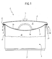
- the number 1 indicates in its entirety a kitchen utensil for cooking foods according to the present invention.
- the subject kitchen utensil conventionally comprises a containment body 2 presenting a bottom wall 3, for instance circular, oval or polygonal, and a side wall 4 emerging from the perimeter of the bottom wall.
- a containment body 2 presenting a bottom wall 3, for instance circular, oval or polygonal, and a side wall 4 emerging from the perimeter of the bottom wall.
- a lid 6 presenting, in central position and in correspondence with its outer surface, a grip element or knob 7.
- the kitchen utensil also comprises a laminar body 9 operatively interposed between the upper edge 5 of the side wall 4 of the containment body 2 and the lid 6 to define at least a first chamber 10, developing between the lower surface 9a of the laminar body itself and the containment body 2, and at least a second chamber 11, developing between the upper surface 9b of the laminar body 9 and the closure lid 6.
- the first chamber 10 is delimited at the bottom by the bottom wall 3, radially by the side wall 4 and at the top by the laminar body 9.
- the second chamber 11 is delimited at the bottom by the laminar body 9 and at the top by the closure lid 6.
- the laminar body 9 advantageously presents at least a first series of through holes 12 (see Figure 4) set to place in fluid communication the first chamber with the second chamber.
- the through holes 12 of the first series extend vertically and allow heat, steam, droplets of oil or of other substances, able to vapourise or to atomise at high temperature, to move from the first to the second chamber.
- the laminar body 9 is shaped according to the bottom wall of the utensil and thus it may present a circular, elliptical or polygonal conformation according to requirements.
- Such laminar body is defined by a thin sheet, suitably shaped and holed and obtained for instance by pressing metallic materials such as steel, aluminium and the like. This obviously does not exclude that the laminar body could be obtained from other materials suitable to be used in contact with foods and to operate at high temperatures.
- the laminar body 9 is also fitted with a perimeter edge 13 destined to be set in correspondence with the upper edge 5 of the side wall.
- the perimeter edge 13 of the laminar body defines at its top an annular seat wherein the corresponding perimeter portion 8 of the closure lid is to be housed. More precisely the edge 13 of the laminar body comprises a continuous folded lip extending along the whole upper edge 5 of the containment body 2.
- Such laminar body is also fitted with means 14 for removable coupling associated to the perimeter edge 13 to allow to position the laminar body itself selectively in an engaged condition, wherein the perimeter edge 13 of the laminar body 9 is fastened to the upper edge 5 of the containment body 2, so that the containment body and the laminar body are integral, and a disengaged condition, wherein the perimeter edge 13 of the laminar body 9 is unfastened from the upper edge 5 of the containment body 2 so that the laminar body can be removed from the containment body itself to perform the various functions which, as shall be better explained hereafter, the laminar body can carry out.
- the coupling means 14 comprise at least a first and a second tongue 15, 16, having each a first portion 15a, 16a fastened to the perimeter edge 13 of the laminar body 9 and a second portion 15b, 16b folded downward with respect to said first portion 15a, 16a to define a seat 17 wherein to house the upper edge 5 of the containment body 2.
- At least one of said first or second tongue 15, 16 is made of elastic material able to deform as a result of the coupling of the laminar body 9 with the upper edge 5 of the containment body 2.
- the first tongue 15 preferably presents the second portion 15b directed radially towards the interior of the containment body and a third portion 15c, consecutive to the second portion, folded in radially outward direction with respect thereto to define a snap coupling of the laminar body 9 with the upper edge 5 of the containment body.
- the second and the third portion 15b and 15c of the first tongue 15 must be made of elastic material to define said snap coupling.
- each tongue may be suitably dimensioned according to the various operational requirements encountered.
- the laminar body is fitted with grip means 21 operating in a radially external position with respect to said first and to said second chamber 10 and 11. More precisely, the grip means 21 radially protrude from the second chamber 11 also with the lid 6 in its engaged position and are preferably defined by a knob 22 terminally fastened to the third portion 15c of the first tongue.
- the grip means can comprise two of said knobs 22 emerging in radial direction externally with respect to said chambers and fastened to the laminar body 9.
- the grip knobs can preferably be set in diametrically opposite positions to enable easily to handle the laminar body.
- the laminar comprises also a second series of through holes 18 also set to place in fluid communication the first chamber with the second chamber 11.
- the holes 12 of the first series present a passage area noticeably greater than the passage area of the holes 18 of the second series.
- the holes 12 of the first series are positioned preferably at equal intervals from each other in correspondence with a central area 19 of the laminar body 9.
- the holes 18 of the second series are distributed along a perimeter band 20 of pre-set angular extension defined between the central area 19 and the perimeter edge 13 of the laminar body 9.
- the holes 18 of the second series are in much greater number, for instance several tens of holes, whereas the holes 12 of the first series are in very limited number, for instance 4-10 holes.
- the laminar body 9 is of concave shape with its concavity facing the closure lid 6, obviously with reference to the condition of engagement of the laminar body to the containment body, i.e. in operative conditions (see Figure 1).
- the volume of the second chamber 11 is maximised.
- the laminar body presents its concavity shaped and dimensioned in such a way as to define, with lid 6, a second chamber of suitable volume and, more precisely, of a volume that is greater than or equal to the ideal volume which the second chamber would present if the laminar body had a plane conformation.
- the concavity of the laminar body must not be too accentuated in order to be sufficiently distanced from the bottom without requiring the use of containment bodies 2 having a high side wall 4, thus also allowing for steam cooking or frying without immersion of the food housed in the second chamber.
- Laminar body 9 can also be provided with an auxiliary grip element 23 fastened to the upper surface 9b of the laminar body itself and comprising for instance a handle or a knob or yet another element which, under operative conditions, is entirely housed in the second chamber 11.
- auxiliary grip element 23 fastened to the upper surface 9b of the laminar body itself and comprising for instance a handle or a knob or yet another element which, under operative conditions, is entirely housed in the second chamber 11.
- This type of cooking can be performed with the maximum efficiency in terms of heat exploitation by positioning the lid 6 over the laminar body 9, in order to define the second chamber 11, essentially insulating the products placed on the laminar body 9 from the outside environment.
- heat and steam, passing through the holes 12, 18 obtained in the laminar body can perform an effective heating action on the products undergoing cooking.
- the subject kitchen utensil is also extremely versatile since it can be advantageously used for cooking foods such as pasta and the like which can be housed and cooked within the first chamber 10 and then, when completely cooked, be subjected to an effective action of removal and drainage of the water which can be made to flow out from the second series of holes 18 simply by tilting the utensil with the laminar body in the engaged condition.
- the invention attains important advantages.
- the kitchen utensil according to the present invention is extremely effective in cooking foods minimising heat dispersion and allowing to cook foods in a healthy manner without thereby reducing their organoleptic properties.
- the second chamber is essentially closed by the lid which allows only minimal steam and heat evacuations in correspondence with the perimeter edge of the containment body.
- the laminar element has a concave shape in order to maximise the volume of the second chamber.
- grip means positioned laterally and externally to the second chamber allows easily to handle the laminar body both by itself and in its engaged condition with the lid.
- the auxiliary grip means which can constitute an additional element to handle the laminar body or anyway a convenient engagement area for attaching the laminar body to a wall without thereby precluding the possibility of housing in any case the laminar body itself between lid and containment body in order to minimise the space required for stowing the entire kitchen utensil in appropriate cabinets.
Landscapes
- Engineering & Computer Science (AREA)
- Food Science & Technology (AREA)
- Cookers (AREA)
Claims (8)
- Küchengerät zum Kochen von Nahrungsmitteln, umfassend:ein Aufnahmegehäuse (2), das eine Bodenwand (3) und eine vom Umfang der Bodenwand emporsteigende Seitenwand (4) aufweist;einen Deckel (6), der beim Schließen einem oberen Rand (5) der Seitenwand (4) zuzuordnen ist,einen lamellenförmigen Körper (9), der wirksam zwischen dem oberen Rand (5) des Aufnahmegehäuses (2) und dem Deckel (6) liegt, um mindestens eine erste Kammer (10), die sich zwischen einer unteren Fläche (9a) des lamellenförmigen Körpers (9) selbst und dem Aufnahmegehäuse (2) abwickelt, und mindestens eine zweite Kammer (11) festzulegen, die sich zwischen einer oberen Fläche (9b) des lamellenförmigen Körpers (9) und des Deckels (6) abwickelt, wobei der lamellenförmige Körper (9) mindestens eine erste Reihe von durchgehenden Löchern (12) aufweist, die die erste Kammer (10) mit der zweiten Kammer (11) in Fließverbindung bringt,
dadurch gekennzeichnet, daß der lamellenförmige Körper (9) eine zweite Reihe von durchgehenden Löchern (18) umfaßt, die auch sie die erste Kammer (10) mit der zweiten Kammer (11) in Fließverbindung setzt, wobei die Löcher (12) der ersten Reihe eine Durchgangsfläche aufweist, die größer ist als jene der Löcher (18) der zweiten Reihe, wobei die Löcher (12) der ersten Reihe im Bereich einer mittigen Fläche (19) des lamellenförmigen Körpers (9) angeordnet sind, wobei die Löcher (18) der zweiten Reihe längs eines umlaufenden Streifens (20) vorgegebener Winkelausdehnung verteilt sind, die zwischen dem mittigen Bereich (19) und dem umlaufenden Rand (13) des lamellenförmigen Körpers (9) festgelegt ist. - Küchengerät nach Anspruch 1, dadurch gekennzeichnet, daß der lamellenförmige Körper (9) einen umlaufenden Rand (13) umfaßt, der dazu bestimmt ist, im Bereich des oberen Randes (5) der Seitenwand (4) angeordnet zu werden, und abnehmbare Koppelmittel (14) aufweist, die dem umlaufenden Rand zugeordnet sind, um die Positionierung des lamellenförmigen Körpers (9) wahlweise in einer Eingriffsstellung, in der der umlaufende Rand (13) des lamellenförmigen Körpers (9) an den oberen Rand (5) des Aufnahmegehäuses (2) gebunden ist, und in einer Freigabestellung zu erlauben, in der der umlaufende Rand (13) des lamellenförmigen Körpers (9) vom oberen Rand (5) des Aufnahmekörpers (2) befreit ist.
- Küchengerät nach Anspruch 2, dadurch gekennzeichnet, daß die Koppelmittel (14) mindestens eine erste und eine zweite Lasche (15, 16) umfassen, die jeweils einen ersten am umlaufenden Rand (13) des lamellenförmigen Körpers (9) befestigten Abschnitt (15a, 16a) und einen zweiten Abschnitt (15b, 16b) aufweisen, der unten gegenüber dem ersten Abschnitt umgebogen ist, um eine Aufnahme (17) festzulegen, wo der obere Rand (5) des Aufnahmegehäuses (2) aufgenommen wird.
- Küchengerät nach Anspruch 3, dadurch gekennzeichnet, daß mindestens eine der ersten oder der zweiten Laschen (15, 16) aus einem Federmaterial besteht.
- Küchengerät nach Anspruch 3, dadurch gekennzeichnet, daß mindestens die erste Lasche (15) einen zweiten Abschnitt (15b), der in Richtung des Aufnahmegehäuses (2) umgebogen ist, und einen dritten Abschnitt (15c) aufweist, der an den zweiten Abschnitt anschließt, und gegenüber diesem letzteren in radial äußeren Richtung umgebogen ist, um eine Schnappverbindung des lamellenförmigen Körpers (9) mit dem oberen Rand (5) des Aufnahmegehäuses (2) festzulegen.
- Küchengerät nach Anspruch 1, dadurch gekennzeichnet, daß der lamellenförmige Körper (9) konkaver Ausbildung ist, mit in Richtung des Deckels (6) gerichteten Konkavität.
- Küchengerät nach Anspruch 1, dadurch gekennzeichnet, daß es Greifmittel (21) umfaßt, die am lamellenförmigen Körper (9) angreifen und in einer gegenüber der ersten und der zweiten Kammer (10, 11) radial äußeren Stellung wirken.
- Küchengerät nach Anspruch 6, dadurch gekennzeichnet, daß es ein Hilfsgreifelement (23) umfaßt, das an der oberen Fläche (9b) des lamellenförmigen Körpers (9) befestigt ist, wobei das Hilfsgreifelement in dieser zweiten Kammer (11) vollständig aufgenommen ist.
Priority Applications (1)
| Application Number | Priority Date | Filing Date | Title |
|---|---|---|---|
| EP19970830539 EP0906739B1 (de) | 1997-10-23 | 1997-10-23 | Küchengerät zum Garen von Speisen |
Applications Claiming Priority (1)
| Application Number | Priority Date | Filing Date | Title |
|---|---|---|---|
| EP19970830539 EP0906739B1 (de) | 1997-10-23 | 1997-10-23 | Küchengerät zum Garen von Speisen |
Publications (2)
| Publication Number | Publication Date |
|---|---|
| EP0906739A1 EP0906739A1 (de) | 1999-04-07 |
| EP0906739B1 true EP0906739B1 (de) | 1999-04-14 |
Family
ID=8230821
Family Applications (1)
| Application Number | Title | Priority Date | Filing Date |
|---|---|---|---|
| EP19970830539 Expired - Lifetime EP0906739B1 (de) | 1997-10-23 | 1997-10-23 | Küchengerät zum Garen von Speisen |
Country Status (1)
| Country | Link |
|---|---|
| EP (1) | EP0906739B1 (de) |
Cited By (2)
| Publication number | Priority date | Publication date | Assignee | Title |
|---|---|---|---|---|
| WO2001058330A1 (de) | 2000-02-09 | 2001-08-16 | Fissler Gmbh | Aufsatz für pfannen und töpfe |
| KR20150123116A (ko) * | 2014-04-24 | 2015-11-03 | 채수연 | 조리용기용 덮개 |
Families Citing this family (3)
| Publication number | Priority date | Publication date | Assignee | Title |
|---|---|---|---|---|
| DE19962189A1 (de) * | 1999-12-22 | 2001-09-06 | Wmf Wuerttemberg Metallwaren | Kochgefäß |
| US20040200841A1 (en) * | 2003-04-09 | 2004-10-14 | Calphalon Corporation | Cookware lid |
| CN110123148B (zh) * | 2019-05-14 | 2020-07-14 | 北方工业大学 | 一种防蒸汽冷凝滴落的锅盖的制备方法和系统 |
Family Cites Families (8)
| Publication number | Priority date | Publication date | Assignee | Title |
|---|---|---|---|---|
| DE359687C (de) * | 1922-09-25 | Gerhard Schreiber | Kochtopf | |
| FR585697A (fr) * | 1924-09-15 | 1925-03-05 | Casserole à usages multiples | |
| US1664564A (en) * | 1927-04-21 | 1928-04-03 | Lipner Abe | Culinary strainer |
| CH207062A (de) * | 1939-01-19 | 1939-09-30 | Zug Metallwarenfab | Reis- und Gemüsekocher. |
| US2907467A (en) * | 1958-04-29 | 1959-10-06 | Jr Fred Machate | Cover |
| US3808963A (en) * | 1972-09-21 | 1974-05-07 | O Ludena | Steam cooker |
| DE3422011A1 (de) * | 1984-06-14 | 1985-12-19 | Fissler Gmbh, 6580 Idar-Oberstein | Kochtopf |
| EP0326105A1 (de) * | 1988-01-25 | 1989-08-02 | Henning Morgan Henderson | Dampfkochgerät |
-
1997
- 1997-10-23 EP EP19970830539 patent/EP0906739B1/de not_active Expired - Lifetime
Cited By (2)
| Publication number | Priority date | Publication date | Assignee | Title |
|---|---|---|---|---|
| WO2001058330A1 (de) | 2000-02-09 | 2001-08-16 | Fissler Gmbh | Aufsatz für pfannen und töpfe |
| KR20150123116A (ko) * | 2014-04-24 | 2015-11-03 | 채수연 | 조리용기용 덮개 |
Also Published As
| Publication number | Publication date |
|---|---|
| EP0906739A1 (de) | 1999-04-07 |
Similar Documents
| Publication | Publication Date | Title |
|---|---|---|
| US4000830A (en) | Lid for a cooking utensil | |
| US5653881A (en) | Straining vessel | |
| US4574776A (en) | Cooking utensil | |
| US4310418A (en) | Cookware with drainage lid | |
| US20240251987A1 (en) | Cookware Assembly | |
| US4331127A (en) | Double boiler and steam cooker | |
| CA2109044C (en) | Microwave cooker | |
| US6196120B1 (en) | Steamer insert, steamer assembly and method | |
| US6401602B1 (en) | Multi-purpose cooking pan | |
| US12035836B2 (en) | Cookware assembly | |
| KR19980024205A (ko) | 식품의 생태학적 조리 시스템 | |
| US4686958A (en) | Versatile outdoor cooker | |
| AU2001245013A1 (en) | The multifunctional combined apparatus for food preparation | |
| US4467784A (en) | Boil-over preventer | |
| US20060243141A1 (en) | Food Container, Strainer, Cooker, and Strained Liquid Collector | |
| JP2018525183A (ja) | 調理はね防止デバイス及び方法 | |
| EP0906739B1 (de) | Küchengerät zum Garen von Speisen | |
| US10368678B2 (en) | Cooking vessel with or without retainable cover and method of making the same | |
| KR20110037387A (ko) | 조리용기의 뚜껑 및 구이판과 전골냄비의 겸용이 가능한 조리기기 | |
| JPH09108114A (ja) | 茹で物の水切り具 | |
| SU1687250A1 (ru) | Посуда дл приготовлени пищи | |
| SU1738251A1 (ru) | Кастрюл | |
| US20250089937A1 (en) | Baking Tray Assembly | |
| KR200278443Y1 (ko) | 조리기구 | |
| KR100903036B1 (ko) | 조리용기의 넘침방지구조 |
Legal Events
| Date | Code | Title | Description |
|---|---|---|---|
| GRAG | Despatch of communication of intention to grant |
Free format text: ORIGINAL CODE: EPIDOS AGRA |
|
| GRAG | Despatch of communication of intention to grant |
Free format text: ORIGINAL CODE: EPIDOS AGRA |
|
| GRAH | Despatch of communication of intention to grant a patent |
Free format text: ORIGINAL CODE: EPIDOS IGRA |
|
| GRAH | Despatch of communication of intention to grant a patent |
Free format text: ORIGINAL CODE: EPIDOS IGRA |
|
| PUAI | Public reference made under article 153(3) epc to a published international application that has entered the european phase |
Free format text: ORIGINAL CODE: 0009012 |
|
| GRAA | (expected) grant |
Free format text: ORIGINAL CODE: 0009210 |
|
| 17P | Request for examination filed |
Effective date: 19980520 |
|
| AK | Designated contracting states |
Kind code of ref document: A1 Designated state(s): ES IT |
|
| AK | Designated contracting states |
Kind code of ref document: B1 Designated state(s): ES IT |
|
| PG25 | Lapsed in a contracting state [announced via postgrant information from national office to epo] |
Ref country code: ES Free format text: THE PATENT HAS BEEN ANNULLED BY A DECISION OF A NATIONAL AUTHORITY Effective date: 19990414 |
|
| AKX | Designation fees paid |
Free format text: ES IT |
|
| PLBE | No opposition filed within time limit |
Free format text: ORIGINAL CODE: 0009261 |
|
| STAA | Information on the status of an ep patent application or granted ep patent |
Free format text: STATUS: NO OPPOSITION FILED WITHIN TIME LIMIT |
|
| 26N | No opposition filed | ||
| PG25 | Lapsed in a contracting state [announced via postgrant information from national office to epo] |
Ref country code: IT Free format text: LAPSE BECAUSE OF NON-PAYMENT OF DUE FEES Effective date: 20051023 |