EP0906720B1 - Appareil et méthode pour la reconnaissance sans contact des limites de la zone de travail ou de sa taille correspondante - Google Patents
Appareil et méthode pour la reconnaissance sans contact des limites de la zone de travail ou de sa taille correspondante Download PDFInfo
- Publication number
- EP0906720B1 EP0906720B1 EP98115144A EP98115144A EP0906720B1 EP 0906720 B1 EP0906720 B1 EP 0906720B1 EP 98115144 A EP98115144 A EP 98115144A EP 98115144 A EP98115144 A EP 98115144A EP 0906720 B1 EP0906720 B1 EP 0906720B1
- Authority
- EP
- European Patent Office
- Prior art keywords
- working
- parameter
- limit
- measurement
- working limit
- Prior art date
- Legal status (The legal status is an assumption and is not a legal conclusion. Google has not performed a legal analysis and makes no representation as to the accuracy of the status listed.)
- Expired - Lifetime
Links
- 238000000034 method Methods 0.000 title claims description 40
- 238000005259 measurement Methods 0.000 claims description 40
- 238000011156 evaluation Methods 0.000 claims description 30
- 238000004364 calculation method Methods 0.000 claims description 6
- 238000012937 correction Methods 0.000 claims description 5
- 230000010363 phase shift Effects 0.000 claims description 3
- 230000001105 regulatory effect Effects 0.000 claims description 3
- 238000012545 processing Methods 0.000 description 74
- 238000003754 machining Methods 0.000 description 24
- 230000008859 change Effects 0.000 description 11
- 238000005520 cutting process Methods 0.000 description 10
- 238000010586 diagram Methods 0.000 description 10
- 239000003550 marker Substances 0.000 description 9
- 238000001514 detection method Methods 0.000 description 8
- 230000005540 biological transmission Effects 0.000 description 7
- 238000003306 harvesting Methods 0.000 description 7
- 230000008569 process Effects 0.000 description 6
- 238000003860 storage Methods 0.000 description 4
- 238000004891 communication Methods 0.000 description 3
- 230000001419 dependent effect Effects 0.000 description 3
- 230000005484 gravity Effects 0.000 description 3
- 230000003287 optical effect Effects 0.000 description 3
- 239000002689 soil Substances 0.000 description 3
- 230000008901 benefit Effects 0.000 description 2
- 238000002592 echocardiography Methods 0.000 description 2
- 238000012854 evaluation process Methods 0.000 description 2
- 230000002441 reversible effect Effects 0.000 description 2
- 238000012935 Averaging Methods 0.000 description 1
- 244000025254 Cannabis sativa Species 0.000 description 1
- 230000004913 activation Effects 0.000 description 1
- 230000009286 beneficial effect Effects 0.000 description 1
- 230000007423 decrease Effects 0.000 description 1
- 238000013461 design Methods 0.000 description 1
- 238000011161 development Methods 0.000 description 1
- 238000009826 distribution Methods 0.000 description 1
- 238000003708 edge detection Methods 0.000 description 1
- 230000000694 effects Effects 0.000 description 1
- 230000010354 integration Effects 0.000 description 1
- 238000010606 normalization Methods 0.000 description 1
- 230000005855 radiation Effects 0.000 description 1
- 230000009467 reduction Effects 0.000 description 1
- 238000010187 selection method Methods 0.000 description 1
- 238000004904 shortening Methods 0.000 description 1
- 238000003971 tillage Methods 0.000 description 1
- 238000002604 ultrasonography Methods 0.000 description 1
Images
Classifications
-
- A—HUMAN NECESSITIES
- A01—AGRICULTURE; FORESTRY; ANIMAL HUSBANDRY; HUNTING; TRAPPING; FISHING
- A01B—SOIL WORKING IN AGRICULTURE OR FORESTRY; PARTS, DETAILS, OR ACCESSORIES OF AGRICULTURAL MACHINES OR IMPLEMENTS, IN GENERAL
- A01B69/00—Steering of agricultural machines or implements; Guiding agricultural machines or implements on a desired track
- A01B69/007—Steering or guiding of agricultural vehicles, e.g. steering of the tractor to keep the plough in the furrow
- A01B69/008—Steering or guiding of agricultural vehicles, e.g. steering of the tractor to keep the plough in the furrow automatic
-
- A—HUMAN NECESSITIES
- A01—AGRICULTURE; FORESTRY; ANIMAL HUSBANDRY; HUNTING; TRAPPING; FISHING
- A01B—SOIL WORKING IN AGRICULTURE OR FORESTRY; PARTS, DETAILS, OR ACCESSORIES OF AGRICULTURAL MACHINES OR IMPLEMENTS, IN GENERAL
- A01B69/00—Steering of agricultural machines or implements; Guiding agricultural machines or implements on a desired track
- A01B69/001—Steering by means of optical assistance, e.g. television cameras
-
- A—HUMAN NECESSITIES
- A01—AGRICULTURE; FORESTRY; ANIMAL HUSBANDRY; HUNTING; TRAPPING; FISHING
- A01D—HARVESTING; MOWING
- A01D41/00—Combines, i.e. harvesters or mowers combined with threshing devices
- A01D41/12—Details of combines
- A01D41/127—Control or measuring arrangements specially adapted for combines
- A01D41/1278—Control or measuring arrangements specially adapted for combines for automatic steering
Definitions
- Such a device is from the German Patent application 24 55 836 known.
- These disclosed device includes a transmission and Receiver unit seen in the direction of travel in front and to the stock in one point, something at the same time angle downwards towards the floor without contact locates a crop edge. The reflection becomes then a steering signal according to various evaluation methods generated.
- the transmitter unit works with narrowband Light emitters, polarizers and Modulators, short-wave, highly focused electromagnetic Waves or sound waves.
- the reflected Signals are compared to a setpoint evaluated and an automatic steering device fed in such a way that the lateral distance between the cutting edge and Edge of the crop is minimized.
- the Setup periodically around an approximately vertical axis panned and from the middle manager of the received signals the location of the edge relative to one Setpoint generated.
- Disadvantages of this device are the attachment of the device to the machine and the evaluation of the sensor signals.
- the disclosed device arrangement is only suitable to a limited extent for the detection of an existing edge.
- the scanning beam is reflected laterally from the existing edge and the distance to the edge is determined from the received signal.
- Fine adjustment and exact adherence to the scanning location on the edge are therefore required. This can only be achieved with high expenses. Therefore variable variables known per se such as stock height, working height, changes in machine and terrain inclination, together or individually, have a strong influence on the received signal.
- Another German patent 195 08 942 discloses a self-steering device in which a locating device is arranged at a distance above the grain in such a way that the locating signals locate the processing edge obliquely from above, approximately perpendicular to the cutting device knife.
- Various location signals and signal evaluations are disclosed, the unprocessed and processed field piece being detected by a location device. This is done using an ultrasonic beam or a laser scanner. In a particularly simple embodiment, two-point control is implemented by two laser partial location beams.
- the serious disadvantage of these locating devices is the evaluation of the received signals.
- a laser scanner can only be used to detect an edge or track that can be recognized in the height profile. The system fails at frequently occurring grain stores. Means must also be used which make it possible to maintain an approximately constant scanning distance in order to prevent the maximum working distance of the laser beam from being exceeded.
- the evaluation methods described are dependent on the quality of the reference quantity.
- the echoes must be based on a reference variable can be assessed. But it did shown that precisely this reference variable is not a constant and can be varied along an edge would.
- the locating device therefore only delivers piece by piece and with high correction effort for the detection an edge satisfactory results. For the Use of the device on other types. machining limits there is no suitability.
- German patent specification 195 08 941 a further locating device is disclosed, in which three partial locating devices are arranged on an agricultural machine, of which a first is aimed at the harvested field, a second at the not harvested field and a third at the crop edge.
- the reference variable for the third partial locating device is derived from the mean value of the locating signals of the first and second partial locating devices. It also has a disadvantage here that the echo of the partial location signals varies greatly and thus no satisfactory edge tracking is made possible.
- the stock density, scanning distance and stock or stubble height affect the partial location echoes. A necessary integration and averaging over several measurements makes it impossible to react to rapid changes in the echo, which can even occur in opposite directions, in such a way that reliable edge detection and tracking is possible.
- the triple execution of the locating device is also very cost-intensive and requires a special synchronization of the transmission signals.
- This device is unsuitable for the location of crop swaths.
- the reference values determined by the outer partial location devices do not represent the required reference values.
- the middle partial location device must be aligned over a swath so that the center of the lobe lies on the center of the swath. This alignment is possible, but no edge signal can be generated by the device in the middle of the swath.
- a change in the echo of the middle partial locating device only takes place after leaving the locating lobe from the crop swath.
- a partial locating device would have to determine a reference variable from the furrow sole. However, this is not possible due to the width of the ultrasonic beam.
- the device is not suitable for recognizing different edges and processing limits. In many cases, the color difference between the processed and unprocessed field is very small. Furthermore, the accuracy of the device is determined by the number and size of the receiving elements and, with a sufficient resolution, results in high costs.
- Another device has become known from German Patent 197 26 917.
- a scanning device for detecting contours extending over the floor is disclosed.
- a laser scanner attached to a harvesting machine scans the contour in front of a harvesting machine by measuring the distance.
- Distance jump points are determined from the contours and assigned to a scan angle.
- a steering difference is determined in conjunction with the associated scan angle and fed to automatic steering.
- the value with the smallest distance is selected as the guide variable from the measured values.
- this device is only suitable for the detection of processing limits that have a change in the height profile. This device fails at processing limits that do not have these changes, such as, for example, at storage locations in the grain stock or at tillage limits.
- a reduction of the receiving devices to one device is achieved by a scanning device.
- a transmission beam is pivoted about an approximately vertical axis over a swivel angle of up to 180 °.
- An advantageous attachment of the device is chosen so that the transmission beam runs in the center of the swivel range on an axis lying parallel to the longitudinal axis of the vehicle.
- the receiving device is then controlled synchronously with the transmitted beam or adapted to the received beam by suitable means, for example by active swivel optics or via optical lenses.
- suitable means for example by active swivel optics or via optical lenses.
- An advantageous embodiment of the invention can therefore be seen in a pivoting range reduced to a few degrees, for example +/- 6 ° around the center of the pivoting range. Another advantage results from the fact that a higher scan rate can be used, which improves the resolution of successive contours.
- the areas of application of the device are various implements or harvesting machines with different processing sequences. It is therefore intended to equip the device with various calculation methods for generating processing edges or guide variables.
- the operator of the device selects the desired device application via a manual input interface, for example via a keyboard, a rotary switch or a button.
- the required calculation method is then selected accordingly in the device.
- the operator of the device can use known means to inform that the calculation method should be automatically reselected.
- the selection of the calculation method is selected cyclically or controlled by a variable dependent on the machining process. For example, it is conceivable to activate a selection process by lowering the cutting unit or by switching on a PTO.
- the device supplies the relative machining limit or guide position to the device attachment location on the machine.
- the device is attached to an agricultural working or harvesting machine in such a way that the transmission beam detects the guideline or processing limit ahead of the implement.
- An advantageous attachment is achieved by aligning the middle of the measuring range parallel to the direction of travel.
- the device work area center is usually selected as the target size. The best location is therefore to mount the device directly vertically above the machining limit or guide size. As a result, there is a jump in the distance or a jump in the processing-specific. Size best recognized in the area of the target direction. Furthermore, deviations from the target direction on both sides can be recognized to the same extent.
- the traction and working devices are known to be positioned somewhat across the slope to compensate for the downhill forces.
- the work machine rotates around its center of gravity without changing the direction of travel. All machine parts spaced from the center of gravity change their position relative to the direction of travel.
- the device attachment is typically spaced from the center of gravity. The distance from the center of the measuring range is no longer parallel to the direction of travel.
- a control difference is determined by the device. Correction of the setpoint or actual value by means of an offset entered manually compensates for this control difference. Control differences that are caused by a relative change in the mounting position can also be eliminated by a further embodiment of the invention. So it is provided to change the mounting position and / or inclination manually or automatically.
- the position or inclination of the device attachment can be changed by known means such as, for example, a servomotor, so that the control differences are compensated for. Furthermore, it will be necessary to change the attachment of the device directly to work equipment with different working heights or depths. So that the foresight of the device is maintained or at least prevented that the scanning beam leaves the processing field in the working position, it may be necessary to correct the mounting height or the inclination of the device. This can be done automatically by a control according to a working height or depth measurement or by manual setting. A change in the horizontal position makes sense when the device is used in connection with a soil cultivation device if a changed overlap with the previous cultivation track is desired. For this purpose, the device is moved closer to the center of the tractor, for example with an actuator. The setpoint size is thereby shifted and the automatic steering causes the machine with a changed relative setpoint size to be guided along to the processing limit or control size.
- a further embodiment of the invention is achieved by including the device in a field end or start program.
- the beginning or the end of a processing limit or guide variable is derived from the determined processing limit curves or guide variables and is transmitted automatically using known communication means.
- An automatic field start is activated when the device detects a processing limit or guide variable. The driver is informed of this and the automatic starts after a time or distance has elapsed. For example, the implement is lowered and the PTO is switched on.
- the individual measured variables with a relative or absolute position in existing ones Store storage media.
- the today existing, high-precision GPS location systems allow the respective reflectance measurements in conjunction with a crop position correction and a absolute position (X, Y, possibly Z coordinates) save.
- a relative Size such as the scan angle or in the case of an array receiver arrangement, the Receiver number or position to be saved.
- Communication of the device with others Evaluation electronics, the automatic steering controller or the field end or beginning can be over known means of communication such as via a known CAN bus connection.
- An emitted electromagnetic wave is reflected from a contour point and from the device receive. From the received signals the distance and at least one processing limit specific Size determined and saved. The measured values become from the individual measured variables selected over a fixture working width and a contour is calculated from this. These individual contours can be cached again as needed become. Using a selected evaluation process the individual contours or series of measurements examined and the location of the machining limit or Guide variable generated. From the comparison of the target position with the determined actual position becomes a control difference determined and a manipulated variable for a downstream, automatic steering derived. The method certainly determines a processing limit or guide variable and allows a work machine safely along a machining limit or Guide variable can be performed.
- no absolute reference variable is used in the evaluation of the measured variable, but at least one measured variable is selected as the reference variable and used for the evaluation.
- the smallest distance value is assumed to be one and the largest distance value to be zero.
- This standardization normalizes all height contour changes to a jump range from 0-1. The actual jump in height no longer matters and the subsequent evaluation does not require any further adjustment. Changes in distance due to a pitching movement or a ride up or down the working machine are eliminated by the standardization.
- Another standardization can be used, for example, for the standardization of the processing-specific size.
- the measured values of a measured variable are normalized to a reference variable at a specific scan angle.
- a normalization of the measured values over a device working width to the leftmost measured value is mentioned. If a piece of grain was harvested clockwise, this would mean that all measured values would be standardized to a measured value that originates from the reflection of an electromagnetic wave at a stubble field. With these methods, fluctuations in, for example, a processing limit-specific variable along a processing limit or guide variable are eliminated. If there are strong unreal fluctuations in the reference variable, it is provided that a plausibility check is carried out and if necessary a reference variable is averaged, rejected and exchanged for a previous one.
- the areas of application of the device are various processing limits or guide variables.
- the device must therefore include various evaluation methods. As already mentioned, these methods can be selected manually or automatically.
- the measured values are examined according to a specific measured value assignment. A selection procedure is described below as an example. First, only measured values of a measured variable are searched over a device working width for the largest or smallest measured value and its relative position and locations are saved. Furthermore, the measured variables of a device working width after the largest measured value jump and their associated relative position are examined. In a further embodiment of the method, it is only possible to search for jump points with certain signs.
- the selection process in the distance measurement finds a maximum or minimum value in only one area, it is a processing limit or guide variable with a deepening or increasing in the contour. It can then be assumed that it is a furrow, track marker track or a swath. If only a range with minimum values can be determined over a device working width, the recognized processing limit or guide variable is a guide variable spaced from the ground, such as a swath.
- the recognized processing limit or guide variable is a floor cut such as a track marker track or furrow.
- the position of the largest measured value is compared with the position of the largest measured value jump, with a possible sign selection. If these lie close together, it is a furrow. If no area within a device working width with minimum or maximum values but a jump in distance can be determined from the measured values of a measured variable, then it is a processing edge.
- the evaluation of the processing limit-specific size provides a further selection aid.
- the processing limit-specific sizes are examined for minimum or maximum values and jump points with possible sign selection within a device working width. If corresponding positions are found here, these are compared with the previous process selection criteria. If only a range with minimum or maximum values can be determined over a device working width, there is a changed top surface structure and / or a change in moisture at this point. This is, for example, a track marker track, a furrow or a swath at this point. If you then add the decision criteria from the distance measurement, a clear evaluation method selection can be carried out.
- the selection criteria used to select an evaluation method are also used to identify the actual position of the processing limit or guide variable.
- the actual position of the known processing limit or guide variable can then be derived from just one examination of a measured variable.
- the evaluation method for recognizing a processing edge an edge can already be determined from the jump point in the distance measurement. This result is confirmed here by the determination of a further jump point which is usually present in the processing limit-specific size. If no actual position can be determined from a measured variable, the other criterion used in the selection process is used.
- One embodiment of the method is to be seen in the fact that if several actual position are determined from several measured variable examinations, these are compared with one another and if necessary offset or a result is selected on the basis of plausibility examinations. In order to obtain an even higher level of security, it is also intended to compare previous actual positions with the current result and, if necessary, to correct this.
- the edge distribution is then advantageously determined from a plurality of stored device working width contours. They then also allow a prediction of the likely subsequent edge position.
- an end or the beginning of the processing limit or guide variable is generated from the measured values. If the evaluation method can no longer determine the actual position of the machining limit or the guide variable, the machine has reached the end of the machining field. By looking ahead at the device, the end of the field is recognized even before the implement is reached. Since work must continue until the end of the field is reached, the automatic steering is steered to the end of the field with a held steering signal. An automatic field end is then activated at the end of the processing strip via a timer or a route measurement or an activation setting command (for example a steering wheel rotation). In order to rule out possible wrong decisions in the field end detection, the driver is informed of a field end detection. He then has the option of deactivating the automatic system until the end of the field is reached.
- the automatic field end control automatically starts various machine processes. For example, the processing device is lifted and the PTO is switched off after a certain time.
- a Automatic field start activated.
- the operator of the This is communicated to the machine. Through the The device's foresight becomes the machining limit or guide variable before reaching the Machine recognized at the beginning of the field.
- the automatic Steering can then automatically immediately if necessary be switched on. Until then the work machine the field start automatic can make certain machine settings.
- the Machine operators also have the option in this Time to deactivate the automatic. For the right one Field start sequence, can be a path, time, or function dependent Control may be necessary.
- the intensity of the reflection decreases with increasing distance. There is an increase in register increasing moisture. The reflection intensity a freshly worked field piece or a freshly drawn track is therefore higher than that surrounding unprocessed field piece.
- the machining limit specific Size and distance proportional to each other becomes the device orientation controlled according to a procedure or regulated that the mounting position or Inclination of the device is changed so that at least one measured variable is approximately constant is held. This measure will at least strengthened a machining limit feature so that better detection of the machining limit or guide variable is guaranteed.
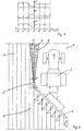
- the associated distance measurement result E of the device 5 is shown schematically. Due to the attachment position on the work machine, elevations in the profile P have the effect of shortening the distance.
- the representation of the intensity I in the diagram above in FIG. 1 is approximately inversely related to the distance measurement diagram E.
- the intensity I of the reflection of the laser beam is higher on the processed field piece 1 than on the unprocessed field piece 2. Only the point at which the largest jump occurs is of interest for evaluating the values. For this reason, the measured values of a device working width have been standardized to the smallest values as a reference variable and have been presented without a unit. All subsequent measurements can be compared and used to identify the guideline.
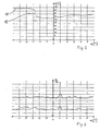
- FIG. 3 shows diagrams similar to FIG. 1.
- the profile P is shown by a mowing edge, based on a swivel angle range ⁇ of a device 5 according to the invention.
- Diagrams E and I above show the results of a measurement over an entire swivel angle range.
- the harvested field piece 2 is shown in the range from -6 ° to -1 °.
- the range -1 ° to + 6 ° represents a standing crop 1.
- the harvested field is identified by the distance measurement E by the larger distance values and the standing crop 2 by the shorter distance values. When evaluating the intensity, the relationships are exactly the opposite.
- the evaluation process determines the jump points and assigns them to a swivel angle and calculates the actual position of the machining limit to the current direction of travel. It can be derived from FIG. 3 that the current direction of travel of the harvesting machine and the course of the processing edge differ by 1 °. Consequently, a control variable must be generated from this control deviation, which enables the working machine 10.2 to be traced back to its required target course.
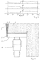
- FIG. 4 shows the top view of a harvesting machine 10 shown in work.
- the Cutting unit 11 is an inventive on the left side Device 5 attached.
- the electromagnetic Waves, here in the form of a laser beam 6, are in front of the cutting unit 11 in the direction of travel the processing limit 8 is pivoted.
- the location the device 5 is on the cutting unit 11 chosen so that the device working width center with a desired header utilization exactly lies on the processing limit.
- a measured variable (here the distance ) represented by individual measured values 12, in which the removal value E is assigned to a swivel angle ⁇ are.
- the distance By interpolating the measured values 12 you get a measurement curve over a swivel range 9 of the device 5.
- Deriving the distance according to the swivel angle then provides information about the relative Location of the largest jump in measured values or the processing limit to the direction of travel Harvester.
- the processing limit is here at the location of the measured value jump 13 at a Swivel angle of approx. -2.8 °.
Landscapes
- Life Sciences & Earth Sciences (AREA)
- Environmental Sciences (AREA)
- Engineering & Computer Science (AREA)
- Mechanical Engineering (AREA)
- Soil Sciences (AREA)
- Guiding Agricultural Machines (AREA)
- Control Of Position, Course, Altitude, Or Attitude Of Moving Bodies (AREA)
Claims (23)
- Dispositif pour la reconnaissance sans contact de limites de zone de travail ou de grandeurs de référence, notamment pour le guidage automatique de machines de travail (3, 10) agricoles le long d'une grandeur de référence qui a été produite au cours d'une étape de travail antérieure, identique ou différente, et est déterminante pour l'étape de travail à venir ou consécutive, le dispositif (5) étant disposé au-dessus de la limite de zone de travail (7; 8) et étant formé d'au moins un dispositif émetteur qui émet des ondes électromagnétiques d'une manière telle, que les limites de zone de travail (7; 8) ou les grandeurs de référence soient détectées à l'avance dans la direction de travail, et d'au moins un dispositif récepteur dans lequel sont prévus des moyens qui déterminent la distance par rapport aux différents points de réflexion des ondes, caractérisé en ce qu'il est prévu des moyens qui, à partir de la réflexion d'une onde électromagnétique émise, déterminent une première grandeur spécifique des limites de zone de travail ainsi qu'au moins une grandeur spécifique des limites de zone de travail supplémentaire.
- Dispositif selon la revendication 1, caractérisé en ce qu'à partir de la réflexion d'ondes, on détermine l'intensité en tant qu'une grandeur spécifique des limites de zone de travail.
- Dispositif selon la revendication 1 ou 2, caractérisé en ce qu'à partir de la réflexion d'ondes, on détermine le déphasage en tant qu'une grandeur spécifique des limites de zone de travail.
- Dispositif selon une ou plusieurs des revendications 1 à 3, caractérisé en ce qu'on utilise au moins un dispositif émetteur et un ou plusieurs dispositifs récepteurs disposés en réseau.
- Dispositif selon une ou plusieurs des revendications 1 à 4, caractérisé en ce que le dispositif émetteur, voire le dispositif récepteur, est un dispositif à balayage.
- Dispositif selon une ou plusieurs des revendications 1 à 5, caractérisé en ce que la largeur de travail du dispositif peut être adaptée en fonction de l'utilisation et peut ne représenter que quelques degrés d'angle de balayage, par exemple +/- 6° autour du centre de la zone de pivotement.
- Dispositif selon une ou plusieurs des revendications 1 à 6, caractérisé en ce que grâce à des moyens adaptés, le procédé de calcul pour la génération d'une limite de zone de travail ou d'une grandeur de référence et le procédé adapté à la limite de zone de travail ou à la grandeur de référence présente peuvent sélectionnés de manière automatique ou manuelle.
- Dispositif selon une ou plusieurs des revendications 1 à 7, caractérisé en ce qu'il est prévu des moyens qui permettent de transmettre la position/situation de la limite de zone de travail (7, 8) ou la grandeur de référence, de manière directe ou après correction, avec un décalage, une valeur de correction de site d'utilisation et/ou de largeur de travail, à une direction automatique de véhicule, par des moyens connus, par exemple via un système de bus de véhicule.
- Dispositif selon une ou plusieurs des revendications 1 à 8, caractérisé en ce que les unités d'émission et les unités de réception sont montées réglables manuellement ou de manière automatique dans la position horizontale et/ou verticale et/ou dans au moins une direction d'inclinaison.
- Dispositif selon une ou plusieurs des revendications 1 à 9, caractérisé en ce qu'il est prévu des moyens qui détectent la fin ou le début d'une limite de zone de travail (7, 8) ou d'une grandeur de référence, la signalent au conducteur et la transmettent par des moyens connus à un automatisme de fin ou de début de champ.
- Dispositif selon une ou plusieurs des revendications 1 à 10, caractérisé en ce qu'il est prévu des dispositifs qui permettent de mémoriser des valeurs de distance déterminées et les grandeurs associées spécifiques des limites de zone de travail en relation avec une position absolue, par exemple des coordonnées D-GPS, ou avec une position relative, par exemple l'angle de balayage par rapport à la machine de travail (3; 10).
- Procédé de détection d'une limite de zone de travail ou d'une grandeur de référence comportant les étapes suivantes:émission d'une onde électromagnétique,réception de l'onde électromagnétique réfléchie et exploitation en fonction d'une première grandeur spécifique de limite de zone de travail et d'au moins une grandeur spécifique de limite de zone de travail supplémentaire,mémorisation des différentes valeurs de mesure,calcul de contours individuels en fonction d'une largeur de travail de dispositif à partir des différentes valeurs de mesure,examen des valeurs de mesure pour une largeur de travail de dispositif par un procédé d'exploitation sélectionné,génération d'une position réelle de la limite de zone de travail ou de la grandeur de référence,détermination de la différence de réglage à partir de la comparaison position réelle/position de consigne et génération d'une grandeur de réglage pour le guidage automatique.
- Procédé selon la revendication 12, caractérisé en ce que les valeurs de mesure d'une largeur de travail de dispositif sont exploitées de manière normée sur au moins une valeur de mesure associée.
- Procédé selon une des revendications 12 ou 13, caractérisé en ce que pour reconnaítre une limite de zone de travail (7, 8) ou une grandeur de référence, un procédé d'exploitation est sélectionné de manière automatique.
- Procédé selon une ou plusieurs des revendications 12 à 14, caractérisé en ce qu'un procédé d'exploitation est sélectionné en fonction de la relation grandeur de mesure/ valeur de mesure maximale ou minimale/plus grande différence de niveau de valeur de mesure (13) et de sa position associée, en explorant les grandeurs de mesure sur une largeur de travail de dispositif à la recherche des points avec les valeurs de mesure (17) les plus élevées ou les valeurs de mesure (12) les plus faibles ou de la plus grande différence de niveau de valeur de mesure (13).
- Procédé selon une ou plusieurs des revendications 12 à 15, caractérisé en ce que la position réelle d'une limite de zone de travail ou d'une grandeur de référence est déduite par une combinaison de caractéristiques de grandeurs de mesure sur une ou sur plusieurs largeur(s) de travail de dispositif.
- Procédé selon une ou plusieurs des revendications 12 à 16, caractérisé en ce que pour reconnaítre de manière sûre un bord (8) de zone de travail ou une bifurcation (7), on recherche sur au moins une largeur de travail de dispositif la position de la plus grande différence de niveau d'une grandeur spécifique de limite de zone de travail et la position de la plus grande différence de niveau de la mesure de distance et en cas de coïncidence approchée on sélectionne celles-ci comme position réelle.
- Procédé selon une ou plusieurs des revendications 12 à 17, caractérisé en ce que lorsque pour une grandeur de mesure seule une différence de niveau peut être sélectionnée, celle-ci est sélectionnée comme position réelle.
- Procédé selon une ou plusieurs des revendications 12 à 18, caractérisé en ce qu'à partir des grandeurs de mesure on détermine la fin ou le début d'une limite de zone de travail (7, 8) d'une grandeur de référence.
- Procédé selon la revendication 19, caractérisé en ce que la fin détectée ou le début détecté est signalé au conducteur du véhicule, ou un automatisme de fin de champ ou de début de champ est activé.
- Procédé selon une ou plusieurs des revendications 12 à 20, caractérisé en ce que, lorsque pour une grandeur de mesure seule, une différence de niveau peut être sélectionnée, celle-ci est sélectionnée comme position réelle.
- Procédé selon une ou plusieurs des revendications 12 à 21, caractérisé en ce que le dispositif émetteur /les dispositifs récepteurs dans leur position de montage ou leur inclinaison sont réglés ou commandés de telle sorte qu'au moins une grandeur spécifique de limite de zone de travail déterminée soit constante.
- Procédé selon une ou plusieurs des revendications 12 à 22, caractérisé en ce que les valeurs de distance déterminées et la grandeur spécifique de limite de zone de travail correspondante sont associées à une position absolue, par exemple coordonnées D-GPS, ou à une position relative, par exemple angle de balayage par rapport à la machine de travail (3; 10) et mémorisées.
Applications Claiming Priority (2)
| Application Number | Priority Date | Filing Date | Title |
|---|---|---|---|
| DE19743884 | 1997-10-04 | ||
| DE19743884A DE19743884C2 (de) | 1997-10-04 | 1997-10-04 | Vorrichtung und Verfahren zur berührungslosen Erkennung von Bearbeitungsgrenzen oder entsprechenden Leitgrößen |
Publications (3)
| Publication Number | Publication Date |
|---|---|
| EP0906720A1 EP0906720A1 (fr) | 1999-04-07 |
| EP0906720B1 true EP0906720B1 (fr) | 2003-11-05 |
| EP0906720B2 EP0906720B2 (fr) | 2006-07-12 |
Family
ID=7844592
Family Applications (1)
| Application Number | Title | Priority Date | Filing Date |
|---|---|---|---|
| EP98115144A Expired - Lifetime EP0906720B2 (fr) | 1997-10-04 | 1998-08-12 | Appareil et méthode pour la reconnaissance sans contact des limites de la zone de travail ou de sa taille correspondante |
Country Status (6)
| Country | Link |
|---|---|
| US (1) | US6095254A (fr) |
| EP (1) | EP0906720B2 (fr) |
| BR (1) | BR9803986B1 (fr) |
| DE (2) | DE19743884C2 (fr) |
| RU (1) | RU2215389C2 (fr) |
| UA (1) | UA57730C2 (fr) |
Cited By (1)
| Publication number | Priority date | Publication date | Assignee | Title |
|---|---|---|---|---|
| EP4606198A1 (fr) * | 2024-02-21 | 2025-08-27 | Maschinenfabrik Bernard Krone GmbH & Co. KG | Train de travail avec un tracteur et un outil de travail |
Families Citing this family (49)
| Publication number | Priority date | Publication date | Assignee | Title |
|---|---|---|---|---|
| DE19726917A1 (de) * | 1997-06-25 | 1999-01-07 | Claas Selbstfahr Erntemasch | Vorrichtung an Landmaschinen zur berührungslosen Abtastung von sich über den Boden erstreckenden Konturen |
| SE9704398L (sv) * | 1997-11-28 | 1998-12-14 | Spectra Precision Ab | Anordning och förfarande för att bestämma läget för bearbetande del |
| DE19830858A1 (de) | 1998-07-10 | 2000-01-13 | Claas Selbstfahr Erntemasch | Vorrichtung und Verfahren zur Bestimmung einer virtuellen Position |
| DE19845666B4 (de) | 1998-10-05 | 2005-08-25 | Claas Selbstfahrende Erntemaschinen Gmbh | Lenkautomatik mit Ultraschall-Ortungsvorrichtung |
| US6115481A (en) | 1998-10-22 | 2000-09-05 | Centrak, Llc | User modifiable land management zones for the variable application of substances thereto |
| DE19853085B4 (de) * | 1998-11-18 | 2014-03-20 | Claas Selbstfahrende Erntemaschinen Gmbh | Verfahren zum Justieren einer an einer Feldmaschine befestigten Sensoreinheit sowie eine Justiereinrichtung und eine Feldmaschine |
| DK173577B1 (da) * | 2000-01-12 | 2001-03-19 | Eco Dan Aps | Fremgangsmåde til detektering af et spor i form af en langstrakt fure eller ryg i en mark, kombination af et landbrugsredsk |
| DE10007674A1 (de) * | 2000-02-19 | 2001-08-23 | Lemken Gmbh & Co Kg | Onland-Pflug |
| DE10129133A1 (de) | 2001-06-16 | 2002-12-19 | Deere & Co | Einrichtung zur selbsttätigen Lenkung eines landwirtschaftlichen Arbeitsfahrzeugs |
| DE10129136A1 (de) | 2001-06-16 | 2002-12-19 | Deere & Co | Einrichtung zur selbsttätigen Lenkung eines landwirtschaftlichen Arbeitsfahrzeugs |
| DE10129135B4 (de) | 2001-06-16 | 2013-10-24 | Deere & Company | Einrichtung zur Positionsbestimmung eines landwirtschaftlichen Arbeitsfahrzeugs sowie ein landwirtschaftliches Arbeitsfahrzeug mit dieser |
| US6615570B2 (en) * | 2001-06-28 | 2003-09-09 | Deere & Company | Header position control with forward contour prediction |
| DE10130665A1 (de) * | 2001-06-28 | 2003-01-23 | Deere & Co | Vorrichtung zur Messung der Menge von auf einem Feld stehenden Pflanzen |
| US6661524B2 (en) * | 2001-07-09 | 2003-12-09 | United Defense, L.P. | Vehicle regional scanner |
| DE10204702A1 (de) * | 2002-02-05 | 2003-08-14 | Claas Selbstfahr Erntemasch | Ortungssystem an selbstfahrenden landwirtschaftlichen Arbeitsmaschinen |
| DE10208012A1 (de) * | 2002-02-26 | 2003-09-04 | Claas Selbstfahr Erntemasch | Spurführungssystem an einer landwirtschaftlichen Arbeitsmaschine |
| DE10227484A1 (de) * | 2002-06-19 | 2004-02-26 | Claas Selbstfahrende Erntemaschinen Gmbh | Vorrichtung und Verfahren zur Lagesteuerung eines Erntegutaufnahmegerätes landwirtschaftlicher Erntemaschinen |
| CA2427416C (fr) * | 2003-05-01 | 2010-11-16 | 101039130 Saskatchewan Ltd. | Dispositif de direction pour outils remorques |
| US20050076716A1 (en) * | 2003-09-05 | 2005-04-14 | Steven Turner | Method and apparatus for detecting guideway breaks and occupation |
| US7916898B2 (en) * | 2003-09-15 | 2011-03-29 | Deere & Company | Method and system for identifying an edge of a crop |
| DE102004011789A1 (de) * | 2004-03-09 | 2005-09-29 | Claas Selbstfahrende Erntemaschinen Gmbh | Vorrichtung zum Erfassen eines Ladewagens |
| US7412905B1 (en) | 2004-05-31 | 2008-08-19 | Richard Anthony Bishel | Paddle sensor |
| DE102005005761A1 (de) * | 2005-02-07 | 2006-08-10 | Claas Selbstfahrende Erntemaschinen Gmbh | Landfahrzeug mit automatischer Lenkung |
| US7168174B2 (en) * | 2005-03-14 | 2007-01-30 | Trimble Navigation Limited | Method and apparatus for machine element control |
| DE102005047306A1 (de) | 2005-09-30 | 2007-04-12 | Claas Saulgau Gmbh | Landwirtschaftliche Arbeitseinheit mit einem Arbeitsaggregat zum Erzeugen einer Objektreihe |
| DE102006019216A1 (de) | 2006-04-21 | 2007-10-25 | Claas Selbstfahrende Erntemaschinen Gmbh | Verfahren zur Steuerung eines landwirtschaftlichen Maschinensystems |
| DE102006055858A1 (de) * | 2006-11-27 | 2008-05-29 | Carl Zeiss Ag | Verfahren und Anordnung zur Steuerung eines Fahrzeuges |
| US8060299B2 (en) * | 2007-02-28 | 2011-11-15 | Caterpillar Inc. | Machine with automated steering system |
| US8275506B1 (en) | 2008-06-08 | 2012-09-25 | Richard Anthony Bishel | Boundary sensor |
| DE102008056557A1 (de) * | 2008-11-10 | 2010-05-12 | Claas Selbstfahrende Erntemaschinen Gmbh | Erstellung von Bilddatenbanken für Bildauswertung |
| DE102008043716B4 (de) | 2008-11-13 | 2012-06-21 | Deere & Company | Vorrichtung und Verfahren zur Erfassung der Bestandsdichte von Pflanzen auf einem Feld |
| US9668400B2 (en) * | 2011-07-05 | 2017-06-06 | Kongskilde Industries A/S | Automatic guidance system for pull-type agricultural implement |
| DE102013101016A1 (de) * | 2013-02-01 | 2014-08-07 | Claas Selbstfahrende Erntemaschinen Gmbh | Selbstfahrende landwirtschaftliche Erntemaschine, insbesondere Feldhäcksler |
| CN103155758B (zh) * | 2013-03-12 | 2016-08-10 | 上海大学 | 无人驾驶联合收割机的激光导航系统 |
| RU2607337C1 (ru) * | 2015-07-10 | 2017-01-10 | Федеральное государственное бюджетное образовательное учреждение высшего профессионального образования Новосибирский государственный аграрный университет | Способ местоопределения тракторного агрегата и устройство для осуществления |
| DE102015118767A1 (de) * | 2015-11-03 | 2017-05-04 | Claas Selbstfahrende Erntemaschinen Gmbh | Umfelddetektionseinrichtung für landwirtschaftliche Arbeitsmaschine |
| US9854725B2 (en) | 2016-03-28 | 2018-01-02 | Cnh Industrial America Llc | Laser guidance system for agricultural operations |
| DE102016209437B4 (de) | 2016-05-31 | 2026-01-29 | Deere & Company | Selbsttätiges Lenksystem zur Führung eines landwirtschaftlichen Fahrzeugs über ein Feld und entsprechendes Verfahren |
| DE102016216515A1 (de) * | 2016-09-01 | 2018-03-01 | Deere & Company | Anordnung zur Beeinflussung der Lage eines landwirtschaftlichen Anbaugeräts |
| DE102017105773A1 (de) * | 2017-03-17 | 2018-09-20 | Lemken Gmbh & Co. Kg | Verfahren zum Planen der Bearbeitung eines landwirtschaftlichen Felds |
| GB201704967D0 (en) | 2017-03-28 | 2017-05-10 | Agco Feucht Gmbh | Steering assistance system for an agricultural tractor and implement combination |
| US10532747B2 (en) * | 2017-12-04 | 2020-01-14 | Deere & Company | System and method for automatic detection of implement working width |
| DE102018102310A1 (de) * | 2018-02-01 | 2019-08-01 | Claas Saulgau Gmbh | Verfahren und Steuergerät zum Betreiben eines Kreiselschwaders sowie Kreiselschwader |
| US10750656B2 (en) | 2018-06-29 | 2020-08-25 | Cnh Industrial America Llc | System and method for monitoring the frame levelness of an agricultural implement |
| DE102019203247A1 (de) * | 2019-03-11 | 2020-09-17 | Zf Friedrichshafen Ag | Vision-basiertes Lenkungsassistenzsystem für Landfahrzeuge |
| US11202410B2 (en) | 2019-04-30 | 2021-12-21 | Deere & Company | Light-emitting mechanism on crop divider rod of harvesting header |
| US11575810B2 (en) * | 2020-09-09 | 2023-02-07 | Deere & Company | Auto-positioning camera for drawn implements |
| DE102022129533A1 (de) | 2021-12-01 | 2023-06-01 | Wiedenmann Gmbh | Vorrichtung und Verfahren zur Rasenpflege mit Spurerkennung |
| GB202406435D0 (en) * | 2024-05-08 | 2024-06-19 | Agco Int Gmbh | Direction information for a harvesting vehicle |
Citations (2)
| Publication number | Priority date | Publication date | Assignee | Title |
|---|---|---|---|---|
| DE3516745A1 (de) * | 1984-05-10 | 1995-10-05 | Secr Defence Brit | Ultrahochauflösende Abbildungsanordnung |
| DE4431824C1 (de) * | 1994-09-07 | 1996-05-02 | Claas Ohg | Mähdrescherbetrieb mit Betriebsdatenkataster |
Family Cites Families (30)
| Publication number | Priority date | Publication date | Assignee | Title |
|---|---|---|---|---|
| DE2423689C3 (de) * | 1974-05-15 | 1981-08-06 | M.A.N. Maschinenfabrik Augsburg-Nürnberg AG, 8000 München | Automatische Lenkvorrichtung für Kraftfahrzeuge |
| DE2455836C3 (de) * | 1974-11-26 | 1982-01-21 | Gebr.Claas Maschinenfabrik GmbH, 4834 Harsewinkel | Einrichtung zur selbsttätigen Führung landwirtschaftlicher Arbeitsmaschinen |
| GB1582415A (en) * | 1978-03-22 | 1981-01-07 | Energystics Corp | Vehicle guidance system |
| DE3300086A1 (de) * | 1983-01-04 | 1984-07-05 | Roman 7981 Schlier Gmünder | Einrichtung zur warnung von kraftfahrern |
| DE3638134A1 (de) * | 1986-11-08 | 1988-05-11 | Lutz Gmbh Haus Der Landtechnik | Ruebenvollerntemaschine |
| DD264366A1 (de) * | 1986-11-14 | 1989-02-01 | Traktoren Und Dieselmotorenwer | Verfahren und anordnung der positionsbestimmung zu bearbeitungsgrenzen und pflanzenreihen |
| US5019983A (en) * | 1989-02-21 | 1991-05-28 | Eaton Corporation | Automatic steering apparatus using reflected signals |
| DE4004247A1 (de) * | 1990-02-12 | 1991-08-14 | Feser Werner | Servo-geregeltes bearbeitungs-grundgeraet mit elektronischer pflanzenabtastung |
| RU2025924C1 (ru) * | 1991-05-30 | 1995-01-09 | Феликс Аронович Черняков | Способ автовождения сельхозагрегата |
| US5293162A (en) * | 1992-03-09 | 1994-03-08 | Bachalo William D | Laser based tracking device for detecting the distance between a vehicle and a roadway marker |
| US5410479A (en) * | 1992-08-17 | 1995-04-25 | Coker; William B. | Ultrasonic furrow or crop row following sensor |
| DE4318798A1 (de) * | 1992-11-24 | 1994-06-01 | Holger Muehlberger | Automatisch selbstfahrende Arbeitsmaschine zur Bearbeitung von definierten Flächen |
| US5430654A (en) * | 1992-12-01 | 1995-07-04 | Caterpillar Inc. | Method and apparatus for improving the accuracy of position estimates in a satellite based navigation system |
| DE4322293C2 (de) * | 1993-07-05 | 2003-05-28 | Amazonen Werke Dreyer H | Verfahren zum elektronischen Managen von landwirtschaftlichen Maschinen |
| US5528888A (en) * | 1993-12-27 | 1996-06-25 | Fuji Jukogyo Kabushiki Kaisha | Autonomous mowing vehicle and apparatus for detecting boundary of mowed field |
| JPH07209080A (ja) * | 1993-12-28 | 1995-08-11 | Amberg Measuring Technik Ltd | 光学走査装置 |
| DE4406892A1 (de) * | 1994-03-03 | 1995-09-07 | Bosch Gmbh Robert | Vorrichtung zur Regelung des Bodenabstandes einer Bearbeitungseinheit einer landwirtschaftlichen Maschine |
| US5509486A (en) * | 1994-08-12 | 1996-04-23 | Loral Corporation | Method of steering an agricultural vehicle |
| US5666792A (en) * | 1994-12-30 | 1997-09-16 | Mullins; Donald B. | Remotely guided brush cutting, chipping and clearing apparatus and method |
| EP0723740B1 (fr) * | 1995-01-25 | 2000-07-19 | Agco Limited | Moissonneuse |
| DE19508944A1 (de) * | 1995-03-13 | 1996-09-19 | Claas Ohg | Selbstlenkvorrichtung |
| DE19508941A1 (de) * | 1995-03-13 | 1996-09-19 | Claas Ohg | Ortungsvorrichtung |
| DE19508942A1 (de) * | 1995-03-13 | 1996-09-19 | Claas Ohg | Reflex-Ortungsvorrichtung |
| DE19518058C2 (de) * | 1995-05-17 | 1999-08-19 | Jacoby Gmbh & Co Kg M | Vorrichtung zum Besprühen von Raumkulturen |
| US5612864A (en) * | 1995-06-20 | 1997-03-18 | Caterpillar Inc. | Apparatus and method for determining the position of a work implement |
| EP0801885B1 (fr) * | 1996-04-19 | 2002-01-09 | Carnegie-Mellon University | Guidage par rapport à ligne de récolte basé sur la vision |
| US5782072A (en) * | 1996-07-11 | 1998-07-21 | Matthews; H. Wayne | Crop tracking row units on cotton harvesters |
| DE19648126B4 (de) * | 1996-11-21 | 2009-01-22 | Claas Kgaa Mbh | Selbstfahrender Feldhäcksler |
| DE19719939A1 (de) * | 1997-05-13 | 1998-11-19 | Claas Ohg | Automatisch lenkbare Erntemaschine |
| DE19726917A1 (de) * | 1997-06-25 | 1999-01-07 | Claas Selbstfahr Erntemasch | Vorrichtung an Landmaschinen zur berührungslosen Abtastung von sich über den Boden erstreckenden Konturen |
-
1997
- 1997-10-04 DE DE19743884A patent/DE19743884C2/de not_active Revoked
-
1998
- 1998-08-12 DE DE59810071T patent/DE59810071D1/de not_active Expired - Lifetime
- 1998-08-12 EP EP98115144A patent/EP0906720B2/fr not_active Expired - Lifetime
- 1998-09-30 US US09/163,843 patent/US6095254A/en not_active Expired - Lifetime
- 1998-10-02 BR BRPI9803986-5A patent/BR9803986B1/pt not_active IP Right Cessation
- 1998-10-02 UA UA98105218A patent/UA57730C2/uk unknown
- 1998-10-05 RU RU98118502/13A patent/RU2215389C2/ru not_active IP Right Cessation
Patent Citations (2)
| Publication number | Priority date | Publication date | Assignee | Title |
|---|---|---|---|---|
| DE3516745A1 (de) * | 1984-05-10 | 1995-10-05 | Secr Defence Brit | Ultrahochauflösende Abbildungsanordnung |
| DE4431824C1 (de) * | 1994-09-07 | 1996-05-02 | Claas Ohg | Mähdrescherbetrieb mit Betriebsdatenkataster |
Cited By (1)
| Publication number | Priority date | Publication date | Assignee | Title |
|---|---|---|---|---|
| EP4606198A1 (fr) * | 2024-02-21 | 2025-08-27 | Maschinenfabrik Bernard Krone GmbH & Co. KG | Train de travail avec un tracteur et un outil de travail |
Also Published As
| Publication number | Publication date |
|---|---|
| EP0906720A1 (fr) | 1999-04-07 |
| US6095254A (en) | 2000-08-01 |
| UA57730C2 (uk) | 2003-07-15 |
| DE59810071D1 (de) | 2003-12-11 |
| BR9803986A (pt) | 1999-12-07 |
| EP0906720B2 (fr) | 2006-07-12 |
| BR9803986B1 (pt) | 2008-11-18 |
| DE19743884A1 (de) | 1999-04-08 |
| DE19743884C2 (de) | 2003-10-09 |
| RU2215389C2 (ru) | 2003-11-10 |
Similar Documents
| Publication | Publication Date | Title |
|---|---|---|
| EP0906720B1 (fr) | Appareil et méthode pour la reconnaissance sans contact des limites de la zone de travail ou de sa taille correspondante | |
| EP3165062B1 (fr) | Machine de travail agricole avec un dispositif de détection d'environnement | |
| EP0878121B2 (fr) | Machine de récolte à direction automatique | |
| EP1630574B1 (fr) | Dispositif monté sur des machines agricoles destiné au balayage sans contact de contours sýétendant sur le sol | |
| EP1332659B1 (fr) | Système de localisation pour véhicule de travail agricole automoteur | |
| DE102005015615B4 (de) | Verfahren und Vorrichtung zur Steuerung eines Arbeitskopfes | |
| EP1266554B1 (fr) | Dispositif de direction automatique pour véhicule de travail agricole | |
| EP1374661A1 (fr) | Procédé et appareil pour le réglage de la position d'un dispositif ramasseur dans une récolteuse | |
| EP3932162B1 (fr) | Système de détermination de la position d'une caméra dans un dispositif caméra par rapport à un niveau de plancher | |
| EP0732045B1 (fr) | Dispositif de reflex-orientation | |
| EP3530098B1 (fr) | Procédé de détermination de la densité de pâturage d'une culture | |
| EP3530099B1 (fr) | Moissonneuse automotrice | |
| DE102018204301B4 (de) | Verfahren zum Ermitteln einer Bestandhöhe von Feldpflanzen | |
| EP3738420B1 (fr) | Procédé de fonctionnement d'un engin agricole automatique | |
| DE2455836C3 (de) | Einrichtung zur selbsttätigen Führung landwirtschaftlicher Arbeitsmaschinen | |
| EP4052550B1 (fr) | Dispositif de compensation de la suspension latérale pour la viticulture | |
| DE29724570U1 (de) | Vorrichtung zur berührungslosen Erkennung von Bearbeitungsgrenzen oder entsprechenden Leitgrößen | |
| EP1862049A1 (fr) | Machine agricole | |
| EP4155775A1 (fr) | Procédé d'identification d'objets, ainsi que machine de travail agricole | |
| EP4154698B1 (fr) | Procédé de détection du niveau du sol sur une surface à traiter par une machine de travail agricole | |
| EP2057875A1 (fr) | Procédé et agencement destinés à l'établissement de la constitution de plantes sur des machines agricoles | |
| AT523999A1 (de) | Vorrichtung an Landmaschinen zur Abtastung von Konturen sowie Verfahren zur Steuerung der Landmaschine |
Legal Events
| Date | Code | Title | Description |
|---|---|---|---|
| PUAI | Public reference made under article 153(3) epc to a published international application that has entered the european phase |
Free format text: ORIGINAL CODE: 0009012 |
|
| AK | Designated contracting states |
Kind code of ref document: A1 Designated state(s): BE DE DK FR GB IT NL |
|
| AX | Request for extension of the european patent |
Free format text: AL;LT;LV;MK;RO;SI |
|
| 17P | Request for examination filed |
Effective date: 19991007 |
|
| AKX | Designation fees paid |
Free format text: BE DE DK FR GB IT NL |
|
| 17Q | First examination report despatched |
Effective date: 20020214 |
|
| GRAH | Despatch of communication of intention to grant a patent |
Free format text: ORIGINAL CODE: EPIDOS IGRA |
|
| GRAS | Grant fee paid |
Free format text: ORIGINAL CODE: EPIDOSNIGR3 |
|
| GRAA | (expected) grant |
Free format text: ORIGINAL CODE: 0009210 |
|
| AK | Designated contracting states |
Kind code of ref document: B1 Designated state(s): BE DE DK FR GB IT NL |
|
| PG25 | Lapsed in a contracting state [announced via postgrant information from national office to epo] |
Ref country code: NL Free format text: LAPSE BECAUSE OF FAILURE TO SUBMIT A TRANSLATION OF THE DESCRIPTION OR TO PAY THE FEE WITHIN THE PRESCRIBED TIME-LIMIT Effective date: 20031105 Ref country code: IT Free format text: LAPSE BECAUSE OF FAILURE TO SUBMIT A TRANSLATION OF THE DESCRIPTION OR TO PAY THE FEE WITHIN THE PRE;WARNING: LAPSES OF ITALIAN PATENTS WITH EFFECTIVE DATE BEFORE 2007 MAY HAVE OCCURRED AT ANY TIME BEFORE 2007. THE CORRECT EFFECTIVE DATE MAY BE DIFFERENT FROM THE ONE RECORDED.SCRIBED TIME-LIMIT Effective date: 20031105 |
|
| REG | Reference to a national code |
Ref country code: GB Ref legal event code: FG4D Free format text: NOT ENGLISH |
|
| REF | Corresponds to: |
Ref document number: 59810071 Country of ref document: DE Date of ref document: 20031211 Kind code of ref document: P |
|
| GBT | Gb: translation of ep patent filed (gb section 77(6)(a)/1977) |
Effective date: 20031205 |
|
| PG25 | Lapsed in a contracting state [announced via postgrant information from national office to epo] |
Ref country code: DK Free format text: LAPSE BECAUSE OF FAILURE TO SUBMIT A TRANSLATION OF THE DESCRIPTION OR TO PAY THE FEE WITHIN THE PRESCRIBED TIME-LIMIT Effective date: 20040205 |
|
| NLV1 | Nl: lapsed or annulled due to failure to fulfill the requirements of art. 29p and 29m of the patents act | ||
| ET | Fr: translation filed | ||
| PLBQ | Unpublished change to opponent data |
Free format text: ORIGINAL CODE: EPIDOS OPPO |
|
| PLBI | Opposition filed |
Free format text: ORIGINAL CODE: 0009260 |
|
| PLAX | Notice of opposition and request to file observation + time limit sent |
Free format text: ORIGINAL CODE: EPIDOSNOBS2 |
|
| 26 | Opposition filed |
Opponent name: DEERE & COMPANY Effective date: 20040727 |
|
| PLBB | Reply of patent proprietor to notice(s) of opposition received |
Free format text: ORIGINAL CODE: EPIDOSNOBS3 |
|
| PUAH | Patent maintained in amended form |
Free format text: ORIGINAL CODE: 0009272 |
|
| STAA | Information on the status of an ep patent application or granted ep patent |
Free format text: STATUS: PATENT MAINTAINED AS AMENDED |
|
| 27A | Patent maintained in amended form |
Effective date: 20060712 |
|
| AK | Designated contracting states |
Kind code of ref document: B2 Designated state(s): BE DE DK FR GB IT NL |
|
| GBTA | Gb: translation of amended ep patent filed (gb section 77(6)(b)/1977) |
Effective date: 20060830 |
|
| ET3 | Fr: translation filed ** decision concerning opposition | ||
| REG | Reference to a national code |
Ref country code: FR Ref legal event code: PLFP Year of fee payment: 18 |
|
| PGFP | Annual fee paid to national office [announced via postgrant information from national office to epo] |
Ref country code: GB Payment date: 20150824 Year of fee payment: 18 Ref country code: DE Payment date: 20150617 Year of fee payment: 18 |
|
| PGFP | Annual fee paid to national office [announced via postgrant information from national office to epo] |
Ref country code: FR Payment date: 20150824 Year of fee payment: 18 Ref country code: BE Payment date: 20150820 Year of fee payment: 18 |
|
| PG25 | Lapsed in a contracting state [announced via postgrant information from national office to epo] |
Ref country code: BE Free format text: LAPSE BECAUSE OF NON-PAYMENT OF DUE FEES Effective date: 20160831 |
|
| REG | Reference to a national code |
Ref country code: DE Ref legal event code: R119 Ref document number: 59810071 Country of ref document: DE |
|
| GBPC | Gb: european patent ceased through non-payment of renewal fee |
Effective date: 20160812 |
|
| REG | Reference to a national code |
Ref country code: FR Ref legal event code: ST Effective date: 20170428 |
|
| PG25 | Lapsed in a contracting state [announced via postgrant information from national office to epo] |
Ref country code: FR Free format text: LAPSE BECAUSE OF NON-PAYMENT OF DUE FEES Effective date: 20160831 Ref country code: DE Free format text: LAPSE BECAUSE OF NON-PAYMENT OF DUE FEES Effective date: 20170301 Ref country code: GB Free format text: LAPSE BECAUSE OF NON-PAYMENT OF DUE FEES Effective date: 20160812 |