EP0906720A1 - Appareil et méthode pour la reconnaissance sans contact des limites de la zone de travail ou de sa taille correspondante - Google Patents
Appareil et méthode pour la reconnaissance sans contact des limites de la zone de travail ou de sa taille correspondante Download PDFInfo
- Publication number
- EP0906720A1 EP0906720A1 EP98115144A EP98115144A EP0906720A1 EP 0906720 A1 EP0906720 A1 EP 0906720A1 EP 98115144 A EP98115144 A EP 98115144A EP 98115144 A EP98115144 A EP 98115144A EP 0906720 A1 EP0906720 A1 EP 0906720A1
- Authority
- EP
- European Patent Office
- Prior art keywords
- variable
- processing
- limit
- processing limit
- guide
- Prior art date
- Legal status (The legal status is an assumption and is not a legal conclusion. Google has not performed a legal analysis and makes no representation as to the accuracy of the status listed.)
- Granted
Links
Images


Classifications
-
- A—HUMAN NECESSITIES
- A01—AGRICULTURE; FORESTRY; ANIMAL HUSBANDRY; HUNTING; TRAPPING; FISHING
- A01B—SOIL WORKING IN AGRICULTURE OR FORESTRY; PARTS, DETAILS, OR ACCESSORIES OF AGRICULTURAL MACHINES OR IMPLEMENTS, IN GENERAL
- A01B69/00—Steering of agricultural machines or implements; Guiding agricultural machines or implements on a desired track
- A01B69/007—Steering or guiding of agricultural vehicles, e.g. steering of the tractor to keep the plough in the furrow
- A01B69/008—Steering or guiding of agricultural vehicles, e.g. steering of the tractor to keep the plough in the furrow automatic
-
- A—HUMAN NECESSITIES
- A01—AGRICULTURE; FORESTRY; ANIMAL HUSBANDRY; HUNTING; TRAPPING; FISHING
- A01B—SOIL WORKING IN AGRICULTURE OR FORESTRY; PARTS, DETAILS, OR ACCESSORIES OF AGRICULTURAL MACHINES OR IMPLEMENTS, IN GENERAL
- A01B69/00—Steering of agricultural machines or implements; Guiding agricultural machines or implements on a desired track
- A01B69/001—Steering by means of optical assistance, e.g. television cameras
-
- A—HUMAN NECESSITIES
- A01—AGRICULTURE; FORESTRY; ANIMAL HUSBANDRY; HUNTING; TRAPPING; FISHING
- A01D—HARVESTING; MOWING
- A01D41/00—Combines, i.e. harvesters or mowers combined with threshing devices
- A01D41/12—Details of combines
- A01D41/127—Control or measuring arrangements specially adapted for combines
- A01D41/1278—Control or measuring arrangements specially adapted for combines for automatic steering
Definitions
- the invention relates to a device and method for the contactless detection of processing limits or corresponding benchmarks.
- Such a device is known from German patent application 24 55 836.
- These Revealed device includes a transmitter and receiver unit, seen in the direction of travel forward and to the stand in a pointed, at the same time a little down towards the ground Locates a crop edge without contact. The reflection then becomes different Evaluation process generates a steering signal.
- the transmitter unit works with narrowband Light emitters, polarizers and modulators, short-wave strongly bundled electromagnetic Waves or sound waves.
- the reflected signals are compared to a setpoint evaluated and fed to an automatic steering device such that the lateral distance Cutting edge / crop edge is minimized.
- the device is periodically pivoted about an approximately vertical axis and off the average of the received signals generated the position of the edge in relation to a target value.
- Disadvantages of this device are the attachment of the device to the machine and the evaluation of the sensor signals.
- the device arrangement disclosed is only suitable to a limited extent for the detection of an existing edge.
- the scanning beam is reflected laterally from the existing edge and the distance to the edge is determined from the received signal.
- Fine adjustment and exact compliance with the scanning location on the edge are therefore required. This can only be achieved with high expenses. Therefore, variable quantities known per se, such as stock height, working height, changes in machine and terrain inclination, together or individually, have a strong influence on the received signal.
- the device only works satisfactorily if the degree of reflection at and around an existing edge is constant. However, it has been shown that such optimal working conditions rarely occur and that a satisfactory work result remains unsuccessful. If the device is used on a different type of edge or processing boundary, in which the same reflection conditions prevail on both sides of the boundary, for example in the case of a plow furrow, the distance measurement fails in that only a two-point control loop can be implemented. However, as is known, this leads to an insufficient work result. If the transmitter is swiveled around a vertical axis here, the identification does not improve. The mean value over a track, no matter which evaluation method is selected, depends on the reflectance and the width of the track and does not provide any information about the position of the track relative to the working tool. The device and evaluation is therefore only conditionally suitable for recognizing a processing edge.
- Another German patent 195 08 942 discloses a self-steering device in which a locating device is arranged at a distance above the grain in such a way that the locating signals locate the processing edge obliquely from above at an angle to the cutting device knife.
- Various location signals and signal evaluations are disclosed, the unprocessed and processed field piece being detected by a location device. This is done using an ultrasonic beam or a laser scanner. In a particularly simple embodiment, two-point control is implemented by two laser partial location beams. The evaluation of the received signals is a serious disadvantage of these locating devices.
- a laser scanner can only be used to detect an edge or track that can be recognized in the height profile. The system fails at frequently occurring grain stores. Means must also be used which make it possible to maintain an approximately constant scanning distance in order to prevent the maximum working distance of the laser beam from being exceeded.
- the evaluation methods described are dependent on the quality of the reference quantity.
- the echoes must be assessable on the basis of a reference variable be.
- this reference variable is not a constant and along an edge would have to be varied.
- the locating device therefore only delivers piece by piece and below high correction effort for the detection of an edge satisfactory results.
- the device is not suitable at different processing limits.
- a further locating device in which three partial locating devices are arranged on an agricultural machine, of which a first is aimed at the harvested field, a second at the not harvested field and a third at the edge of the crop.
- the reference variable for the third partial locating device is derived from the mean value of the locating signal of the first and second partial locating devices. It also has a disadvantage here that the echo of the partial locating signals varies greatly and thus no satisfactory edge tracking is possible.
- the stock density, scanning distance and stock or stubble height affect the partial location echoes. A necessary integration and averaging over several measurements makes it impossible to react to rapid changes in the echo, which can even occur in opposite directions, in such a way that reliable edge detection and tracking is possible.
- the triple execution of the locating device is also very cost-intensive and requires a special synchronization of the transmission signals.
- This device is unsuitable for locating crop swaths.
- the reference values determined by the outer partial location devices do not represent the required reference values.
- the middle partial location device must be aligned over a swath in such a way that the center of the lobe lies on the center of the swath. Although this alignment is possible, no edge signal can be generated by the device in the middle of the swath.
- a change in the echo of the middle partial locating device only takes place after leaving the locating lobe from the crop swath.
- a partial locating device would have to determine a reference variable from the furrow sole. However, this is not possible due to the ultrasonic beam width.
- DD 264 366 From DD 264 366 a further contactless locating device has become known, which is placed over the edge and remitted optical radiation into an electrical converts position-related signal.
- the buffered values are then in one Information system evaluated according to color or grayscale and converted into a steering signal.
- An optical system according to this type of evaluation has the disadvantage in principle that through different Exposure directions There are shadows that are difficult to distinguish from an edge can.
- the arrangement / mounting location also has a negative effect due to the low advance lead on the steering control loop.
- the device is not suitable for recognizing different edges and processing limits. In many cases, the color difference between the processed and unprocessed field piece is very small. Furthermore, the accuracy of the device is determined by the number and size of the receiving elements and, given sufficient resolution, results in high costs.
- a scanning device for recognizing contours extending over the floor is disclosed there.
- a laser scanner attached to a harvesting machine scans the contour in front of a harvesting machine by measuring the distance.
- Distance jump points are determined from the contours and assigned to a scan angle.
- a steering difference is determined in connection with the associated scan angle and fed to automatic steering.
- the value with the smallest distance is selected as the guide variable from the measured values.
- this device is only suitable for the detection of processing limits that have a change in the height profile. This device fails at processing limits that do not have these changes, such as, for example, at storage locations in the grain inventory or at tillage limits.
- the solution to the problem is that means are available which result from the reflection of a transmitted, electromagnetic wave at least one processing limit specific size determined.
- Jumps in distance are caused by differences in height in the contour.
- a grade rule in the size specific to the working boundary which can be understood, for example, as the intensity or phase position, is generated by a difference in moisture or structure between the processed field piece and the unprocessed field piece.
- at least one change in one of these measured variables usually occurs at the processing limit. Measurements have shown that the electromagnetic wave reflected from a processed field, such as stubble, turf or freshly loosened soil, differs from the electromagnetic wave reflected from an unprocessed field. The additional determination of a size that is specific to the processing limit brings an enormous advantage compared to a simple distance measurement.
- a processing limit or guide variable information is available for determining a machining limit or guide variable from several measured variables.
- a processing limit or guide variable can be determined at least from the processing limit-specific size. Of course, this also applies to the reverse constellation.
- the device according to the invention for recognizing machining limits or guide variables is a universal device and is suitable for recognizing different machining limits and guide variables.
- An electromagnetic wave emitted by a transmitter device is reflected when it strikes an object.
- This reflected wave contains several pieces of information about the reflecting object.
- the distance of the measuring point can be determined via the transit time of the signal and, on the other hand, the intensity or the phase shift. According to the invention, this information is evaluated from the reflected wave and used to identify a machining limit or guide variable.
- a simple structure of the device is achieved by an array arrangement of the receiving unit.
- the electromagnetic wave sent by at least one infrared or light transmitter is reflected from a measuring point and from several horizontally arranged side by side Receive recipients.
- the receiving devices are coupled to each other so that from the individual measured values, the relative position of the machining limit or guide variable to the work equipment can be determined.
- the accuracy of this device is determined by the arrangement of the Receiving devices determined. Therefore, it can be beneficial for better resolution that Group receivers in one housing.
- a reduction of the receiving devices to one device is achieved by a scanning device.
- a transmission beam is swiveled over an approximately vertical axis over a swivel angle of up to 180 °.
- An advantageous attachment of the device is chosen so that the transmission beam runs in the middle of the swivel range on an axis lying parallel to the longitudinal axis of the vehicle.
- the receiving device is then controlled synchronously with the transmitted beam or adapted to the received beam by suitable means, for example by active swivel optics or via optical lenses.
- suitable means for example by active swivel optics or via optical lenses.
- An advantageous embodiment of the invention can therefore be seen in a pivoting range reduced to a few degrees, for example +/- 6 ° around the center of the pivoting range. Another advantage results from the fact that a higher scan rate can be used, which improves the resolution of successive contours.
- the areas of application of the device are various implements or harvesting machines with different processing sequences. It is therefore provided to equip the device with various calculation methods for generating processing edges or guide variables.
- the operator of the device selects the desired device application via a manual input interface, for example via a keyboard, a rotary switch or a button.
- the required calculation method is then selected accordingly in the device.
- the operator of the device can use known means to inform that the calculation method should be automatically reselected.
- the selection of the calculation method is selected cyclically or controlled by a variable dependent on the machining process. For example, it is conceivable to activate a selection process by lowering the cutting unit or by switching on a PTO.
- the device provides the relative machining limit or guide position to the device attachment location on the machine.
- the device is attached to an agricultural machine or harvesting machine so that the transmission beam detects the guideline or processing limit ahead of the implement.
- An advantageous attachment is achieved by aligning the middle of the measuring range parallel to the direction of travel.
- the device work area center is usually selected as the target size.
- the best location is therefore to mount the device directly vertically above the machining limit or guide size. This is the best way to detect a jump in the distance or jump in the size of the machining limit in the area of the target direction.
- deviations from the target direction on both sides can be recognized to the same extent. In some applications, for example in the case of tools with large working widths and changing machining directions, this optimal attachment is not always possible.
- Extensive holding rods would require a high level of design effort for a necessary, approximately, vibration-free attachment above the machining edge or guide size of the device.
- the attachment of the device is therefore attached to the working device or the tractor at a distance from the machining limit or guide variable.
- the device work area center and the processing device edge or a track marker groove are then spaced apart from one another when the transmission beam is aligned in parallel. So that the working machine follows the machining limit or guide variable with the appropriate distance, the determined machining limit position must be corrected with an offset and only then be fed to automatic steering.
- the traction and working devices are known to stand somewhat across the slope to compensate for the downhill forces.
- the work machines turn around their machine center of gravity without changing the direction of travel. All machine parts spaced from the center of gravity change their position relative to the direction of travel.
- the fixture attachment is typically spaced from the center of gravity of the machine. The distance from the center of the measuring range is no longer parallel to the direction of travel.
- a control difference is determined by the device. Correcting the setpoint or actual value by means of an offset entered manually compensates for this control difference. Control difference caused by a relative change in the mounting position can also be eliminated by a further embodiment of the invention. So it is provided to change the attachment position and / or inclination manually or automatically.
- the position or inclination of the device attachment can be changed by known means such as, for example, a servomotor, so that the control differences are compensated for. It will also be necessary to change the attachment of the device directly to work equipment with different working heights or depths. So that the foresight of the device is maintained or at least prevented that the scanning beam leaves the processing field in the working position, it may be necessary to correct the mounting height or the inclination of the device. This can be done automatically by a control according to a working height or depth measurement or by manual setting. A change in the horizontal position makes sense when the device is used in conjunction with a soil cultivation device if a changed overlap with the previous cultivation track is desired. For this purpose, the device is moved closer to the center of the tractor, for example with an actuator. The setpoint size is thereby shifted and the automatic steering causes the machine to be guided along with a changed relative setpoint size to the processing limit or control size.
- a further embodiment of the invention is achieved by including the device in a field end or start program.
- the beginning or end of a processing limit or guide variable is derived from the determined processing limit curves or guide variables and is transmitted in accordance with an automatic system via known communication means.
- An automatic field start is activated when the device detects a processing limit or guide variable. The driver is informed of this and the automatic starts after a time or distance. For example, the implement is lowered and the PTO is switched on.
- the individual measured variables in Store connection with a relative or absolute position in existing storage means In a further embodiment of the invention, it is provided that the individual measured variables in Store connection with a relative or absolute position in existing storage means.
- the high-precision GPS location systems available today allow the respective reflection measurements in connection with a mounting position correction and an absolute position (X, Y, possibly Z coordinates).
- X, Y, possibly Z coordinates In a simplified form, it is enough it, the measured variables in connection with a relative variable, such as the scan angle or in the case of an array receiver arrangement, the receiver number or position to save.
- the communication of the device with further evaluation electronics, the automatic steering controller or the end of the field or the beginning can be via known communication means such as via a known CAN bus connection.
- An emitted electromagnetic wave is reflected by a contour point and received by the device.
- the distance and at least one processing limit-specific variable are determined and stored from the received signals.
- the measured values are selected from the individual measured variables over a device working width and a contour is calculated therefrom. These individual contours can be buffered again as required.
- the individual contours or series of measurements are examined and the position of the machining limit or reference variable is generated.
- a control difference is determined from the comparison of the target position with the determined actual position, and a manipulated variable is derived for a downstream, automatic steering.
- the method reliably determines a processing limit or guide variable and enables a work machine to be guided safely along a processing limit or guide variable.
- no absolute reference variable is used in the evaluation of the measured variable, but at least one measured variable is selected as the reference variable and used for the evaluation.
- the smallest distance value is assumed to be one and the largest distance value to be zero.
- This standardization normalizes all height contour changes to a jump range from 0-1. The actual jump in height no longer matters and the subsequent evaluation does not require any further adjustment. Changes in distance due to a pitching movement or a ride up or down the working machine are eliminated by the standardization.
- Another standardization can be used, for example, for the standardization of the processing-specific size.
- the measured values of a measured variable are standardized to a reference variable at a specific scan angle.
- An example is normalization of the measured values over a device working width to the extreme left measured value. If a piece of grain were harvested clockwise, this would mean that all measured values would be normalized to a measured value that comes from the reflection of an electromagnetic wave at a stubble field. With these methods, fluctuations in, for example, a processing limit-specific variable along a processing limit or guide variable are eliminated. If there are strong unreal fluctuations in the reference variable, it is provided that a plausibility check is carried out and if necessary a reference variable is averaged, rejected and exchanged for a previous one.
- the areas of application of the device are various processing limits or guide variables.
- the device must therefore contain various evaluation methods. As already mentioned, this method can be selected manually or automatically.
- this method can be selected manually or automatically.
- the measured values are examined according to a specific measured value assignment. A selection procedure is described below as an example. First, only measured values of a measured variable are searched over a device working width for the largest or smallest measured value and its relative position and locations are saved. Furthermore, the measured variables of a device working width after the largest measured value jump and their associated relative position are examined. In a further embodiment of the method, it is only possible to search for jump points with certain signs.
- the selection process in the distance measurement finds a maximum or minimum value in only one area, it is a processing limit or guide variable with a deepening or increasing in the contour. It can then be assumed that it is a furrow, track marker track or a swath. If only a range with minimum values can be determined over a device working width, the recognized processing limit or guide variable is a guide variable spaced from the ground, such as a swath.
- the recognized processing limit or guide variable is a floor cut such as a track marker track or furrow.
- the position of the largest measured value is compared with the position of the largest measured value jump, with any sign selection. If these lie close together, it is a furrow. If no area within a device working width with minimum or maximum values but a jump in distance can be determined from the measured values of a measured variable, then it is a processing edge.
- the evaluation of the processing limit-specific size provides a further selection aid.
- the processing limit-specific sizes are examined for minimum or maximum values and jump points with possible sign selection within a device working width. If corresponding positions are found here, they are compared with the previous process selection criteria. If only a range with minimum or maximum values can be determined over a device working width, there is a changed top surface structure and / or a change in moisture at this point. At this point it is, for example, a track marker track, a furrow or a swath. If you then add the decision criteria from the distance measurement, a clear evaluation method selection can be carried out.
- the selection criteria used to select an evaluation method are also used to identify the actual position of the processing limit or guide variable.
- the actual position of the known processing limit or guide variable can then be derived from just one examination of a measured variable.
- the evaluation method for recognizing a processing edge an edge can already be determined from the jump point in the distance measurement. This result is confirmed here by the determination of a further jump point which is usually present in the processing limit-specific size. If an actual position cannot be determined from a measured variable, the other criterion used in the selection process is used.
- An embodiment of the method is to be seen in the fact that if several actual position are determined from several measured variable examinations, these are compared with one another and, if necessary, offset against one another or a result is selected on the basis of plausibility examinations. In order to obtain an even higher level of security, it is also intended to compare previous actual positions with the current result and, if necessary, to correct this.
- the edge course is then advantageously determined from a plurality of stored device working width contours. They then also allow a prediction of the likely subsequent edge position.
- an end or the beginning of the processing limit or guide variable is generated from the measured values. If the evaluation method can no longer determine the actual position of the processing limit or the guide variable, the machine has reached the end of the processing field. By looking ahead at the device, the end of the field is recognized even before the implement is reached. Since work must continue until the end of the field is reached, the automatic steering is steered to the end of the field with a held steering signal. An automatic field end is then activated at the end of the processing strip via a timer or a route measurement or an activation setting command (for example a steering wheel rotation). In order to rule out possible wrong decisions in the field end detection, the driver is informed of a field end detection. He then has the option of deactivating the automatic system until the end of the field is reached.
- the automatic field end control automatically starts various machine processes. For example, the processing device is raised and the PTO is switched off after a certain time.
- an automatic field start is activated.
- the operator of the machine gets notified.
- the processing limit is determined by the preview of the device or guide variable recognized before reaching the machine at the start of the field.
- the automatic Steering can then be automatically switched on immediately if necessary. See you the machine reaches the beginning of the field, the automatic field start can determine Make machine settings.
- the machine operator also has the option in this Time to deactivate the automatic. For the correct field start sequence, a path, time, or function-dependent control may be necessary.
- the actual position of a processing limit or guide variable determined from the measured values is then used to automatically steer a processing device or a harvesting machine along a processing limit or guide variable.
- the generated actual position is compared with a target quantity and a control difference is derived from it.
- Another method can then be used to correct the actual position, the target position or the control difference by including an offset. This is necessary so that influences from a drift on the slope of the working machine, the location of the device or a change in working width can be eliminated from the determined actual position.
- the size of the offset is determined by manual specification or by an automatic determination of parameters and is taken into account when determining the manipulated variable for the automatic steering.
- the intensity of the reflection decreases with increasing distance. An increase is to be registered with increasing humidity. The reflection intensity of a freshly processed Field piece or a freshly drawn track is therefore higher than the surrounding unprocessed field piece.
- the device orientation controlled or regulated by a method so that the mounting position or inclination of the Device is changed in such a way that at least one measured variable determined is approximately constant is held. This measure reinforces at least one processing limit feature in such a way that that better recognition of the machining limit or guide variable is guaranteed.
- the determined distance values and the associated ones Processing limit-specific quantities of an absolute or a relative position assigned and saved.
- this procedure it is possible to use the in editing to display the processing limits or guiding values of a field section on a map. Based on these records, the actual working width of the implement, the actual field boundary or a guideline for follow-up work can be determined.
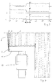
- FIG. 1 shows diagrams with processing-specific measured values of a plow furrow.
- a device 5 according to the invention is mounted above a furrow on a processing device, here a plow 4.
- the device 5 works with a laser beam which is pivoted over a swivel angle ⁇ of +/- 6 ° to the direction of travel.
- the profile (axis designation P) of a furrow is shown in the lower line diagram in FIG. In the range from -6 ° to -2 ° you can see the section through the processed field section 1. From -2 ° to 0 ° the depression in the field profile is indicated by a furrow.
- the subsequent field section from 0 ° to 6 ° represents the somewhat lower unprocessed field section 2.
- the associated distance measurement result E of the device 5 is shown schematically. Due to the attachment position on the work machine, elevations in the profile P have the effect of shortening the distance.
- the representation of the intensity I in the diagram above in FIG. 1 is approximately inversely related to the distance measurement diagram E.
- the intensity I of the reflection of the laser beam is higher on the processed field section 1 than on the unprocessed field section 2. Only the point at which the largest jump occurs is of interest for evaluating the values. For this reason, the measured values of a device working width have been standardized to the smallest values as a reference variable and have been presented without a unit. All subsequent measurements can be compared and used to identify the guideline.
- FIG. 2 shows a top view of a tractor 3 with an attached plow 4.
- a device 5 is attached to the plow 4 directly above the processing limit 8.
- the device is automatically brought into its working position after the plow rotation.
- FIG. 3 shows diagrams similar to FIG. 1.
- the profile P is shown by a mowing edge, based on a swivel angle range ⁇ of a device 5 according to the invention.
- the diagrams E and I above show the results of a measurement over an entire swivel angle range.
- the harvested field piece 2 is shown in the range from -6 ° to -1 °.
- the range -1 ° to + 6 ° represents a standing crop 1.
- the harvested field is recognized by the distance measurement E by the larger distance values and the standing crop 2 by the shorter distance values. When evaluating the intensity, the relationships are exactly the opposite.
- the evaluation process determines the jump points and assigns them to a swivel angle and calculates the actual position of the processing limit to the current direction of travel. It can be derived from FIG. 3 that the current direction of travel of the harvesting machine and the course of the processing edge differ by 1 °. Consequently, a control variable must be generated from this control deviation, which enables the driven machine to be returned to its required target course.
- FIG. 4 shows the top view of a harvesting machine 10 in use.
- a cutting device 11 according to the invention is mounted on the left-hand side of the cutting device 11.
- the Electromagnetic waves, here in the form of a laser beam 6, are in the direction of travel before Cutting unit 11 pivoted over the processing limit.
- the location of the device 5 is selected on the cutter 11 so that the device working width center is at a desired one Header utilization is exactly on the processing limit.
- a measured variable (here the distance) is represented by individual measured values 12 at to which the distance values E are assigned a swivel angle ⁇ .
- a measurement curve is obtained over a swivel range 9 of the device 5
- Deriving the distance according to the swivel angle then provides information about the relative position the largest jump in measured values or the processing limit for the direction of travel of the harvesting machine.
- the distance measurement result is shown on a swivel range Mowing edge shown.
- the processing limit here is at the point of the measured value jump 13 at a swivel angle of approx. -2.8 °.
- FIG. 6 several measured values are shown in a diagram over a device working width of two processing parameters specific to the processing limit.
- the distance E and, on the other hand, the intensity I of each measuring point are shown over the swivel angle ⁇ .
- the combination of the individual measured variables makes it possible to reliably recognize a guide track even with curve profiles that are difficult to analyze.
- both curves have a maximum value at the same point.
Landscapes
- Life Sciences & Earth Sciences (AREA)
- Environmental Sciences (AREA)
- Engineering & Computer Science (AREA)
- Mechanical Engineering (AREA)
- Soil Sciences (AREA)
- Guiding Agricultural Machines (AREA)
- Control Of Position, Course, Altitude, Or Attitude Of Moving Bodies (AREA)
Applications Claiming Priority (2)
| Application Number | Priority Date | Filing Date | Title |
|---|---|---|---|
| DE19743884A DE19743884C2 (de) | 1997-10-04 | 1997-10-04 | Vorrichtung und Verfahren zur berührungslosen Erkennung von Bearbeitungsgrenzen oder entsprechenden Leitgrößen |
| DE19743884 | 1997-10-04 |
Publications (3)
| Publication Number | Publication Date |
|---|---|
| EP0906720A1 true EP0906720A1 (fr) | 1999-04-07 |
| EP0906720B1 EP0906720B1 (fr) | 2003-11-05 |
| EP0906720B2 EP0906720B2 (fr) | 2006-07-12 |
Family
ID=7844592
Family Applications (1)
| Application Number | Title | Priority Date | Filing Date |
|---|---|---|---|
| EP98115144A Expired - Lifetime EP0906720B2 (fr) | 1997-10-04 | 1998-08-12 | Appareil et méthode pour la reconnaissance sans contact des limites de la zone de travail ou de sa taille correspondante |
Country Status (6)
| Country | Link |
|---|---|
| US (1) | US6095254A (fr) |
| EP (1) | EP0906720B2 (fr) |
| BR (1) | BR9803986B1 (fr) |
| DE (2) | DE19743884C2 (fr) |
| RU (1) | RU2215389C2 (fr) |
| UA (1) | UA57730C2 (fr) |
Cited By (4)
| Publication number | Priority date | Publication date | Assignee | Title |
|---|---|---|---|---|
| WO2001050835A1 (fr) * | 2000-01-12 | 2001-07-19 | Eco-Dan A/S | Traçage de sillon au laser |
| EP1125489A1 (fr) * | 2000-02-19 | 2001-08-22 | Lemken GmbH & Co. KG | Procédé pour le labour sur le champ et charrue réversible adjoint |
| WO2008064800A1 (fr) * | 2006-11-27 | 2008-06-05 | Carl Zeiss Microimaging Gmbh | Procédé et dispositif de commande d'un véhicule |
| US11291153B2 (en) * | 2017-03-17 | 2022-04-05 | Lemken Gmbh & Co. Kg | Method for planning the working of an agricultural field |
Families Citing this family (43)
| Publication number | Priority date | Publication date | Assignee | Title |
|---|---|---|---|---|
| DE19726917A1 (de) * | 1997-06-25 | 1999-01-07 | Claas Selbstfahr Erntemasch | Vorrichtung an Landmaschinen zur berührungslosen Abtastung von sich über den Boden erstreckenden Konturen |
| SE9704398L (sv) * | 1997-11-28 | 1998-12-14 | Spectra Precision Ab | Anordning och förfarande för att bestämma läget för bearbetande del |
| DE19830858A1 (de) | 1998-07-10 | 2000-01-13 | Claas Selbstfahr Erntemasch | Vorrichtung und Verfahren zur Bestimmung einer virtuellen Position |
| DE19845666B4 (de) | 1998-10-05 | 2005-08-25 | Claas Selbstfahrende Erntemaschinen Gmbh | Lenkautomatik mit Ultraschall-Ortungsvorrichtung |
| US6115481A (en) | 1998-10-22 | 2000-09-05 | Centrak, Llc | User modifiable land management zones for the variable application of substances thereto |
| DE19853085B4 (de) * | 1998-11-18 | 2014-03-20 | Claas Selbstfahrende Erntemaschinen Gmbh | Verfahren zum Justieren einer an einer Feldmaschine befestigten Sensoreinheit sowie eine Justiereinrichtung und eine Feldmaschine |
| DE10129135B4 (de) | 2001-06-16 | 2013-10-24 | Deere & Company | Einrichtung zur Positionsbestimmung eines landwirtschaftlichen Arbeitsfahrzeugs sowie ein landwirtschaftliches Arbeitsfahrzeug mit dieser |
| DE10129136A1 (de) | 2001-06-16 | 2002-12-19 | Deere & Co | Einrichtung zur selbsttätigen Lenkung eines landwirtschaftlichen Arbeitsfahrzeugs |
| DE10129133A1 (de) | 2001-06-16 | 2002-12-19 | Deere & Co | Einrichtung zur selbsttätigen Lenkung eines landwirtschaftlichen Arbeitsfahrzeugs |
| DE10130665A1 (de) * | 2001-06-28 | 2003-01-23 | Deere & Co | Vorrichtung zur Messung der Menge von auf einem Feld stehenden Pflanzen |
| US6615570B2 (en) * | 2001-06-28 | 2003-09-09 | Deere & Company | Header position control with forward contour prediction |
| US6661524B2 (en) * | 2001-07-09 | 2003-12-09 | United Defense, L.P. | Vehicle regional scanner |
| DE10204702A1 (de) * | 2002-02-05 | 2003-08-14 | Claas Selbstfahr Erntemasch | Ortungssystem an selbstfahrenden landwirtschaftlichen Arbeitsmaschinen |
| DE10208012A1 (de) * | 2002-02-26 | 2003-09-04 | Claas Selbstfahr Erntemasch | Spurführungssystem an einer landwirtschaftlichen Arbeitsmaschine |
| DE10227484A1 (de) * | 2002-06-19 | 2004-02-26 | Claas Selbstfahrende Erntemaschinen Gmbh | Vorrichtung und Verfahren zur Lagesteuerung eines Erntegutaufnahmegerätes landwirtschaftlicher Erntemaschinen |
| CA2427416C (fr) * | 2003-05-01 | 2010-11-16 | 101039130 Saskatchewan Ltd. | Dispositif de direction pour outils remorques |
| US20050076716A1 (en) * | 2003-09-05 | 2005-04-14 | Steven Turner | Method and apparatus for detecting guideway breaks and occupation |
| US7916898B2 (en) * | 2003-09-15 | 2011-03-29 | Deere & Company | Method and system for identifying an edge of a crop |
| DE102004011789A1 (de) * | 2004-03-09 | 2005-09-29 | Claas Selbstfahrende Erntemaschinen Gmbh | Vorrichtung zum Erfassen eines Ladewagens |
| US7412905B1 (en) | 2004-05-31 | 2008-08-19 | Richard Anthony Bishel | Paddle sensor |
| US7168174B2 (en) * | 2005-03-14 | 2007-01-30 | Trimble Navigation Limited | Method and apparatus for machine element control |
| DE102005047306A1 (de) | 2005-09-30 | 2007-04-12 | Claas Saulgau Gmbh | Landwirtschaftliche Arbeitseinheit mit einem Arbeitsaggregat zum Erzeugen einer Objektreihe |
| DE102006019216A1 (de) | 2006-04-21 | 2007-10-25 | Claas Selbstfahrende Erntemaschinen Gmbh | Verfahren zur Steuerung eines landwirtschaftlichen Maschinensystems |
| US8060299B2 (en) * | 2007-02-28 | 2011-11-15 | Caterpillar Inc. | Machine with automated steering system |
| US8275506B1 (en) | 2008-06-08 | 2012-09-25 | Richard Anthony Bishel | Boundary sensor |
| DE102008056557A1 (de) * | 2008-11-10 | 2010-05-12 | Claas Selbstfahrende Erntemaschinen Gmbh | Erstellung von Bilddatenbanken für Bildauswertung |
| DE102008043716B4 (de) | 2008-11-13 | 2012-06-21 | Deere & Company | Vorrichtung und Verfahren zur Erfassung der Bestandsdichte von Pflanzen auf einem Feld |
| US9668400B2 (en) * | 2011-07-05 | 2017-06-06 | Kongskilde Industries A/S | Automatic guidance system for pull-type agricultural implement |
| DE102013101016A1 (de) * | 2013-02-01 | 2014-08-07 | Claas Selbstfahrende Erntemaschinen Gmbh | Selbstfahrende landwirtschaftliche Erntemaschine, insbesondere Feldhäcksler |
| CN103155758B (zh) * | 2013-03-12 | 2016-08-10 | 上海大学 | 无人驾驶联合收割机的激光导航系统 |
| RU2607337C1 (ru) * | 2015-07-10 | 2017-01-10 | Федеральное государственное бюджетное образовательное учреждение высшего профессионального образования Новосибирский государственный аграрный университет | Способ местоопределения тракторного агрегата и устройство для осуществления |
| DE102015118767A1 (de) * | 2015-11-03 | 2017-05-04 | Claas Selbstfahrende Erntemaschinen Gmbh | Umfelddetektionseinrichtung für landwirtschaftliche Arbeitsmaschine |
| US9854725B2 (en) | 2016-03-28 | 2018-01-02 | Cnh Industrial America Llc | Laser guidance system for agricultural operations |
| DE102016209437A1 (de) | 2016-05-31 | 2017-11-30 | Deere & Company | Selbsttätiges Lenksystem zur Führung eines landwirtschaftlichen Fahrzeugs über ein Feld und entsprechendes Verfahren |
| DE102016216515A1 (de) * | 2016-09-01 | 2018-03-01 | Deere & Company | Anordnung zur Beeinflussung der Lage eines landwirtschaftlichen Anbaugeräts |
| GB201704967D0 (en) | 2017-03-28 | 2017-05-10 | Agco Feucht Gmbh | Steering assistance system for an agricultural tractor and implement combination |
| US10532747B2 (en) | 2017-12-04 | 2020-01-14 | Deere & Company | System and method for automatic detection of implement working width |
| DE102018102310A1 (de) * | 2018-02-01 | 2019-08-01 | Claas Saulgau Gmbh | Verfahren und Steuergerät zum Betreiben eines Kreiselschwaders sowie Kreiselschwader |
| US10750656B2 (en) | 2018-06-29 | 2020-08-25 | Cnh Industrial America Llc | System and method for monitoring the frame levelness of an agricultural implement |
| DE102019203247A1 (de) * | 2019-03-11 | 2020-09-17 | Zf Friedrichshafen Ag | Vision-basiertes Lenkungsassistenzsystem für Landfahrzeuge |
| US11202410B2 (en) | 2019-04-30 | 2021-12-21 | Deere & Company | Light-emitting mechanism on crop divider rod of harvesting header |
| US11575810B2 (en) | 2020-09-09 | 2023-02-07 | Deere & Company | Auto-positioning camera for drawn implements |
| DE102022129533A1 (de) | 2021-12-01 | 2023-06-01 | Wiedenmann Gmbh | Vorrichtung und Verfahren zur Rasenpflege mit Spurerkennung |
Citations (10)
| Publication number | Priority date | Publication date | Assignee | Title |
|---|---|---|---|---|
| DE2423689A1 (de) * | 1974-05-15 | 1975-11-27 | Maschf Augsburg Nuernberg Ag | Automatische lenkung eines kraftfahrzeugs |
| DE2455836A1 (de) | 1974-11-26 | 1976-08-12 | Claas Maschf Gmbh Geb | Einrichtung zur selbsttaetigen fuehrung landwirtschaftlicher arbeitsmaschinen |
| DD264366A1 (de) | 1986-11-14 | 1989-02-01 | Traktoren Und Dieselmotorenwer | Verfahren und anordnung der positionsbestimmung zu bearbeitungsgrenzen und pflanzenreihen |
| US5509486A (en) * | 1994-08-12 | 1996-04-23 | Loral Corporation | Method of steering an agricultural vehicle |
| DE19508941A1 (de) | 1995-03-13 | 1996-09-19 | Claas Ohg | Ortungsvorrichtung |
| DE19508942A1 (de) | 1995-03-13 | 1996-09-19 | Claas Ohg | Reflex-Ortungsvorrichtung |
| EP0801885A1 (fr) * | 1996-04-19 | 1997-10-22 | Carnegie-Mellon University | Guidage par rapport à ligne de récolte basé sur la vision |
| EP0843959A1 (fr) * | 1996-11-21 | 1998-05-27 | CLAAS KGaA | Dispositif de mesure des paramètres dans une machine agricole |
| EP0878121A1 (fr) * | 1997-05-13 | 1998-11-18 | CLAAS KGaA | Machine de récolte à direction automatique |
| EP0887660A2 (fr) * | 1997-06-25 | 1998-12-30 | CLAAS Selbstfahrende Erntemaschinen GmbH | Dispositif à montage sur engins agricoles pour le balayage sans contact de contours sur la surface de la terre |
Family Cites Families (21)
| Publication number | Priority date | Publication date | Assignee | Title |
|---|---|---|---|---|
| GB1582415A (en) * | 1978-03-22 | 1981-01-07 | Energystics Corp | Vehicle guidance system |
| DE3300086A1 (de) * | 1983-01-04 | 1984-07-05 | Roman 7981 Schlier Gmünder | Einrichtung zur warnung von kraftfahrern |
| US4716414A (en) * | 1984-05-10 | 1987-12-29 | The Secretary Of State For Defence In Her Britannic Majesty's Government Of The United Kingdom Of Great Britain And Northern Ireland | Super resolution imaging system |
| DE3638134A1 (de) * | 1986-11-08 | 1988-05-11 | Lutz Gmbh Haus Der Landtechnik | Ruebenvollerntemaschine |
| US5019983A (en) * | 1989-02-21 | 1991-05-28 | Eaton Corporation | Automatic steering apparatus using reflected signals |
| DE4004247A1 (de) * | 1990-02-12 | 1991-08-14 | Feser Werner | Servo-geregeltes bearbeitungs-grundgeraet mit elektronischer pflanzenabtastung |
| US5293162A (en) * | 1992-03-09 | 1994-03-08 | Bachalo William D | Laser based tracking device for detecting the distance between a vehicle and a roadway marker |
| US5410479A (en) * | 1992-08-17 | 1995-04-25 | Coker; William B. | Ultrasonic furrow or crop row following sensor |
| DE4318798A1 (de) * | 1992-11-24 | 1994-06-01 | Holger Muehlberger | Automatisch selbstfahrende Arbeitsmaschine zur Bearbeitung von definierten Flächen |
| US5430654A (en) * | 1992-12-01 | 1995-07-04 | Caterpillar Inc. | Method and apparatus for improving the accuracy of position estimates in a satellite based navigation system |
| DE4322293C2 (de) * | 1993-07-05 | 2003-05-28 | Amazonen Werke Dreyer H | Verfahren zum elektronischen Managen von landwirtschaftlichen Maschinen |
| US5528888A (en) * | 1993-12-27 | 1996-06-25 | Fuji Jukogyo Kabushiki Kaisha | Autonomous mowing vehicle and apparatus for detecting boundary of mowed field |
| JPH07209080A (ja) * | 1993-12-28 | 1995-08-11 | Amberg Measuring Technik Ltd | 光学走査装置 |
| DE4406892A1 (de) * | 1994-03-03 | 1995-09-07 | Bosch Gmbh Robert | Vorrichtung zur Regelung des Bodenabstandes einer Bearbeitungseinheit einer landwirtschaftlichen Maschine |
| DE4431824C1 (de) * | 1994-09-07 | 1996-05-02 | Claas Ohg | Mähdrescherbetrieb mit Betriebsdatenkataster |
| US5666792A (en) * | 1994-12-30 | 1997-09-16 | Mullins; Donald B. | Remotely guided brush cutting, chipping and clearing apparatus and method |
| DE69609362T2 (de) * | 1995-01-25 | 2000-12-07 | Agco Ltd | Erntemaschine |
| DE19508944A1 (de) * | 1995-03-13 | 1996-09-19 | Claas Ohg | Selbstlenkvorrichtung |
| DE19518058C2 (de) * | 1995-05-17 | 1999-08-19 | Jacoby Gmbh & Co Kg M | Vorrichtung zum Besprühen von Raumkulturen |
| US5612864A (en) * | 1995-06-20 | 1997-03-18 | Caterpillar Inc. | Apparatus and method for determining the position of a work implement |
| US5782072A (en) * | 1996-07-11 | 1998-07-21 | Matthews; H. Wayne | Crop tracking row units on cotton harvesters |
-
1997
- 1997-10-04 DE DE19743884A patent/DE19743884C2/de not_active Revoked
-
1998
- 1998-08-12 DE DE59810071T patent/DE59810071D1/de not_active Expired - Lifetime
- 1998-08-12 EP EP98115144A patent/EP0906720B2/fr not_active Expired - Lifetime
- 1998-09-30 US US09/163,843 patent/US6095254A/en not_active Expired - Lifetime
- 1998-10-02 UA UA98105218A patent/UA57730C2/uk unknown
- 1998-10-02 BR BRPI9803986-5A patent/BR9803986B1/pt not_active IP Right Cessation
- 1998-10-05 RU RU98118502/13A patent/RU2215389C2/ru not_active IP Right Cessation
Patent Citations (13)
| Publication number | Priority date | Publication date | Assignee | Title |
|---|---|---|---|---|
| DE2423689A1 (de) * | 1974-05-15 | 1975-11-27 | Maschf Augsburg Nuernberg Ag | Automatische lenkung eines kraftfahrzeugs |
| DE2455836A1 (de) | 1974-11-26 | 1976-08-12 | Claas Maschf Gmbh Geb | Einrichtung zur selbsttaetigen fuehrung landwirtschaftlicher arbeitsmaschinen |
| DD264366A1 (de) | 1986-11-14 | 1989-02-01 | Traktoren Und Dieselmotorenwer | Verfahren und anordnung der positionsbestimmung zu bearbeitungsgrenzen und pflanzenreihen |
| US5509486A (en) * | 1994-08-12 | 1996-04-23 | Loral Corporation | Method of steering an agricultural vehicle |
| US5715666A (en) * | 1995-03-13 | 1998-02-10 | Claas Kommanditgesellschaft Auf Aktien | Reflex locating device |
| DE19508941A1 (de) | 1995-03-13 | 1996-09-19 | Claas Ohg | Ortungsvorrichtung |
| DE19508942A1 (de) | 1995-03-13 | 1996-09-19 | Claas Ohg | Reflex-Ortungsvorrichtung |
| US5715665A (en) * | 1995-03-13 | 1998-02-10 | Claas Kommanditgesellschaft Auf Aktien | Locating device for an automatic steering system of an agricultural vehicle |
| EP0801885A1 (fr) * | 1996-04-19 | 1997-10-22 | Carnegie-Mellon University | Guidage par rapport à ligne de récolte basé sur la vision |
| EP0843959A1 (fr) * | 1996-11-21 | 1998-05-27 | CLAAS KGaA | Dispositif de mesure des paramètres dans une machine agricole |
| EP0878121A1 (fr) * | 1997-05-13 | 1998-11-18 | CLAAS KGaA | Machine de récolte à direction automatique |
| EP0887660A2 (fr) * | 1997-06-25 | 1998-12-30 | CLAAS Selbstfahrende Erntemaschinen GmbH | Dispositif à montage sur engins agricoles pour le balayage sans contact de contours sur la surface de la terre |
| DE19726917A1 (de) | 1997-06-25 | 1999-01-07 | Claas Selbstfahr Erntemasch | Vorrichtung an Landmaschinen zur berührungslosen Abtastung von sich über den Boden erstreckenden Konturen |
Cited By (4)
| Publication number | Priority date | Publication date | Assignee | Title |
|---|---|---|---|---|
| WO2001050835A1 (fr) * | 2000-01-12 | 2001-07-19 | Eco-Dan A/S | Traçage de sillon au laser |
| EP1125489A1 (fr) * | 2000-02-19 | 2001-08-22 | Lemken GmbH & Co. KG | Procédé pour le labour sur le champ et charrue réversible adjoint |
| WO2008064800A1 (fr) * | 2006-11-27 | 2008-06-05 | Carl Zeiss Microimaging Gmbh | Procédé et dispositif de commande d'un véhicule |
| US11291153B2 (en) * | 2017-03-17 | 2022-04-05 | Lemken Gmbh & Co. Kg | Method for planning the working of an agricultural field |
Also Published As
| Publication number | Publication date |
|---|---|
| DE19743884A1 (de) | 1999-04-08 |
| RU2215389C2 (ru) | 2003-11-10 |
| BR9803986B1 (pt) | 2008-11-18 |
| EP0906720B1 (fr) | 2003-11-05 |
| BR9803986A (pt) | 1999-12-07 |
| UA57730C2 (uk) | 2003-07-15 |
| DE59810071D1 (de) | 2003-12-11 |
| US6095254A (en) | 2000-08-01 |
| DE19743884C2 (de) | 2003-10-09 |
| EP0906720B2 (fr) | 2006-07-12 |
Similar Documents
| Publication | Publication Date | Title |
|---|---|---|
| EP0906720B1 (fr) | Appareil et méthode pour la reconnaissance sans contact des limites de la zone de travail ou de sa taille correspondante | |
| EP3165062B1 (fr) | Machine de travail agricole avec un dispositif de détection d'environnement | |
| EP0878121B2 (fr) | Machine de récolte à direction automatique | |
| EP1356729B1 (fr) | Dispositif de mesure pour machine agricole | |
| EP1630574B1 (fr) | Dispositif monté sur des machines agricoles destiné au balayage sans contact de contours sýétendant sur le sol | |
| DE102005015615B4 (de) | Verfahren und Vorrichtung zur Steuerung eines Arbeitskopfes | |
| EP0732045B1 (fr) | Dispositif de reflex-orientation | |
| DE10204702A1 (de) | Ortungssystem an selbstfahrenden landwirtschaftlichen Arbeitsmaschinen | |
| DE10129136A1 (de) | Einrichtung zur selbsttätigen Lenkung eines landwirtschaftlichen Arbeitsfahrzeugs | |
| EP3300561B1 (fr) | Machine agricole automotrice | |
| EP0732046A1 (fr) | Dispositif d'orientation | |
| EP3738420B1 (fr) | Procédé de fonctionnement d'un engin agricole automatique | |
| EP3530098B1 (fr) | Procédé de détermination de la densité de pâturage d'une culture | |
| EP3530099B1 (fr) | Moissonneuse automotrice | |
| EP4052550B1 (fr) | Dispositif de compensation de la suspension latérale pour la viticulture | |
| DE2654141A1 (de) | Selbstfahrende erntemaschine | |
| EP1862049A1 (fr) | Machine agricole | |
| DE102018204301B4 (de) | Verfahren zum Ermitteln einer Bestandhöhe von Feldpflanzen | |
| EP4155775A1 (fr) | Procédé d'identification d'objets, ainsi que machine de travail agricole | |
| EP4154698A1 (fr) | Procédé de détection du niveau du sol sur une surface à traiter par une machine de travail agricole | |
| DE102021124478A1 (de) | Verfahren zur Fruchtartunterscheidung von Pflanzen innerhalb eines Feldbestandes | |
| AT523999A1 (de) | Vorrichtung an Landmaschinen zur Abtastung von Konturen sowie Verfahren zur Steuerung der Landmaschine | |
| EP2057875A1 (fr) | Procédé et agencement destinés à l'établissement de la constitution de plantes sur des machines agricoles |
Legal Events
| Date | Code | Title | Description |
|---|---|---|---|
| PUAI | Public reference made under article 153(3) epc to a published international application that has entered the european phase |
Free format text: ORIGINAL CODE: 0009012 |
|
| AK | Designated contracting states |
Kind code of ref document: A1 Designated state(s): BE DE DK FR GB IT NL |
|
| AX | Request for extension of the european patent |
Free format text: AL;LT;LV;MK;RO;SI |
|
| 17P | Request for examination filed |
Effective date: 19991007 |
|
| AKX | Designation fees paid |
Free format text: BE DE DK FR GB IT NL |
|
| 17Q | First examination report despatched |
Effective date: 20020214 |
|
| GRAH | Despatch of communication of intention to grant a patent |
Free format text: ORIGINAL CODE: EPIDOS IGRA |
|
| GRAS | Grant fee paid |
Free format text: ORIGINAL CODE: EPIDOSNIGR3 |
|
| GRAA | (expected) grant |
Free format text: ORIGINAL CODE: 0009210 |
|
| AK | Designated contracting states |
Kind code of ref document: B1 Designated state(s): BE DE DK FR GB IT NL |
|
| PG25 | Lapsed in a contracting state [announced via postgrant information from national office to epo] |
Ref country code: NL Free format text: LAPSE BECAUSE OF FAILURE TO SUBMIT A TRANSLATION OF THE DESCRIPTION OR TO PAY THE FEE WITHIN THE PRESCRIBED TIME-LIMIT Effective date: 20031105 Ref country code: IT Free format text: LAPSE BECAUSE OF FAILURE TO SUBMIT A TRANSLATION OF THE DESCRIPTION OR TO PAY THE FEE WITHIN THE PRE;WARNING: LAPSES OF ITALIAN PATENTS WITH EFFECTIVE DATE BEFORE 2007 MAY HAVE OCCURRED AT ANY TIME BEFORE 2007. THE CORRECT EFFECTIVE DATE MAY BE DIFFERENT FROM THE ONE RECORDED.SCRIBED TIME-LIMIT Effective date: 20031105 |
|
| REG | Reference to a national code |
Ref country code: GB Ref legal event code: FG4D Free format text: NOT ENGLISH |
|
| REF | Corresponds to: |
Ref document number: 59810071 Country of ref document: DE Date of ref document: 20031211 Kind code of ref document: P |
|
| GBT | Gb: translation of ep patent filed (gb section 77(6)(a)/1977) |
Effective date: 20031205 |
|
| PG25 | Lapsed in a contracting state [announced via postgrant information from national office to epo] |
Ref country code: DK Free format text: LAPSE BECAUSE OF FAILURE TO SUBMIT A TRANSLATION OF THE DESCRIPTION OR TO PAY THE FEE WITHIN THE PRESCRIBED TIME-LIMIT Effective date: 20040205 |
|
| NLV1 | Nl: lapsed or annulled due to failure to fulfill the requirements of art. 29p and 29m of the patents act | ||
| ET | Fr: translation filed | ||
| PLBQ | Unpublished change to opponent data |
Free format text: ORIGINAL CODE: EPIDOS OPPO |
|
| PLBI | Opposition filed |
Free format text: ORIGINAL CODE: 0009260 |
|
| PLAX | Notice of opposition and request to file observation + time limit sent |
Free format text: ORIGINAL CODE: EPIDOSNOBS2 |
|
| 26 | Opposition filed |
Opponent name: DEERE & COMPANY Effective date: 20040727 |
|
| PLBB | Reply of patent proprietor to notice(s) of opposition received |
Free format text: ORIGINAL CODE: EPIDOSNOBS3 |
|
| PUAH | Patent maintained in amended form |
Free format text: ORIGINAL CODE: 0009272 |
|
| STAA | Information on the status of an ep patent application or granted ep patent |
Free format text: STATUS: PATENT MAINTAINED AS AMENDED |
|
| 27A | Patent maintained in amended form |
Effective date: 20060712 |
|
| AK | Designated contracting states |
Kind code of ref document: B2 Designated state(s): BE DE DK FR GB IT NL |
|
| GBTA | Gb: translation of amended ep patent filed (gb section 77(6)(b)/1977) |
Effective date: 20060830 |
|
| ET3 | Fr: translation filed ** decision concerning opposition | ||
| REG | Reference to a national code |
Ref country code: FR Ref legal event code: PLFP Year of fee payment: 18 |
|
| PGFP | Annual fee paid to national office [announced via postgrant information from national office to epo] |
Ref country code: GB Payment date: 20150824 Year of fee payment: 18 Ref country code: DE Payment date: 20150617 Year of fee payment: 18 |
|
| PGFP | Annual fee paid to national office [announced via postgrant information from national office to epo] |
Ref country code: FR Payment date: 20150824 Year of fee payment: 18 Ref country code: BE Payment date: 20150820 Year of fee payment: 18 |
|
| PG25 | Lapsed in a contracting state [announced via postgrant information from national office to epo] |
Ref country code: BE Free format text: LAPSE BECAUSE OF NON-PAYMENT OF DUE FEES Effective date: 20160831 |
|
| REG | Reference to a national code |
Ref country code: DE Ref legal event code: R119 Ref document number: 59810071 Country of ref document: DE |
|
| GBPC | Gb: european patent ceased through non-payment of renewal fee |
Effective date: 20160812 |
|
| REG | Reference to a national code |
Ref country code: FR Ref legal event code: ST Effective date: 20170428 |
|
| PG25 | Lapsed in a contracting state [announced via postgrant information from national office to epo] |
Ref country code: FR Free format text: LAPSE BECAUSE OF NON-PAYMENT OF DUE FEES Effective date: 20160831 Ref country code: DE Free format text: LAPSE BECAUSE OF NON-PAYMENT OF DUE FEES Effective date: 20170301 Ref country code: GB Free format text: LAPSE BECAUSE OF NON-PAYMENT OF DUE FEES Effective date: 20160812 |