EP0905447B1 - Dispositif de vaporisation pour combustibles liquides - Google Patents
Dispositif de vaporisation pour combustibles liquides Download PDFInfo
- Publication number
- EP0905447B1 EP0905447B1 EP98117444A EP98117444A EP0905447B1 EP 0905447 B1 EP0905447 B1 EP 0905447B1 EP 98117444 A EP98117444 A EP 98117444A EP 98117444 A EP98117444 A EP 98117444A EP 0905447 B1 EP0905447 B1 EP 0905447B1
- Authority
- EP
- European Patent Office
- Prior art keywords
- capillary tube
- tube
- heating
- fuel
- inside diameter
- Prior art date
- Legal status (The legal status is an assumption and is not a legal conclusion. Google has not performed a legal analysis and makes no representation as to the accuracy of the status listed.)
- Expired - Lifetime
Links
Images


Classifications
-
- F—MECHANICAL ENGINEERING; LIGHTING; HEATING; WEAPONS; BLASTING
- F23—COMBUSTION APPARATUS; COMBUSTION PROCESSES
- F23K—FEEDING FUEL TO COMBUSTION APPARATUS
- F23K5/00—Feeding or distributing other fuel to combustion apparatus
- F23K5/02—Liquid fuel
- F23K5/14—Details thereof
- F23K5/22—Vaporising devices
-
- F—MECHANICAL ENGINEERING; LIGHTING; HEATING; WEAPONS; BLASTING
- F23—COMBUSTION APPARATUS; COMBUSTION PROCESSES
- F23D—BURNERS
- F23D11/00—Burners using a direct spraying action of liquid droplets or vaporised liquid into the combustion space
- F23D11/36—Details, e.g. burner cooling means, noise reduction means
- F23D11/40—Mixing tubes or chambers; Burner heads
- F23D11/408—Flow influencing devices in the air tube
-
- F—MECHANICAL ENGINEERING; LIGHTING; HEATING; WEAPONS; BLASTING
- F23—COMBUSTION APPARATUS; COMBUSTION PROCESSES
- F23D—BURNERS
- F23D11/00—Burners using a direct spraying action of liquid droplets or vaporised liquid into the combustion space
- F23D11/36—Details, e.g. burner cooling means, noise reduction means
- F23D11/44—Preheating devices; Vaporising devices
- F23D11/441—Vaporising devices incorporated with burners
- F23D11/448—Vaporising devices incorporated with burners heated by electrical means
Definitions
- the invention relates to a device for vaporizing liquid fuels according to the preamble of claim 1.
- the residue-free evaporation of liquid hydrocarbon fuels such as. Heating oil and diesel fuel in the Gram range represents a previously unsatisfactorily solved technical problem.
- the evaporation of such fuels runs in a temperature range of 160 to 380 ° C, what a complete evaporation temperatures of the heat transfer surfaces of more than 200 to 450 ° C is required.
- whisker threads e.g. H. Schladitz "Fuel Processing and Environmental Protection” in “Oil and gas firing", 1973, Issue 3, page 164 to 168.
- the whisker mesh forms a structure with a high Porosity and thus a large pore volume and a large one Heat transfer surface.
- the metallic whisker threads can be used directly as electrical resistance heating become.
- the flow through the fine-pored structure leads to Connection with the relatively large volume to long dwell times of fuel, which in turn is the deposit of higher-boiling or solid components and cracked macromolecules in the porous whisker skeleton.
- DE-A-3 403 471 and DE-A-3 516 410 an evaporator known in the liquid fuel through an indirectly heated capillary tube in which the fuel is either is preheated or partially evaporated.
- the invention has for its object a device for To provide vaporization of liquid fuels the most residue-free evaporation smaller and smallest quantities of liquid fuels in the gram range allows.
- the main idea of the invention is the liquid Vaporizing fuel in a heatable capillary tube where the inside diameter of the capillary tube as possible is kept small. To the necessary heat transfer area to get the length of the capillary tube accordingly large size. To despite the great length of the capillary tube produce an evaporator with small dimensions To be able to, the capillary tube is preferably in turns arranged to a large length of the capillary tube in one to accommodate small volumes.
- the heating of the capillary tube can either be done directly by the capillary tube itself is used as a heating conductor, or indirectly by using the Capillary tube is in contact with a heating cartridge.
- the capillary tube has an inner diameter from about 0.3 to 2.0 mm, preferably from 0.5 to 1.3 mm.
- the ratio of the length of the capillary tube to its inside diameter is in the range of about 500 to 3000, preferably from 900 to 2300. Given this dimensioning the residence times of the fuel in the capillary tube are in the millisecond range.
- the low-boiling fractions evaporate first and form an axial steam flow in the capillary. Die Abursiedenden Fractions are thereby against the wall of the Capillary tube pushed so that they are heated more intensely. The entrainment of the high-boiling fractions at speeds up to 160 m / s prevent deposits of residual fractions.
- the capillary tube has an overheating length, in which also the required minimum system pressure from about 1 to 2 bar.
- the capillary tube evaporator according to the invention can in all Use cases are used in which one if possible residue-free evaporation of hydrocarbon mixtures is sought.
- the device can be used as a heating oil evaporator for aerosol formation with the combustion air in Premix burners are used.
- the capillary tube evaporator can be used for firing larger outputs can be used as pilot and pilot burners. Finally it can also be used as a preheater for heating oil Installation in pressure atomizer nozzle shafts.
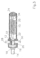
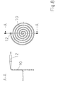
- Fig. 1 shows a capillary tube as it is according to the invention for the Device for vaporizing hydrocarbon fuels, such as heating oil and diesel oil in a mass flow range of 0.1 up to 4.0 kg / h, preferably from 0.2 to 2.4 kg / h becomes.
- hydrocarbon fuels such as heating oil and diesel oil in a mass flow range of 0.1 up to 4.0 kg / h, preferably from 0.2 to 2.4 kg / h becomes.
- the capillary tube 10 has an inner diameter d that between 0.3 and 2.0 mm, preferably between 0.5 and 1.3 mm lies.
- the ratio of the wall thickness of the capillary tube 10 to the inside diameter is 0.2 to 0.5.
- the length L of the Capillary tube 10 is 500 to 3000 times the inner diameter d, preferably 900 to 2300 times.
- the wall of the capillary tube 10 is described in later Way heated.
- the liquid fuel Mf is in the capillary 10 initiated, flows through the capillary tube 10 and emerges from the capillary tube 10 as vapor MD.
- a first length section L1 on the entry side the liquid fuel supplied through the heated wall of the Capillary tube 10 heated to its boiling point.
- the fuel evaporates starting with the low boiling fractions.
- the last outlet-side length section L3 is the liquid one Fuel evaporates completely and is additionally overheated.
- the heating of the wall of the capillary tube 10 leads to a temporally fluctuating heat generation over the length the capillary tube 10.
- the temperature of the supplied liquid fuel This results in a axial position of the evaporation zone L2 which fluctuates over time.
- the the superheating zone L3 downstream of the evaporation zone L2 ensures that despite the fluctuations in the evaporation zone L2 the fuel reliably exits the capillary tube 10 is completely evaporated.
- the Overheating zone L3 ensures that the fuel vapor with stable flow and the required minimum system pressure from the capillary tube 10 exits from 1 to 2 bar.
- Figures 2 and 3 show a first embodiment of the device.
- the capillary tube 10 is helical bent into a spiral.
- the exit end the capillary tube 10 is bent so that it is in the The central axis of the spiral runs.
- the entry end of the Capillary tube 10 is also in the central axis of the coil bent.
- a transition tube piece closes at the inlet end 12, which serves to cross-section the Fuel supply line to the small cross section of the capillary tube 10 to reduce.
- the transition pipe section 12 goes on the entry side into a threaded sleeve 14, which with a Collar 16 and one on the external thread of the threaded sleeve 14 seated lock nut 18 for screwing the device in the bulkhead of a burner is used.
- FIG. 3 shows how the capillary tube 10 shown in FIG. 2 is installed in a complete evaporator.
- the coiled capillary tube 10 inserted into a protective sleeve 20, whose inner wall is insulated by an insulating sleeve 22.
- an insulating insert 24 used, the axis of the outlet side End of the capillary tube 10 is penetrated.
- the transition pipe piece 12 with the subsequent threaded sleeve 14 is centered held in an insulating body 26. Is on the entry side the protective sleeve 20 between the collar 16 and the lock nut 18th fixed on the threaded sleeve 14.
- the connector connection contact 28 is with a electrical guided axially parallel in the insulating body 26 Conductor 32 connected.
- This conductor 32 carries out axially parallel the coil of the capillary tube 10 and is with its front End set in the insulating insert 24.
- the front end of the Conductor 32 is directly behind the insulating insert 24 a terminal 34 electrically conductive with the outlet end of the capillary tube 10 connected.
- the second connector connector 30 leads radially through the insulating body 26 and contacts the transition tube piece in an electrically conductive manner 12th
- Capillary tube 10 can be connected to a power supply.
- the connector connector 28 the phase and to the connector terminal contact 30 the Ground of a low-voltage network of up to 42 V.
- the capillary tube 10 consists of a Heating conductor metal, e.g. made of a chrome-nickel steel.
- the capillary tube 10 is executed by the capillary tube 10 flowing current directly heated.
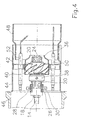
- FIG 4 shows the installation of the device of Figures 2 and 3 into a burner tube.
- the device is with its protective sleeve 20 coaxially inserted into the hub of an air nozzle 36, and by means of a clamping ring 38 set in the air nozzle 36.
- the Air nozzle 36 also has a hub coaxially surrounding the hub Swirl body 40.
- the air nozzle 36 is centered in one Schott 42 used, which in turn in a burner stem 44 sits and closes this except for the air nozzle 36.
- the burner main pipe 44 is connected to a burner blower socket 46 scheduled.
- a flame tube 48 is attached, which for generation an injector effect lateral recirculation openings having.
- a flame monitoring probe is also in the bulkhead 42 50 and a pair of ignition electrodes 52 are used.
- the structure of the burner tube is apart from the evaporator device known per se.
- FIG. 5 shows a modification of the installation situation in FIG. 4, in which the evaporator device is axially downstream extends beyond the air nozzle 36, with the air nozzle 36 axially a catch tube 54 is placed.
- the combustion air is Air nozzle 36 conical and by means of the swirl body 40 with swirl acted upon in the emerging from the capillary tube 10
- Fuel steam jet initiated to intensive mixing of combustion air and fuel vapor.
- the swirl is over combustion air supplied to the air nozzle 36 in the trap 54 steered so that it swirls over the widening downstream Catch pipe 54 emerges and with the fuel vapor mixed forms an expanding flame cone.
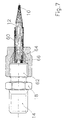
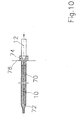
- Figures 6 and 7 show a modification of the first embodiment the device, the connection and installation of the helically bent capillary tube 10 are modified.
- the helically curved capillary tube sits 10 in an electrically conductive protective sleeve 56.
- Die Protective sleeve 56 is at its downstream end through a electrically conductive cap 58 completed, the centric Exit end of the capillary tube 10 receives, fixed and contacted electrically conductive. That on the entry side Transition tube piece 12 adjoining the end of the capillary tube 10 is inserted into an insulating bush 60.
- the insulating bush 60 with the transition pipe piece 12 is with the threaded sleeve 14th screwed.
- the threaded sleeve 14 has a connecting nipple 62 on which a union nut 64 with a conical clamping ring 66 is screwed on.
- An electric one Terminal contact 68 insulates the protective sleeve 56 and is conductive with the transition pipe section 12 and thus the Capillary tube 10 in connection.
- the connection contact 68 serves to connect the phase of the power supply while the Protective sleeve 56 establishes the ground connection.
- FIG. 8 shows a second embodiment of the capillary tube 10.
- the capillary tube 10 is not in the form of a Spiral but bent in the form of a spiral.
- the transition pipe piece 12 to supply the liquid fuel is there arranged at the outer end of the spiral, while the outlet end is arranged in the middle.
- FIG. 9 shows a third embodiment of the capillary tube 10.
- the capillary tube 10 is in several hairpin bends bent so that going back and forth parallel sections of the capillary tube 10 result.
- the hairpin bends can be bent so tight that you Radius of curvature R only three times the inner diameter d of the capillary tube is 10.
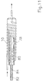
- FIG. 10 shows a fourth embodiment of the capillary tube 10, which differs in the electrical contact.
- the casing tube 70 has only one small outer diameter of e.g. 2 to 3 mm and is from the capillary tube 10 separated by insulation 72 which e.g. is designed as a thin film or varnish.
- insulation 72 which e.g. is designed as a thin film or varnish.
- the jacket tube 70 conductively connected to the capillary tube 10.
- An insulating plug 74 is provided at the end, one Connection contact 76 of the jacket tube 70 against the transition tube piece 12 electrically isolated, which is the second electrical Has contact.
- the capillary tube 10 with the jacket tube 70 can be bent and installed in any shape without that additional measures for electrical contacting and Power supply to the exit end of the capillary tube 10 are necessary.
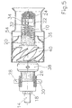
- the capillary tube 10 is designed as a heating conductor and heated directly 11 shows an embodiment in which the capillary tube 10 is indirectly heated.
- the material of the capillary tube 10 can therefore regardless of its electrical conductivity to get voted.
- the capillary tube 10 is helical on the outer surface of a cylindrical heat-conducting Sleeve 78 wrapped.
- a heating cartridge 80 with the electrical line connections 82 and 84 used.
- the heating cartridge 80 is heated via the thermally conductive sleeve 78, the capillary tube 10 indirectly.
- the heating cartridge 80 can in a manner known per se for high voltage or low voltage.
Landscapes
- Engineering & Computer Science (AREA)
- Chemical & Material Sciences (AREA)
- Combustion & Propulsion (AREA)
- Mechanical Engineering (AREA)
- General Engineering & Computer Science (AREA)
- Spray-Type Burners (AREA)
- Production Of Liquid Hydrocarbon Mixture For Refining Petroleum (AREA)
- Feeding And Controlling Fuel (AREA)
- Filling Or Discharging Of Gas Storage Vessels (AREA)
- Vaporization, Distillation, Condensation, Sublimation, And Cold Traps (AREA)
Claims (20)
- Dispositif de vaporisation de combustibles liquides comprenant un tube traversé par le combustible et dont la paroi peut être chauffée électriquement pour vaporiser le combustible,
caractérisé en ce que
le tube est un tube capillaire (10) dont le diamètre intérieur (d) est compris entre 0,3 et 2,0 mm et la longueur (L) représente entre 500 et 3000 fois le diamètre intérieur (d). - Dispositif selon la revendication 1,
caractérisé en ce que
le diamètre intérieur (d) du tube capillaire (10) est de 0,5 à 1,3 mm. - Dispositif selon la revendication 1 ou 2,
caractérisé en ce que
la longueur (L) du tube capillaire (10) correspond à 900-2300 fois le diamètre intérieur (d). - Dispositif selon l'une quelconque des revendications précédentes,
caractérisé en ce que
l'épaisseur de paroi du tube capillaire (10) correspond à 0,2-0,5 fois le diamètre intérieur (d). - Dispositif selon l'une quelconque des revendications précédentes,
caractérisé en ce que
le tube capillaire (10) est un conducteur chauffant destiné au chauffage direct par courant électrique traversant le tube capillaire (10). - Dispositif selon la revendication 5,
caractérisé en ce que
le tube capillaire (10) est en acier CrNi. - Dispositif selon les revendications 5 et 6,
caractérisé en ce que
les extrémités du tube capillaire (10) reçoivent une basse tension inférieure à environ 50 V. - Dispositif selon l'une quelconque des revendications 5 à 7,
caractérisé en ce que
l'extrémité du côté de sortie du tube capillaire (10) est reliée à la tension par un conducteur séparé (32). - Dispositif selon l'une quelconque des revendications 1 à 9,
caractérisé en ce que
l'extrémité de sortie du tube capillaire (10) est reliée à la masse par un manchon protecteur (56, 58). - Dispositif selon l'une quelconque des revendications 5 à 7,
caractérisé en ce que
le tube capillaire (10) est entouré par un tube-enveloppe (70) électro-conducteur en étant isolé par rapport au tube-enveloppe (70) par une isolation (72), le tube-enveloppe (70) étant relié du côté de l'extrémité de sortie du tube capillaire (10) à celui-ci en conduction électrique, et
le tube-enveloppe (70) sert de branchement électrique de l'extrémité de sortie du tube capillaire (10). - Dispositif selon l'une quelconque des revendications 1 à 4,
caractérisé en ce que
la paroi du tube capillaire (10) est chauffée indirectement par un chauffage électrique par résistance. - Dispositif selon la revendication 11,
caractérisé en ce que
le tube capillaire (10) est en contact avec la surface enveloppe extérieure d'une cartouche chauffante (80) ou avec la surface extérieure d'un manchon conducteur de chaleur (78) dans lequel est placé la cartouche chauffante (80). - Dispositif selon l'une quelconque des revendications 1 à 12,
caractérisé en ce que
le tube capillaire (10) est cintré suivant une hélice. - Dispositif selon l'une quelconque des revendications 1 à 12,
caractérisé en ce que
le tube capillaire (10) est cintré suivant une forme de spirale. - Dispositif selon l'une quelconque des revendications 1 à 12,
caractérisé en ce que
le tube capillaire (10) est cintré avec des parties cintrées en épingle à cheveux et des segments parallèles les uns aux autres. - Application d'un dispositif selon l'une des applications 1 à 15 comme vaporisateur de mazout pour former un aérosol avec l'air comburant dans des brûleurs à mélange préalable.
- Application d'un dispositif selon l'une quelconque des revendications 1 à 15 comme vaporisateur de mazout pour former le mélange air/combustible dans des têtes de brûleur avec des puissances de chauffe inférieures à 10 KW.
- Application d'un dispositif selon la revendication 17 comprenant une buse d'air (36) ayant une installation (40) pour induire un mouvement de rotation dans l'air comburant.
- Application d'un dispositif selon l'une quelconque des revendications 1 à 5. comme brûleur d'allumage ou brûleur pilote dans des systèmes de chauffage de puissance élevée ou de brûleur modulaire à plusieurs étages.
- Application d'un dispositif selon l'une quelconque des revendications 1 à 15 comme préchauffeur de gazole destiné à être monté dans les corps de buse de pulvérisation sous pression.
Applications Claiming Priority (2)
| Application Number | Priority Date | Filing Date | Title |
|---|---|---|---|
| DE19743087A DE19743087A1 (de) | 1997-09-30 | 1997-09-30 | Vorrichtung zum Verdampfen von flüssigen Brennstoffen |
| DE19743087 | 1997-09-30 |
Publications (3)
| Publication Number | Publication Date |
|---|---|
| EP0905447A2 EP0905447A2 (fr) | 1999-03-31 |
| EP0905447A3 EP0905447A3 (fr) | 1999-11-24 |
| EP0905447B1 true EP0905447B1 (fr) | 2002-11-27 |
Family
ID=7844071
Family Applications (1)
| Application Number | Title | Priority Date | Filing Date |
|---|---|---|---|
| EP98117444A Expired - Lifetime EP0905447B1 (fr) | 1997-09-30 | 1998-09-15 | Dispositif de vaporisation pour combustibles liquides |
Country Status (4)
| Country | Link |
|---|---|
| EP (1) | EP0905447B1 (fr) |
| AT (1) | ATE228631T1 (fr) |
| DE (2) | DE19743087A1 (fr) |
| DK (1) | DK0905447T3 (fr) |
Families Citing this family (9)
| Publication number | Priority date | Publication date | Assignee | Title |
|---|---|---|---|---|
| US7313916B2 (en) | 2002-03-22 | 2008-01-01 | Philip Morris Usa Inc. | Method and apparatus for generating power by combustion of vaporized fuel |
| AU2003296473A1 (en) * | 2003-01-23 | 2004-08-23 | Chrysalis Technologies, Incorporated | Hybrid system for generating power |
| ATE480706T1 (de) * | 2003-07-01 | 2010-09-15 | Philip Morris Usa Inc | Einrichtung zur leistungsabgabe und hybride kraftstoff-verdampfungseinrichtung hierzu |
| US7177535B2 (en) | 2003-07-01 | 2007-02-13 | Philip Morris Usa Inc. | Apparatus for generating power and hybrid fuel vaporization system |
| US8502064B2 (en) | 2003-12-11 | 2013-08-06 | Philip Morris Usa Inc. | Hybrid system for generating power |
| DE102004014441B4 (de) * | 2004-03-24 | 2007-09-13 | Webasto Ag | Brennstoffverdampfer für ein Fahrzeug-Heizgerät |
| CN101027522B (zh) * | 2004-05-19 | 2010-08-18 | 创新能量公司 | 燃烧方法和装置 |
| DE102008046471B4 (de) * | 2008-09-09 | 2013-01-10 | VLM GmbH - Innovative Korrosionsprüftechnik, Labortechnik und Dienstleistungen | Dampfgenerator |
| CN113925208B (zh) * | 2021-11-25 | 2024-01-16 | 深圳市汉清达科技有限公司 | 一种电子烟用发热装置 |
Family Cites Families (4)
| Publication number | Priority date | Publication date | Assignee | Title |
|---|---|---|---|---|
| CH630266A5 (en) * | 1980-02-19 | 1982-06-15 | Jakob Kamm | Evaporation appliance and use thereof |
| DE3243395C2 (de) | 1982-11-24 | 1985-07-25 | Danfoss A/S, Nordborg | Verdampfungsbrenner für flüssigen Brennstoff |
| DE3403471A1 (de) * | 1984-02-01 | 1985-08-08 | BERU Ruprecht GmbH & Co KG, 7140 Ludwigsburg | Brennerelement fuer fluessige brennstoffe |
| DE3516410A1 (de) * | 1985-05-07 | 1986-11-13 | BERU Ruprecht GmbH & Co KG, 7140 Ludwigsburg | Verdampferelement |
-
1997
- 1997-09-30 DE DE19743087A patent/DE19743087A1/de not_active Ceased
-
1998
- 1998-09-15 AT AT98117444T patent/ATE228631T1/de not_active IP Right Cessation
- 1998-09-15 EP EP98117444A patent/EP0905447B1/fr not_active Expired - Lifetime
- 1998-09-15 DK DK98117444T patent/DK0905447T3/da active
- 1998-09-15 DE DE59806423T patent/DE59806423D1/de not_active Expired - Fee Related
Also Published As
| Publication number | Publication date |
|---|---|
| ATE228631T1 (de) | 2002-12-15 |
| DK0905447T3 (da) | 2003-04-07 |
| EP0905447A2 (fr) | 1999-03-31 |
| DE19743087A1 (de) | 1999-05-27 |
| EP0905447A3 (fr) | 1999-11-24 |
| DE59806423D1 (de) | 2003-01-09 |
Similar Documents
| Publication | Publication Date | Title |
|---|---|---|
| AT391543B (de) | Verfahren zum betrieb eines verdampfungsbrenners | |
| EP0905447B1 (fr) | Dispositif de vaporisation pour combustibles liquides | |
| CH628133A5 (de) | Oelbrenner mit druckzerstaeuberduese fuer heizoel. | |
| DE3010078A1 (de) | Mit fluessigem brennstoff betriebener brenner fuer heizvorrichtungen | |
| EP0543323B1 (fr) | Brûleur pour fours industriels | |
| EP0843083B1 (fr) | Préevaporateur de combustible | |
| DE19506950C2 (de) | Glühstiftkerze für Dieselmotoren | |
| DE3716411C2 (fr) | ||
| EP0309723B1 (fr) | Brûleur d'allumage dans un dispositif pour la combustion de particules solides dans le gaz d'échappement de moteurs à combustion interne | |
| DE10239414B4 (de) | Vorrichtung zum Zünden eines Luft-Kraftstoff-Gemischs in einem Verbrennungsmotor | |
| DE10239409B4 (de) | Vorrichtung zum Zünden eines Luft-Kraftstoff-Gemischs in einem Verbrennungsmotor | |
| EP1555482A2 (fr) | Dispositif pour la formation d'un mélange air-hydrocarbures | |
| DE3243397A1 (de) | Hocherhitzbares brennstoffaufbereitungselement, insbesondere fuer mit fluessigem brennstoff gespeiste vergasungsbrenner, und verfahren zudessen herstellung | |
| DE2750080C2 (fr) | ||
| DE3309133A1 (de) | Flammgluehstiftkerze zum vorwaermen der ansaugluft von brennkraftmaschinen | |
| CH662640A5 (de) | Vergasungsbrenner fuer fluessigen brennstoff. | |
| DE3318054A1 (de) | Ultraschallzerstaeuberbrenner fuer kleinere luftjeizgeaete von ortsbeweglichen raeumen | |
| DE2846282C2 (de) | Ölvorwärmeinrichtung für einen Druckzerstäuberbrenner | |
| EP1432497A1 (fr) | Dispositif de traitement ulterieur des gaz d'echappement | |
| DE3516410A1 (de) | Verdampferelement | |
| EP0495402B1 (fr) | Dispositif de réchauffage de l'huile pour un brûleur à pulvérisation sous pression | |
| DE102004055436B4 (de) | Vorrichtung zur Vorwärmung von flüssigem Brennstoff | |
| DE10059846C2 (de) | Zündelement zur Zündung von Kraftstoff in Zerstäuberbrennern | |
| DE19903766C1 (de) | Brenner mit einem Zündfunkengeber | |
| WO1985005168A1 (fr) | Procede de combustion avec controle de ionisation |
Legal Events
| Date | Code | Title | Description |
|---|---|---|---|
| PUAI | Public reference made under article 153(3) epc to a published international application that has entered the european phase |
Free format text: ORIGINAL CODE: 0009012 |
|
| AK | Designated contracting states |
Kind code of ref document: A2 Designated state(s): AT BE CH CY DE DK ES FI FR GB GR IE IT LI LU MC NL PT SE |
|
| AX | Request for extension of the european patent |
Free format text: AL;LT;LV;MK;RO;SI |
|
| PUAL | Search report despatched |
Free format text: ORIGINAL CODE: 0009013 |
|
| AK | Designated contracting states |
Kind code of ref document: A3 Designated state(s): AT BE CH CY DE DK ES FI FR GB GR IE IT LI LU MC NL PT SE |
|
| AX | Request for extension of the european patent |
Free format text: AL;LT;LV;MK;RO;SI |
|
| RIC1 | Information provided on ipc code assigned before grant |
Free format text: 6F 23K 5/22 A, 6F 23K 5/20 B, 6F 23D 11/44 B, 6B 01D 1/00 B, 6F 23D 11/40 B |
|
| AKX | Designation fees paid | ||
| 17P | Request for examination filed |
Effective date: 20000506 |
|
| RBV | Designated contracting states (corrected) |
Designated state(s): AT CH DE DK FR IT LI |
|
| REG | Reference to a national code |
Ref country code: DE Ref legal event code: 8566 |
|
| GRAG | Despatch of communication of intention to grant |
Free format text: ORIGINAL CODE: EPIDOS AGRA |
|
| 17Q | First examination report despatched |
Effective date: 20020114 |
|
| GRAG | Despatch of communication of intention to grant |
Free format text: ORIGINAL CODE: EPIDOS AGRA |
|
| GRAH | Despatch of communication of intention to grant a patent |
Free format text: ORIGINAL CODE: EPIDOS IGRA |
|
| GRAH | Despatch of communication of intention to grant a patent |
Free format text: ORIGINAL CODE: EPIDOS IGRA |
|
| GRAA | (expected) grant |
Free format text: ORIGINAL CODE: 0009210 |
|
| AK | Designated contracting states |
Kind code of ref document: B1 Designated state(s): AT CH DE DK FR IT LI |
|
| REF | Corresponds to: |
Ref document number: 228631 Country of ref document: AT Date of ref document: 20021215 Kind code of ref document: T |
|
| REG | Reference to a national code |
Ref country code: CH Ref legal event code: EP |
|
| REG | Reference to a national code |
Ref country code: CH Ref legal event code: NV Representative=s name: R. A. EGLI & CO. PATENTANWAELTE |
|
| REF | Corresponds to: |
Ref document number: 59806423 Country of ref document: DE Date of ref document: 20030109 |
|
| REG | Reference to a national code |
Ref country code: DK Ref legal event code: T3 |
|
| ET | Fr: translation filed | ||
| PLBE | No opposition filed within time limit |
Free format text: ORIGINAL CODE: 0009261 |
|
| STAA | Information on the status of an ep patent application or granted ep patent |
Free format text: STATUS: NO OPPOSITION FILED WITHIN TIME LIMIT |
|
| 26N | No opposition filed |
Effective date: 20030828 |
|
| PGFP | Annual fee paid to national office [announced via postgrant information from national office to epo] |
Ref country code: DK Payment date: 20040123 Year of fee payment: 6 |
|
| PGFP | Annual fee paid to national office [announced via postgrant information from national office to epo] |
Ref country code: FR Payment date: 20040311 Year of fee payment: 6 |
|
| PGFP | Annual fee paid to national office [announced via postgrant information from national office to epo] |
Ref country code: AT Payment date: 20040312 Year of fee payment: 6 |
|
| PGFP | Annual fee paid to national office [announced via postgrant information from national office to epo] |
Ref country code: CH Payment date: 20040316 Year of fee payment: 6 |
|
| PG25 | Lapsed in a contracting state [announced via postgrant information from national office to epo] |
Ref country code: AT Free format text: LAPSE BECAUSE OF NON-PAYMENT OF DUE FEES Effective date: 20040915 |
|
| PG25 | Lapsed in a contracting state [announced via postgrant information from national office to epo] |
Ref country code: LI Free format text: LAPSE BECAUSE OF NON-PAYMENT OF DUE FEES Effective date: 20040930 Ref country code: DK Free format text: LAPSE BECAUSE OF NON-PAYMENT OF DUE FEES Effective date: 20040930 Ref country code: CH Free format text: LAPSE BECAUSE OF NON-PAYMENT OF DUE FEES Effective date: 20040930 |
|
| REG | Reference to a national code |
Ref country code: CH Ref legal event code: PL |
|
| PG25 | Lapsed in a contracting state [announced via postgrant information from national office to epo] |
Ref country code: FR Free format text: LAPSE BECAUSE OF NON-PAYMENT OF DUE FEES Effective date: 20050531 |
|
| REG | Reference to a national code |
Ref country code: DK Ref legal event code: EBP |
|
| REG | Reference to a national code |
Ref country code: FR Ref legal event code: ST |
|
| PG25 | Lapsed in a contracting state [announced via postgrant information from national office to epo] |
Ref country code: IT Free format text: LAPSE BECAUSE OF NON-PAYMENT OF DUE FEES Effective date: 20050915 |
|
| PGFP | Annual fee paid to national office [announced via postgrant information from national office to epo] |
Ref country code: DE Payment date: 20060328 Year of fee payment: 8 |
|
| PG25 | Lapsed in a contracting state [announced via postgrant information from national office to epo] |
Ref country code: DE Free format text: LAPSE BECAUSE OF NON-PAYMENT OF DUE FEES Effective date: 20070403 |